


Pile Driving Part I: Introduction to Hammers and Techniques


View the complete article here.
Pile driving is the process of installing a pile — a braced, structural column — into the ground without first excavating the area. These piles are driven, pushed or otherwise installed into the ground. As a construction method, pile driving has existed since before humankind was literate. In fact, driven piles are the oldest type of deep foundation.
Driving piles allows a structure to be placed in an area that would otherwise be unsuitable given the subsurface conditions. This makes it an incredibly useful technique to this day. While the method of driving piles has evolved considerably, the same basic technique is still used to achieve the goal of installing a pile into the ground.
History of Pile Driving: From the Roman World to Modern Times
Pile driving has existed for thousands of years. From the dawn of human history, driven piles were used to raise a shelter above the water or land. By using driven piles in this way, early humans could also protect themselves and their food from animals — and other humans.
In the Roman world, driven piles were commonly used to provide a stable foundation in the various soils around the Mediterranean Sea. The Romans — accomplished planners of infrastructure — also used driven piles to support military and civil works. In fact, one of the oldest bridges in Rome was named the “Pons Sublicius,” which means the bridge of piles. At the end of the Roman Republic, one of the most ambitious and complex bridges was built by Julius Caesar’s army as they crossed the Rhine River. This bridge was supported by a series of piles and designed to not only be stable, but to withstand attack from opposing armies.
During the Roman era, piles were made of wood. These piles were driven by drop hammers that were supported by small wooden rigs. Wooden piles would continue to be used until the end of the nineteenth century.
During this same time period, the Chinese and other Asian builders used an innovative method of driving piles. A stone block would be lifted by ropes, which were stretched taught by humans and arranged in a star pattern around the pile head. As the ropes were pulled and stretched, the stone block would be flipped up and then guided down to strike a blow on the pile head.
In the nineteenth century, a number of advances allowed for greater use of driven piles. First, steam replaced human power to turn the winches which drove the piles. The development of the steam hammer, use of concrete piles, and the creation of the first dynamic pile driving formula permitted even more efficient installation of piles.
In 1845, Scottish inventor James Naysmith developed a steam hammer that was used to drive piles at the Royal dockyards in Devonport, England. This discovery was possible through the widespread use of steam power, which was used in both Great Britain and Russia for steam engines. Naysmith’s steam hammer was originally designed to be used as a forge hammer for steel production. Its use as a pile driving mechanism allowed piles to be driven at a rate of one in four and a half minutes. At the time, human-powered pile driving could only install one pile in more than twelve hours.
Steam hammers came into use in the United states after 1875. In 1887, Vulcan Iron Works developed the first “#1” hammer. This hammer and ones that followed became the most popular types of steam hammers in the United States. In Europe, steam hammers were manufactured by companies such as BSP, Menck + Hambrock, and Nilens.
These early steam hammers relied solely on the drop of the ram for the energy used to drive the pile. In the twentieth century, steam hammers with a downward assist were developed. Steam (and later compressed air) was used in these hammers to accelerate the ram downward with more force than gravity alone would provide. There were two types of these kinds of hammers. Compound hammers used air or steam on the downstroke, which double or differential acting hammers used the air or steam at full pressure to accelerate the ram downward.
While timer piles are extremely durable under the proper conditions, they are vulnerable to degradation. In addition, timber piles are limited in size and length, as they can only be as long or wide as the trees from which they were cut. In the late 1800s, a French engineer introduced concrete piles in Europe. Shortly thereafter, American A.A. Raymond used concrete piles for the first time in the United States while constructing a building foundation in Chicago. Raymond founded the Raymond Concrete Pile Company, which became one of the largest and most successful pile driving business in the world.
While timber piles were typically driven to less than 50 kips allowable capacity, concrete piles could be driven to 60 kips or greater. As a result, fewer piles and smaller footings could be used for the same load when using concrete piles (as compared to timber piles). As the manufacture of concrete became more advanced, the use of concrete piles became more prevalent.
The turn of the twentieth century also saw the use of steel piling begin. Two types of steel piles were used at this time: H-piles and pipe. H-piles were used as a way to address problems that occurred with the use of I-piles. When I-piles were driven in compact sand and gravel for bridge piers and abutments, scour undermining often occurred. The H-piles could withstand hard driving, allowing them to be driven deep enough to resist scour.
Pipes were used as piles in two different ways. Open or close-ended pipes were used without concrete fill in applications where the piles must support lateral or offshore tensile loads, such as offshore oil platforms. Concrete fill pipes were used in other applications, and were driven with mandrels. Concrete-filled steel pipes may include caissons, bulb piles, Monotube piles and shell piles.
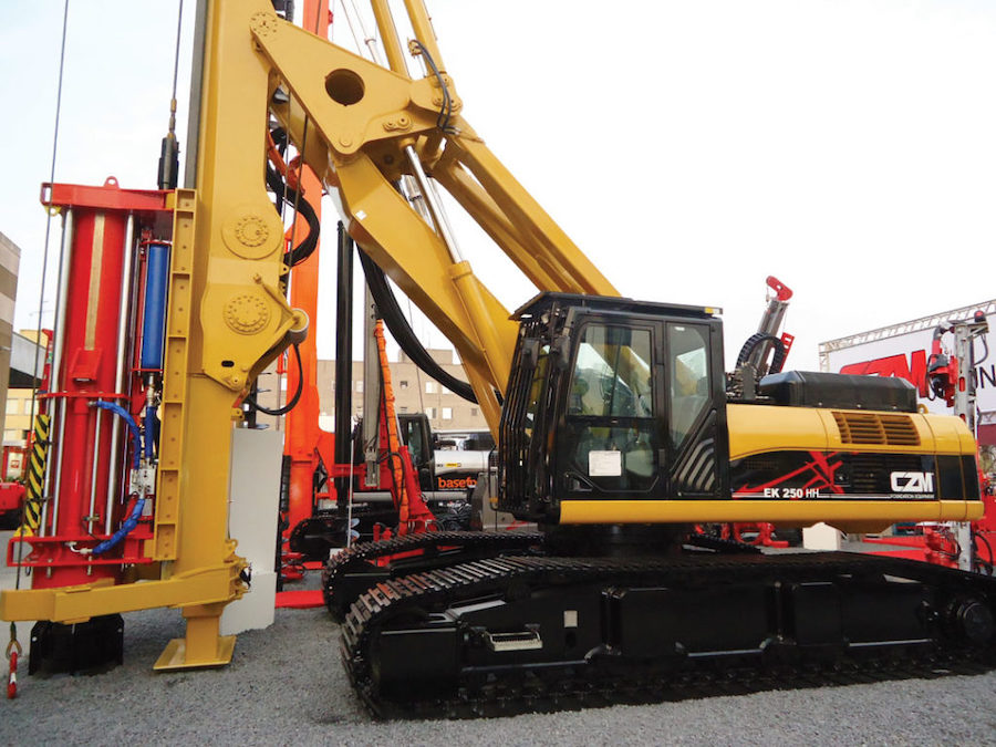
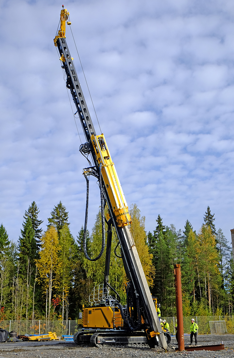
In addition to advances with the piles themselves, the rigs that drove them also evolved. Skid rigs were most commonly used before the development of crane-mounted rigs. Once mobile crane rigs came into existence, the use of skid rigs stopped.
Pile Dynamics
While pile-driving may seem like a simple process — driving a pile into the ground using force — successful pile-driving actually requires knowledge of multiple types of engineering. This includes an understanding of how the pile will interact with the soils (geotechnical engineering), the dynamics of moving bodies (engineer mechanics) and the stresses during driving and after installation (structural engineering). This is best demonstrated through an examination of pile dynamics.
The dynamic formula was the first attempt to create an equation that would model the dynamics of pile driving and make it useful for contractors. The dynamic formula used Newtonian impact mechanics as a way of modeling the motion of the pile. The resulting formula could then be applied to the work at hand. The most popular dynamic formula is the Engineering News formula.
While the dynamic formula was used extensively in the past, when construction projects began to use concrete and steel pipes, it lost its utility. The dynamic formula fails to take into account the driving system and the soil as it interacts with the pile. In addition, it models the pile as one rigid mass. As a result, use of the dynamic formula with concrete piles led to tension cracking.
The wave equation — or stress-wave theory — addressed many of these issues. Australian David Victor Isaacs studied the use of the dynamic formula with concrete piles, and developed a mathematical model that took into account the successive transmission and reflection of waves. In doing so, he could account for the stresses and displacements of the pile as it was driven. This formula also considers factors such as tension stresses in concrete piles, the effect of ram weight, and the impact of hammer cushion stiffness and drive cap weight.
The British Building Research Board added to Isaacs’ work by commissioning a study on stress wavs in piles. The study led to the development of a series of charts, which could then be used to estimate pile stresses and resistance for concrete piles. The study also addressed a number of technical issues that are still of interest to this day, such as instrumentation and data collection on stresses and forces in piles, the effect of the hammer cushion on the generation and effect of the pile stress wave, the relationship of ram weight to pile weight and cross section, and drop tower testing on cushion material to determine cushion stiffness.
After World War II, mechanical engineer E.A.L. Smith of the Raymond Concrete Pile Company developed a numerical method to model stress waves in piles and pile behavior. Smith’s technique consisted of five primary elements:
- Dividing the pile into a series of springs and masses;
- Integrating the model using a first order finite difference technique;
- Modeling the hammer and pile cushions using a static hysteresis technique;
- Modeling the soil as a combination of velocity-dependent dampers and displacement-dependent dampers; and
- Modeling the non-linearities of the soil.
The soil model that Smith proposed is still standard in many wave equations in use today, including the Texas Transportation Institute program, which was developed using Smith’s model. In the 1960’s, the WEAP program added another element: the combustion complexities of diesel hammers.
Beyond the dynamic formula, field monitoring techniques can also be used to understand pile dynamics. Geotechnical engineering principles that account for the uncertainty created by the use of soil and rock advanced the formulas used for pile-driving. Initially, the blow count of the hammer per foot was used as a way to determine the capacity of the pile. Later, the stress wave theory was used to compare the pile force and velocity at a given time. Using this method, the static and dynamic soil resistance components could be separated. A computer model, the Case Pile Wave Analysis Program (or CAPWAP) allowed further refinement of the soil response to determine pile capacity.
The Introduction of Diesel Hammers
In the 1920’s, diesel hammers were first developed in Germany. These types of hammers had two distinct advantages over other pile-driving methods. First, they could operate without an external power source. Second, they were typically lighter than other hammers yet had comparable striking energy. Diesel hammers were first introduced in the United States after the Second World War.
The majority of diesel hammers manufactured today are the tubular, air-cooled type. However, rod-type diesel hammers and water-cooled diesel hammers are used in some applications. The ram of rod-type diesel hammers runs on columns that are similar to those in air/steam hammers. However, the combustion chamber is hidden as the air is compressed and the duel is injected. The chamber is then exposed as the ram is thrown upwards from the combustion. Today, rod-type diesel hammers are used only for very small diesel hammers. In contrast, water-cooled diesel hammers have a water tank that surrounds the combustion chamber. While this model allows for superior cooling capability, they are inconvenient to use. As a result, water-cooled diesel hammers are not popular in the construction industry.
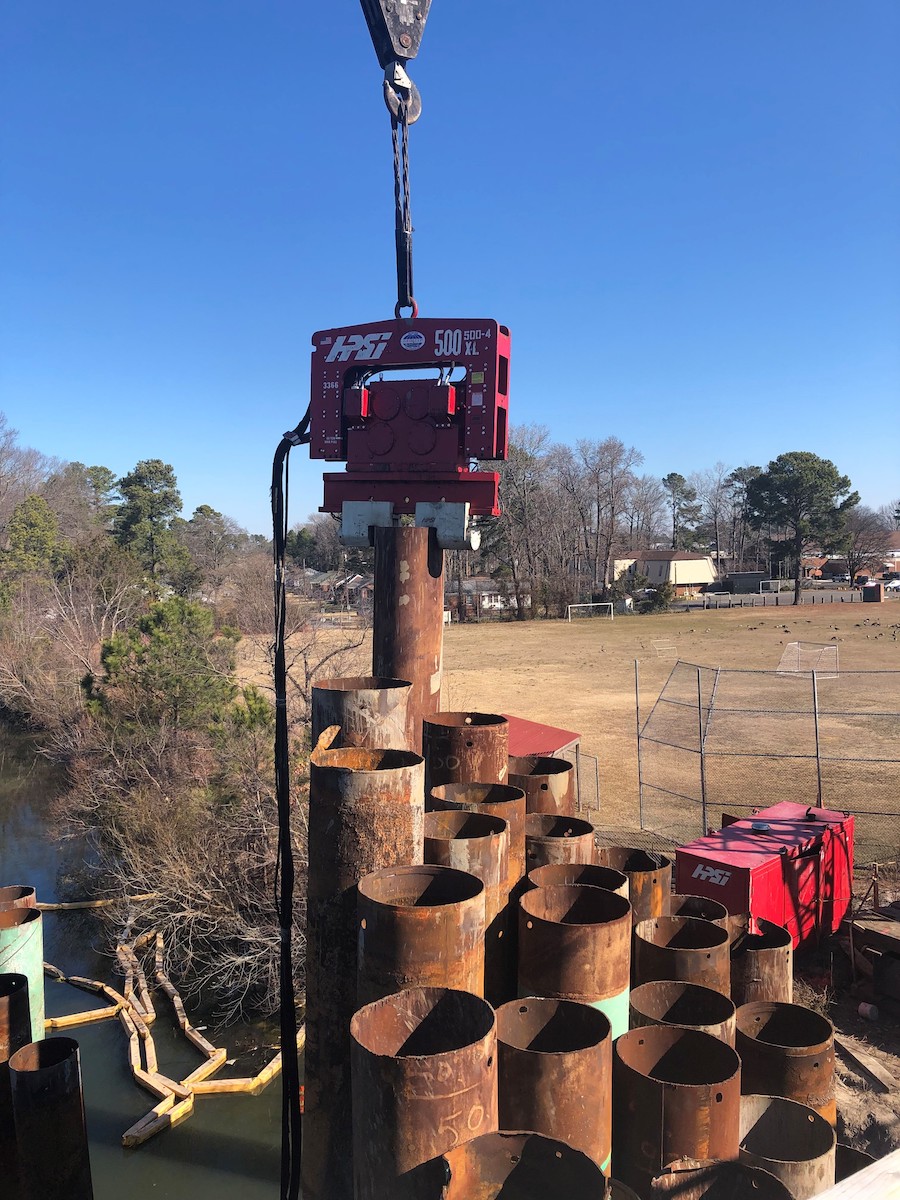
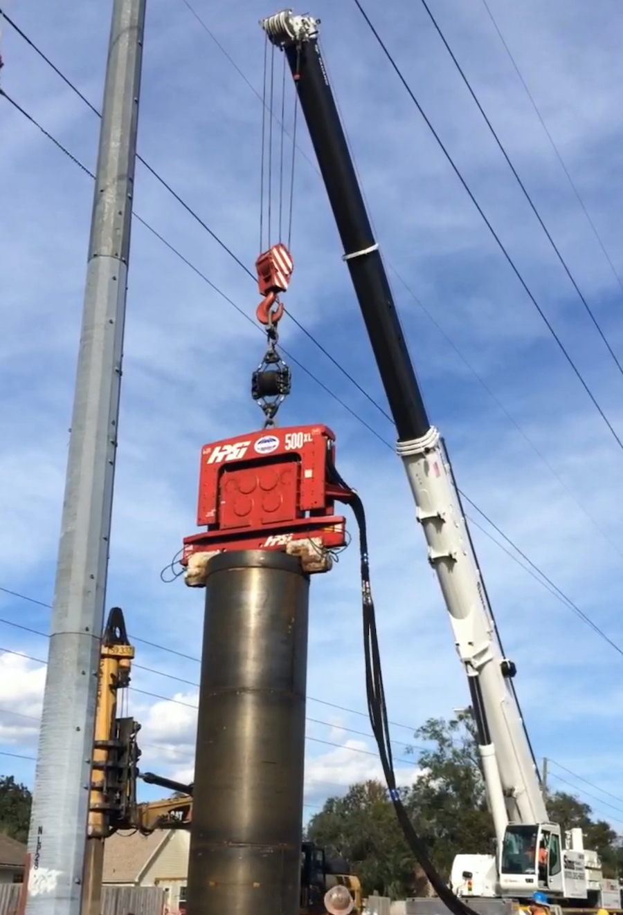
Vibratory Hammers
In the twentieth century, engineers in the former Soviet Union developed the first vibratory pile driver. This hammer was powered by a 28 kilowatt electric motor, and had a dynamic force of 214 kN. Through the 1950’s and after, the Soviets developed a variety of vibratory pile-driving hammers and soil drilling equipment.
Two of the most important types of vibratory hammers designed by the Soviets include the VPM-170 and the VU-1.6. The VPM-170 could drive pile pipes of 1600 millimeters in diameter into any type of soil other than rocky soils. It could also operate in two different frequencies. The VU-1.6 could drive the same size of pipe to depths up to 30 meters. It could also remove the plug from the pile while driving. This hammer had a large center hole, which allowed it to remove soil without stopping the pile driver.
This Soviet technology was licensed to the Japanese, who then developed their own vibratory hammers. Of note is the Uraga hammer, which involved the placement of an electric motor inside of each eccentric. This made the Uraga hammer a “directly driven” machine.
In 1969, the Americans introduced their first hydraulic vibratory hammer, the MKT V-10. This machine differs from modern vibratory hammers in a number of ways. First, it used steel coils springs to provide dampening for the crane boom and hook; modern machines typically use rubber springs. Second, the V-10’s eccentrics were long and were mounted perpendicular to the machine itself. Today, most machines mount the eccentrics from the front to the back of the case and drive them directly or through a speed-changing pinion gear. Over time, Americans have developed a unique type of vibratory hammer with slim throat hammers for sheet pile driving, hydraulic drive, and high power engines, pumps and motors.
Impact – Vibration Hammers
The first impact-vibration hammer was built in the Soviet Union in 1949. This type of hammer involves a vibratory pile driver that imparts both vibrations and impacts while driving the pile. The initial impact-vibration hammer was welded to the top of a metallic tube, and the hammer then drove the rube into a variety of soils. The results of driving piles in this way were compared against pile driving using only vibration. The comparison of these two results demonstrated that impact-vibration driving is substantially more efficient in terms of maximum driving depth and pile installation speed.
The impact-vibration hammer was first used in the construction of the Stalingrad (now Volgograd) power plant. Using these hammers, piles were driven into medium-firm sandstone to construction an anti-filtration wall under the dam. The impact-vibration hammers used on this project were able to outperform conventional vibratory, air/steam and diesel hammers. The successful use of these hammers led to more widespread use, particularly in Europe.
Overview of Pile Foundation Design and Construction
Unlike structural design, the design of pile foundation is not neat and precise. The way that the piles and the surrounding soils interact adds a level of complexity to the process, with the introduction of piles into the soil typically altering the character of the soil. As a result, intense strains near the piles often occur. Because soils are not homogenous and pile grouping and shaping can differ widely, pile foundation design and construction can be a challenging process.
Instead of attempting to broadly characterize pile behavior, it makes more sense to work to understand the factors that influence the successful design of pile foundations. The foundation engineer must have an understanding of the following major factors:
- Foundation loads;
- Subsurface conditions;
- The significance of special design events;
- Foundation performance criteria; and
- Current practices in foundation design and construction specific to the area where the work is to be done.
An experienced geotechnical engineer should be consulted from the initial planning stages to final design and construction. This engineer can assist in selecting the pile type, estimating pile length, and choosing the best method to determine pile capacity.
To successfully translate the pile design into construction, the engineers must rate the requirements of the static analysis methods, the dynamic methods of field installation and construction control. The tools that are to be used for the pile foundation should be explicitly incorporated into the plans.
A pile foundation must meet the design requirements for compressive, lateral, and uplift capacity. To achieve this goal, contractors may need to drive piles to a predetermined length or for a required ultimate capacity. Care should be taken to avoid excessive driving, which can lead to pile damage and/or foundation cost overruns. Using wave equation analysis, dynamic monitoring of the pile driving process, and static load testing can all assist in achieving these objectives.
Throughout construction, knowledgable engineers should supervise and inspect the installation of the piles. The best designs, plans and specifications will often fail if there is not adequate supervision and inspection. Finally, a post-construction review of pile driving results as compared to predictions, pile length, field problems and load test capacities is necessary to help the involved engineers gain experience and better plan the next pile-driven foundation.
The process of designing and constructing a pile-driven foundation is unique to other types of structural design and construction. Pile capacity must be accounted for in both design and construction. The best way to do so is to use dynamic data rather than static analysis methods. In addition, pile drivability should be considered during design, as large costs may be generated if the piles that have been selected and planned for cannot be driven.
The design and construction process for driven pile foundations can be outlined through the use of an 18 block flow chart, as follows:
- Establish requirements for structural conditions and site characterization: determine the general structure requirements.
- Obtain general site geology: this may involve extensive geologic studies or a superficial investigation.
- Collect foundation experience from the area: consult with contractors who have completed pile-driven foundations in the area.
- Develop and execute subsurface exploration program: make decisions about what information must be obtained at the site.
- Evaluate information and select foundation system: use the information gathered above to make a determination about the proper foundation system.
- Deep foundation: decide between driven piles and a deep foundation system
- Driven pile
- Select driven pile type based on the use of formulas and in consideration of the structural capacity of a pile, the geotechnical capacities of the pile type for the soil conditions at the site, the capability of available contractors, and cost.
- Calculate pile length, capacity and performance
- Calculate drivability: this is done by using the wave equation program.
- Design satisfactory: review all aspects of the design and make changes as necessary
- Prepare plans and specifications, set field capacity determination procedure
- Contractor selection
- Perform wave equation analysis of contractor’s equipment submission: the analysis should be re-done based on the pile driving equipment that the contractor plans to use.
- Set preliminary driving criteria
- Drive test pile and evaluate capacity
- Adjust driving criteria or design
- Construction control: supervise and review pile driving as it occurs.
Throughout the process, good communication is necessary to successfully complete any pile-driving project. This includes interaction between engineers during the design state, consulting with experts, and talking directly to drill crews and laboratory personnel. During construction, all parties should continue to communicate so that they can resolve any construction issues as they occur.
Pile-driving is an important construction technique that is used throughout the world. Developed at the dawn of civilization when humans began to build structures, its utility has been proven time and again. Learning about the history — and future — of driven pile construction can help to inform your choices as you undertake a construction project.
View the complete article here.
What are the advantages of using concrete piles over timber piles in pile driving?
Concrete piles offer greater durability, allowing for deeper driving capacities (60 kips or greater) compared to timber piles, resulting in fewer piles and smaller footings for the same load.
How has pile driving technology evolved over time, specifically regarding vibratory hammers?
Pile driving technology has evolved with the introduction of vibratory hammers, initially developed by the Soviet Union, leading to innovations like the hydraulic vibratory hammer and impact-vibration hammer, contributing to more efficient and versatile pile installation methods.