


The Different Types of Deep Foundations

The ultimate viability of any construction project depends in large part on the structural integrity of its foundation. Without an adequate foundation, a structure will lack strength, and may fail over the long-term. That is why it is absolutely vital that any contractor or project manager administering a project for structure construction become intimately familiar with the requirements for a deep foundation that can sustain the design loadings throughout its projected life. In this two-part article, we will explore the steps involved in determining what type of foundation is suitable for a given project, administering a foundation contract, and various types of foundations that can be utilized based on the type of structure involved.
The Foundation Investigation
At the inception of any structure construction project, a contractor or project manager should consult with an engineer to perform a foundation investigation, draft a foundation report and develop of log of test borings. The foundation investigation is a necessary step to ensure that the proper foundation is chosen based on the soil conditions, type of structure, and other factors.
The engineer will start a foundation investigation by collecting as much information as possible about the proposed construction site. This will include any previously drafted foundation reports, preliminary structure plans, as-built plans, the area’s historical seismicity information, and historical subsurface conditions. This information will be used during the planning phase to assist the engineer during fieldwork.
In order to effectively determine the depth of rock, rock type and quality, soil types and strengths and groundwater levels, a subsurface drilling operation must be conducted as part of the foundation investigation. Prior to embarking on the drilling operation, the engineer will draft a drilling plan to make efficient use of the drilling equipment and personnel, outlining locations for drilling in accordance with the structure’s proposed foundation. The engineer will direct the subsurface drilling operation, and will perform testing at the site, developing a log of test borings to be included as part of the overall foundation investigation.
The drilling operation will help to determine a soil and/or rock profile, allowing the engineer to develop a visual representation of the subsurface conditions, as interpreted during investigations and laboratory testing. Observations made during testing — such as the difficulties or changes in the rate of the drilling tool advancement or the appearance and feel of the cuttings — can be noted in field logs, and used to estimate the properties of the soil or rock below the surface. Similarly, any groundwater encountered is noted, and used to develop the soil and rock profile. Soil samples are taken, in both disturbed and undisturbed form, to be used to various tests, such as identification and classification tests (disturbed samples) and consolidation and strength tests (undisturbed samples).
Once the subsurface investigation and laboratory testing has been completed, the log of test borings is developed. This log includes a plot that shows the location of each boring that was taken during the drilling operation, providing a graphic description of the various layers of geological formations, soils and the location of the groundwater table, if encountered. The properties of the rock and soil of the project site are also described.
The final foundation report contains all of the information that was gathered during the foundation investigation, providing the contractor with an evaluation of the geological formation and soils at the proposed project site. The report should also describe and evaluate any seismic hazards that may be present, where applicable. It should recommend the type of foundation that should be used to support the proposed structure, along with recommendations for bottom of footing elevations, pile type, and size and tip elevations. In areas where seismic activity is a concern, recommendations for seismic design criteria should also be included. A thorough foundation report typically also includes information about anticipated problems that may arise during construction, such as soil compaction, caving, variations in pile driving, and issues due to ground water. Any problems that may impact construction that are included in the foundation report should be discussed with the contractor as soon as possible.
Selecting the Proper Foundation Type
The foundation of a structure must transmit service and loads from the structure itself into the supporting geological medium. Choosing a foundation that is appropriate for a given structure is determined by a number of different factors, including load requirements, site-specific geologic conditions, overhead clearance, vertical clearances, site accessibility, existing utilities, proximity of existing facilities to buildings and railroads, and noise restrictions. Using the foundation report, a contractor can work with a designer to select the appropriate foundation type based on the recommendations in the report.
There are numerous different types of structure foundations, which fall into four primary categories: (1) footing foundations, which may also be referred to as spread footings; (2) driven pile-supported foundations; (3) non-driven pile supported foundations; and (4) special case foundation types. Special case foundation types can include a number of different types of foundations, such as soil nails, ground anchors, pier columns, micropiles, and alternative piles.
Footing foundations are more cost-effective than pile-supported foundations, and their use is virtually unlimited. Considerations in selecting footing foundations include the location of the water table, the potential for scour or undermining and the soil profile. In addition, the size and shape of the footing, adjacent structures and existing utilities should be considered.
Non-driven pile foundations include cast-in-drilled hole (CIDH) concrete piles and alternative footing design piles. CIDH piles are generally used when piles are required and foundation conditions permit their use, as they tend to be more economical. Alternative footing design piles are used whenever conditions warrant their use, and are done on an experimental basis.
Contractors should analyze the location of the water table, potential for caving and soil profile, along with adjacent structures, existing utilizing, restricted overhead clearances and accessibility.
Special case foundations have relatively limited use. They include micropiles, which are small diameter piles of less than twelve inches that are drilled and filled with reinforcement and grout, and alternative piles, such as auger-cast piles, that are used for soil improvement and where environmental considerations preclude the use of other foundations.
Administering the Contract
Once the foundation investigation has been completed and the foundation type selected, one of the next step in the process is ensuring the work contemplated in the contract is completed in accordance with it terms. This includes making sure that the foundation is properly constructed so that the structural integrity of the foundation and the structure itself are intact. Administration of the contract requires the engineer and the contractor to work together so that any changes that may arise during the construction process can be resolve in a manner that does not negatively affect the foundation.
Both before and during construction, the engineer should meet or otherwise communicate regularly with the contractor or designer to discuss substructure considerations and foundation details. These meetings can be used to talk about the potential risks or challenges involved in constructing the foundation.
Before construction begins, all utility locations that are shown on the contract plans should be verified with local utility companies. The engineer should request as-built plans from local municipalities and conduct field meetings to verify the locations of these facilities before excavation begins. The contractor is responsible for notifying utility companies of construction before excavation, so that any utilities that need to be relocated can be moved.
Depending on the type of foundation chosen, there are various parameters that must be met. For example, for driven pile foundations, the piles must achieve a specified nominal driving resistance and penetrate to the specified tip elevation unless a contract specifies otherwise. Similarly, cast-in-drilled-hole piles must penetrate to at least the specified tip elevation shown on the contract plans.
Types of Foundations
There are a variety of foundations that can be utilized on various structural construction projects. A foundation should be carefully chosen based on the analysis performed by an engineer through a foundation investigation. In addition, other factors, such as the cost of each selection and the location of utilities, should be reviewed before coming to a final determination.
Footing Foundations
Footing foundations are the most economical type of foundation. Also known as spread, combined or mat footings, this type of foundation transmits design loads into the underlying soil mass through direct contact with the soil immediately beneath the footing. This is in contrast to pile-supported foundations, which rely on pile friction and/or end bearing to transmit design loads into the adjacent soil mass.
When constructing footing foundations, care must be taken so that they are sized appropriately so the maximum soil-bearing pressure does not exceed the allowable soil bearing capacity of the underlying soil mass. Because the load-bearing capacity of most soils is relatively low, at two to five tons per square foot, footing areas can be large in relation to the cross section of the supported member, such as a bridge column.
The potential for settlement of the footing should also be considered when choosing this type of foundation. Settlement must not exceed tolerable limits established for differential and total settlement. Each footing must be structurally capable of spreading design loads laterally across the entire footing area.
Because the soil mass is supporting the entire foundation, the quality of the soil is of the utmost importance when using footing foundations. For this reason, it is vital to have a well-drafted foundation report prior to choosing a footing foundation. The bearing capacity of a soil mass that supports a footing foundation is the maximum pressure that can be applied to the soil without causing shear failure or excessive settlement.
Shear failure can occur in one of three ways — general shear, punching shear, or local shear. General shear occurs when a soil wedge immediately beneath the footing pushes the zone of soil next to it laterally. This horizontal displacement of soil causes the zone of soil adjunct to it to move upward. General shear failure is considered to be a brittle failure. It is typically sudden and catastrophic. Although bulging on the ground surface may be observed on both sides of the footing after failure, it usually occurs on one side of the footing. A punching shear failure occurs when soil is compressed immediately beneath the footing, which is accompanied by vertical movement of the footing. There is no rotation of the footing, and little ground surface evidence of the failure. Local shear failure can exhibit characteristics of both general and punching shear failures, including soil compression beneath the footing and potential ground surface bulging.
There are two general types of footing foundations: spread footings that support a single structural member, and combined footings that support two or more structural members. As a general rule, columns are located at the center of spread footings, while retaining wall are typically located in eccentric locations in relation to the centerline of a continuous footing. Locating a load away from the center of the footing can create an eccentricity that changes the distribution of loads in the soil, which may then create a bearing pressure that exceeds the allowable bearing capacity. This can increase the further the column is placed from the center, or as the eccentricity increases. Problems that result from eccentricities can be resolved by combining two or more columns into a single footing. This is typically done by either using a single rectangular or trapezeoidal footing to support two columns, or by connecting two spread footings with a narrow concrete beam.
Footing foundations will settle over time. This is due to the soil becoming more dense from the additional weight of the structure. Soils with relatively low densities will see more settlement than well-compacted soils with higher densities.
In some situations, contractors will need to build a foundation at a location where the soil is not suitable for the intended purpose. This is often the case in the construction of bridges and other structures along water lines. In these situations, ground improvement or soil modification can be used to avoid the cost of a pile foundation. These techniques can increase the bearing capacity of the soil, typically through densification by the addition of cement or the addition of grouts to compress and bind the soils. Some modification techniques may also include a settlement period, where the foundation is preloaded with a surcharge prior to foundation construction to allow for settlement. This typically occurs for sixty days, with extensions as needed to allow for further settlement.
Excavation is a necessary step in constructing footing foundations. Open excavations, or tenches are potentially dangerous, and should be performed in accordance with workplace safety rules. Care must be taken to remove surcharge loads, equipment and/or excavation spoils at a sufficient distance from the edge of excavations to maintain slope stability. For cofferdams or shored excavations, an engineered plan must be approved by a registered engineer. A minimum setback for a surcharge is required when on level ground, usually equal to the depth of the excavation. Wet excavations can present unique challenges. Contractors often use sump pumps to remove surface water or groundwater that enter an excavation site, so that this water will not disturb the foundation’s bearing surface. If sump pumps are insufficient, other methods may be used, such as cofferdams, deep wells, well points, and other forms of construction site dewatering.
Controlling groundwater is an essential component of ensuring that the underlying soil is sufficiently stable to support the new foundation. However, this is not the only factor that must be taken into consideration; soil heave and piping should also be analyzed as they relate to stability of the bottom of the excavation. Heave is when the static or hydraulic pressures of the surrounding material causes the upward movement of the soil in the bottom of the excavation, which corresponds with the settlement of the surrounding material. It often occurs in soft clays. Piping generally occurs in materials that are pervious, and can occur when an unbalanced hydrostatic head exists. This can cause large upward flows of water into the excavation, transporting materials in the process, which may result in settlement of the surrounding area.
As with any construction, problems may arise during excavation of a footing. After an excavation has been completed, the surface should be inspected thoroughly by an engineer to determine if it is suitable, disturbed, contaminated or unsuitable. Disturbed and/or contaminated material must be removed to expose a suitable foundation surface. If there is unsuitable foundation material, hand excavating a small explorer hole to determine the limits of the unstable material may be appropriate to determine a plan to move forward with the foundation. Of course, these changes may result in a different elevation than what is required in the construction plans. Corrective action may include replacement of the original foundation material to achieve the original bottom-of-footing-elevation, or revisions to the structure to address a different bottom-of-footing elevation.
Pile Foundations
When underlying soils are not capable of resisting the loads from a structure, pile foundations can be utilized. In this type of foundation, piling is placed in the ground through the poor quality soil or other material so that the load is borne by more competent soils. These piles are either driven into the ground, or holes are filled and then filled with reinforced concrete. The piles transfer the load of the foundation and structure by either bearing on the competent material or through the friction between the soil and the pile.
There are two primary types of pile foundations: displacement piles and replacement piles. A displacement pile includes any type of pile that is driven or vibrated into the ground, thus displacing the surrounding soil. In contrast, a replacement pile is one that is placed or constructed into a previously drilled borehole, replacing the excavated soil.
Driven piles are braced structural columns that are driven, pushed or otherwise forced into the soil. When structures need to be supported on poor quality soil, two types of pile foundations are typically used: piles and piers. Piles are more commonly used, and are generally small diameter piers working in groups. Pier foundations are large in diameter, and work independently. They have gained favor in recent years as they perform better in seismic events. Piles and piers can be classified as friction piles, end bearing piles, or a combination of the two. Both types of piles can provide lateral stability and foundation, while friction piles can transfer both tensile and compressive forces to the surrounding soil.
There are three main types of driven piles, including concrete, steel and timber. Concrete driven piles can be made in a variety of sizes and shapes and can be constructed in a variety of ways. They are generally less expensive than steel driven piles, but require larger equipment to handle them. Steel driven piles are generally used for lower capacity pipes, and is more expire on a “per foot” basis than other types of piles. However, it has a number of advantages, such as resistance to corrosion, the ability to penetrate to bedrock, relatively light weight, and ability to be driven without displacing a substantial amount of material. Timber piles can be used for temporary construction, revetments, fenders and similar work, as well as in permanent construction. They are difficult to extend, hard to anchor and can easily be damages. They also cannot bear a substantial load compared to other types of piles.
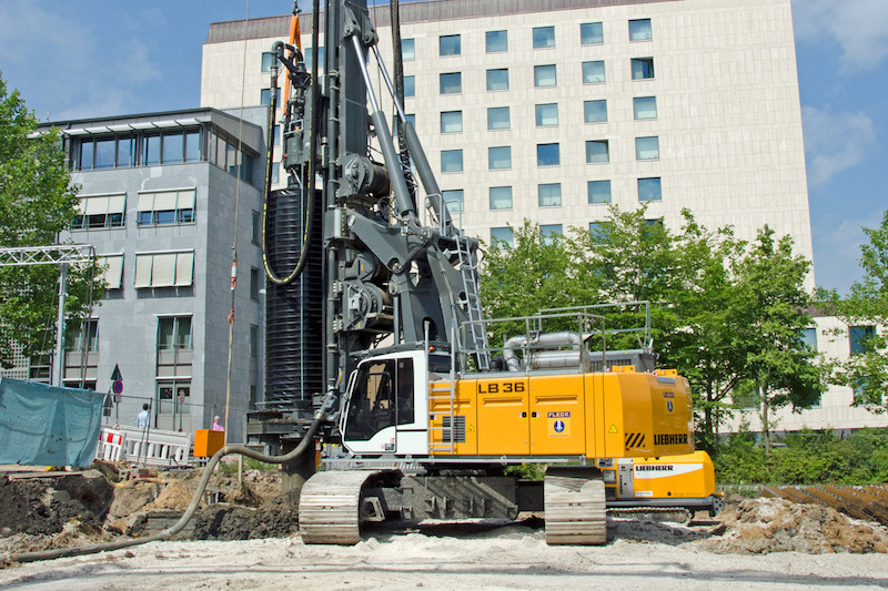
Cast-in-Drilled Hole Piles
Cast-in-Drilled-Hole (CIDH) piles are made of reinforced concrete that is cast into holes drilled into the ground to a specified drill elevation. The diameter for these holes can range from twelve to 168 inches, with lengths from 10 feet to over 200 feet. CIDH piles are often favored over other types of piling because they are more cost-effective, and in areas where vibrations from pile driving operations might damage adjacent infrastructure. These types of piles are often used in the construction of bridges.
Despite the advantages of CIDH piles, their use is limited to two ground conditions: placed dry conditions, typically without inspection pipes, or placed under slurry or with the use of temporary casing to control groundwater, always with inspection pipes. A dry hole is a drilled hole that does not require any interventions to keep it free from water, with no standing or accumulating water at the bottom of the drilled hole. A dewatered hole is a drilled hole is one where water may be present, but it accumulates at a rate of less than twelve inches per hour and can be controlled by pumps or other methods. The dry method for CIDH piles can be used for dry or dewatered holes. A wet hole is a drilled hole where water accumulates at a rate of more than twelve inches per hour, or where a temporary casing is used to reduce the rate of water accumulation is used to reduce the rate of water accumulation. Inspection pipes and the wet method of construction are always required for wet holes.
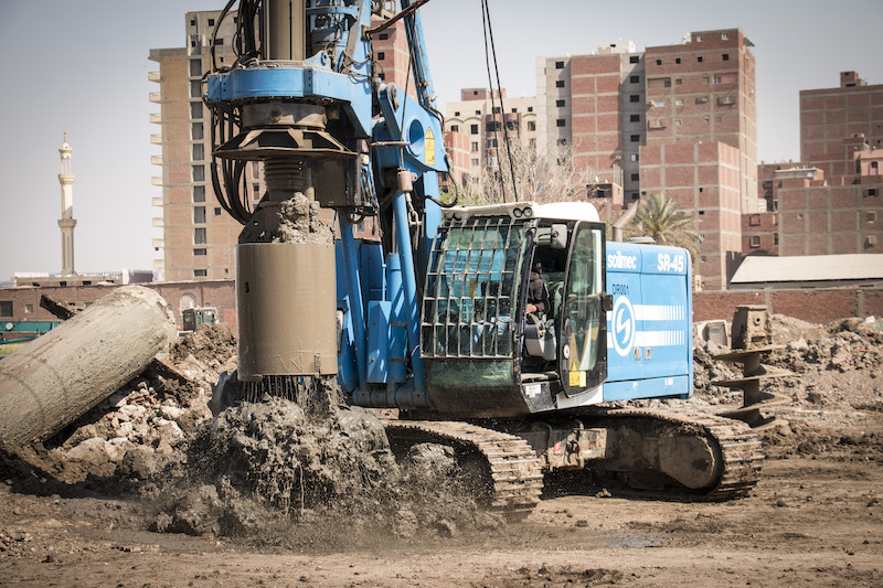
A drilling auger is most often used to drill holes for CIDH piles. Both continuous flight augers and short section augers may be used to construct these holes in a variety of soil and rock types and conditions. Continuous flight augers have flight lengths that are longer than the hole that is being drilled. Drilling is performed in one continuous operation, with the drilling action forcing the cuttings up and out of the hole. The material then has to be shoveled away from the hole. This type of auger is most often used for short piles or for pre-drilling driven piles. Short flight augers are usually between five and eight feet in length. As the operation progresses, the material is spun off the flights onto a spoil pile and the process is repeated. They are typically used for smaller diameter piles. Augers may be single or double flight depending on the needs of a particular project. Rock augers, equipped with high-strength steel cutting teeth that can cut through soft rock, are the preferred tool for drilling in materials that have a high concentration of cobbles or boulders.
Other tools can be used to ensure that holes are properly drilled for CIDH piles. This includes core barrels, which are used to drill through hard rock formations, large boulders or concrete. Down-hole hammers can also be used to drill through hard rock formations by using compressed air or hydraulic-powered percussion drilling heads to pulverize the formation and blow the debris from the hole. Rotators and oscillators can be used to advance a drilled hole through difficult ground formations by using a hydraulic-powered apparatus to rotate and push down on a drilling casing. The drilling casing preserves the integrity of the drilled hole, even when the ground is wet or otherwise unstable. The casing will remain in the hole until the pile concrete is placed. Reverse circulation drilling equipment is used to advance a drilled hole in situations where the ground is wet and drilling is difficult. Using this tool, very deep holes can be advanced without cycling in and out of the hole to remove cuttings. Temporary steel casino can also be used to support drilled holes when the ground conditions are unstable; they are advanced into the ground using various methods, and then extracted from the hole once the concrete is poured. As a general rule, regardless of the type of equipment used, drilling is performed with portable drilling rigs. These units can be crane-mounted, truck-mounted, or self-propelled crawler-mounted.
A number of different problems may arise during drilling of CIDH piles. This can include cave-ins, groundwater and issues with utilities. Taking corrective action is often necessary to advance the foundation construction. For cave-ins, a temporary casing can be placed, a drilling slurry may be used, or a low cement/sand mix can be used and the area of the cave-in can be re-drilled. In the event that groundwater appears during drilling. The same low cement/sand mix can be used and the hole can be re-drilled. Otherwise, a pump can be used to removed water once the hole has been drilled to tip elevation. A drilling slurry may be used, or the entire area can be de-watered using a variety of methods. Alternatively, an alternative type of piling could be substituted. If drilling near utilities, an issue may arise where there is a buried manmade object or the project changes such that drilling may need to take place near utilities. If that occurs, the contractor should consult with local utility companies to resolve the issue.
Failures during drilling may also cause problems with the resulting CIDH piles. For example, if a cleanout bucket is not used to clean up the bottom of the drilled hole, the pile may bear on soft material, compromising the value of the pile. If the bottom of the hole is not flattened, the concrete may crush at the tip of the pile, reducing its capacity and potentially causing differential settlement. If drill cuttings are smeared on the sides of the drilled hole, the pile’s capacity to transfer loads through skin friction may be degraded. Each of these problems are preventable by adhering to best practicing and inspecting the drilled holes throughout the process.
Similarly, the placement of the concrete can cause problems with the piles. This includes a cave-in at the top of the concrete or sloughing material that occurs during concrete placement, which can result in degraded concrete, reducing the capacity of the pile. If a contractor tailgates concrete into the drilled hole without the use of a hopper to guide it, the concrete may fall into the pile bar cage and segregate, which can lead to defective concrete. If groundwater is not removed from the drilled hold, this can also cause defective concrete at the bottom of the pile; if the pile were designed for end bearing, its capacity would be reduced. Finally, if a new hole is drilled adjacent to a freshly poured pile or concrete or placed in a drilled hole that is too close to an adjacent open drilled hole, a sidewall blowout of the freshly poured pile can occur, leading the pile bar reinforcement cage to buckle. As with drilling problems, most of these issues are preventable and can be avoided through inspection and adherence to contract specifications. However, if a cave-in happens during concrete placement, the contractor may need to remove the pile bar reinforcement cage and concrete and start the process over again.
Casing removal can also lead to pile defects. This typically happens when a contractor waits too long to pull the casing during concrete placing. Doing so can result in one of three problems: (1) the concrete may set up and come up with the casing; (2) the concrete may set up and the casing cannot be removed; or (3) the concrete sets up enough so that it cannot fill the voids left when the casing is removed. Problems with casings have historically caused the worst types of CIDH pile defects, such as voids in the pile at the bottom of the casing leading to a cave-in, or loss of capacity to transfer skin friction to the ground. Concrete with higher fluidity should generally be used for CIDH piles, as it will consolidate and fill in the voids better than concrete with lower fluidity.
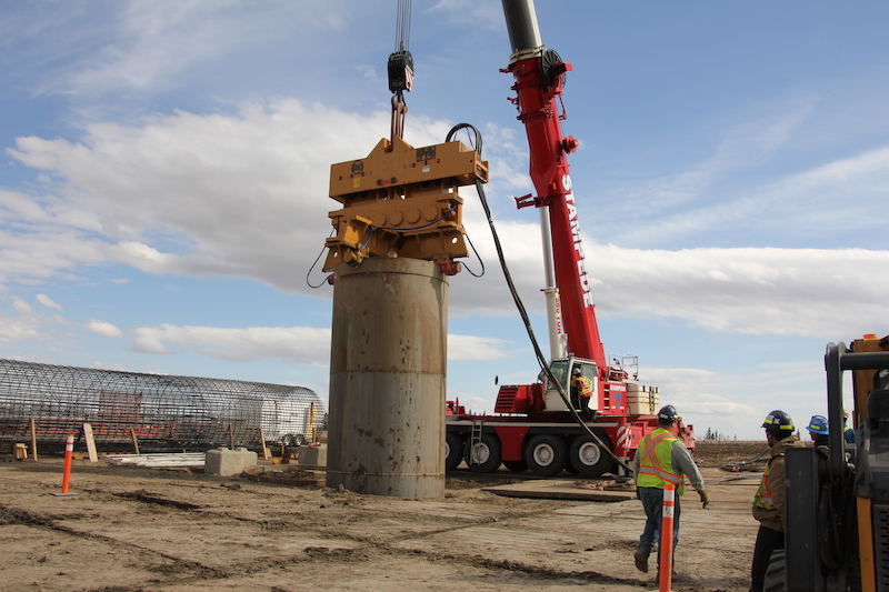
Driven Piles
Driving piles for structure foundations is one of the oldest practices in construction, dating back centuries. While timber was first used in this practice, over time, piles evolved to include concrete, and the present steel H-piles and pipe piles. Pile driving involves forcing a pile into the ground, displacing the soil mass across the cross section of the pile in the process. The most common method of accomplishing this goal is through the use of an impact type hammer.
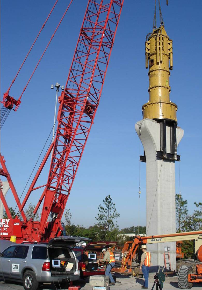
There are a variety of hammers used to drive piles, with the specific type utilized based on site specific construction challenges, such as limited space, noise levels, or unusual tip or breaking requirements. A pile hammer is not only used as a drilling tool, but it can also serve as a measuring device for the engineer to determine the bearing capacity of the pile. The amount of energy and the penetration per blow can be used by an engineer to calculate bearing capacity.
Economics are often the leading consideration when selecting a hammer size and type. Large hammers provide a high amount of energy that can quickly advance a pile and reduce driving time. However, heavy hammers require heavy loads and cranes, leading to decreased mobility and higher equipment costs. Large hammers also deliver more energy to the pile, which can result in pile damage and pile stress.
A drop hammer is one of the oldest types of hammers used to drive piles. The concept is relatively simple: a weight is lifted a specified distance by a rope or cable, and then allowed to drop and strike a pile cap block. A variation of the drop hammer that requires a minimal amount of headroom is being used on job sites as well. This type of hammer uses a closed-ended pipe pile that is wide enough to allow the drop hammer to run inside of its walls, with the impact occurring near the tip of the pile. This type of drop hammer actually pulls the pile down rather than pushing it from above. As a general rule, drop hammers are only used when specially permitted.
A single action steam or air hammer is the simplest powered hammer. It consists of a heavy ram that is connected to a piston that is then enclosed in a chamber. Steam or air lifts the ram to a certain height, and the ram then falls by its own weight. A double acting steam or air hammer operates in the same manner, but instead of just using air or steam to lift the piston, it also uses air or steam to accelerate it downward faster than it otherwise would move by gravity alone. This additional energy increases the effectiveness of the hammer, reducing stroke lengths, and making it ideal for low overhead clearance projects. Some of these hammers are also enclosed, and can be operated while submerged in water.
The external combustion hammer, also known as the differential acting steam/air hammer, is similar to a double acting hammer. Compressed air or steam is introduced between large and small piston heads to lift the ram to the top of its stroke; the valves are then switched so that the ram accelerates in its down stroke. If hydraulic fluid is used as a fluid in this type of hammer, it is known as a double/differential acting hydraulic hammer.
Diesel pile hammers are fed from fuel tanks that are mounted directly on the hammer, along with pumps. Because they do not require an external energy source and are simple to operate, diesel hammers are commonly used on bridge constructions. Diesel hammers consist of a cylinder-encased ram, an anvil block, a lubrication system, and a fuel injection system that regulates the amount of fuel to each cycle. A cable from the crane lifts the ram, and at the top of the stroke, the ram is allowed to drop. The ram will then activate the cam on the fuel injector, injecting a set amount of fuel into the head of the impact block. Air is trapped in the cylinder as the falling ram passes the exhaust ports, beginning compression. This compression then pushes the anvil and helmet below it against the pile head prior to the blow. The ram then drives the pile into the ground, while simultaneously atomizing the fuel. As the fuel combusts, it pushes the moving pile forward while recoiling the ram. This motion exhausts the gases and equalizes the pressure in the cylinder. The cycle then repeats itself. Diesel hammers are incredible versatile tools, as they can be connected to almost any set of leads, and do not require an outside energy source. Their strokes are longer in harder soils, and slower and shorter in softer soils. However, they are considered to be environmentally unfriendly because they emit exhaust and may leak oil and grease.
Double acting diesel hammers act in a similar fashion to diesel hammers, with the main difference being that the top of the cylinder is capped so that the pressures can be developed on the downward stroke. The compressed air inside of the chamber creates a “bounce chamber,” which halts the upward flight of the ram and allows the downstroke energy to become a product of both gravity and internal pressure.
Vibratory drivers or extractors use two balanced rotating weight sets that are eccentric from their centers of rotation. These weight sets move in opposite directions to set off a vertical vibration that is transmitted to the pile through the hydraulic clamps of the driving head. Vibratory drivers are best used in granular soil, but new techniques have made them more useful in more cohesive soils. They can handle a number of different types of piling, including timber, concrete, steel sheets, steel pile, wide flange sections “H” piles” and cassions. Unlike impact pile hammers, they do not create large amplitude ground vibration, making them a better choice for projects where such vibration could damage adjacent structures.
Hydraulic hammers utilizes an external energy source to lift a hammer to the top of its stroke; the hammer then free falls into the pile, similar to how a drop hammer or diesel hammer works. This type of hammer has a variable stroke, which can be controlled from a detached control box to optimized in order to match the dynamic spring constant of the hammer and pile. This makes hydraulic hammers more efficient than other types of hammers, as energy can be transmitted through the pile to the tip with fewer losses at a lower internal stresses.
There are many challenges that may arise during driving piles, including (1) hard driving; (2) easy driving; and (3) pile alignment. Generally, these issues are caused by soil that is either too hard or too soft, a hammer that is inappropriate for the soil at the construction site, or a pile that is not proper for the soil.
Another problem that may occur is soft piles and re-drive. A pile is considered “soft” if it has been driven to the specified tip elevation but has not obtained the minimum driving nominal resistance. If this occurs, a contractor can continue driving until the minimal nominal penetration can be achieved, install pile lugs on H-piles, or re-drive the piles after initial driving, with the expectation that the piles have set up over time. With the first two options, on-site welding is generally required, which will require quality control measures. Further, the piles may not be able to be spliced in this manner due to load bearing requirements. Re-driving the piles is effective in cohesive soils, but less so in submerged and saturated sands and gravels. In addition, piles can only be driven a certain distance (typically several inches) before set-up is lost.
An engineer must also verify that each pile is in the correct location, and that each is plumb or at the required batter. This should be verified during the initial drilling and driving, as well as throughout the process. If the pile begins to move out of line, alignment corrections should be made.
Having a proper foundation is vital to the success of any structural construction project. In the second of our two-part series, we will explore the necessity of static pile load testing and dynamic monitoring, as well as other types of foundations that may be appropriate for your construction job.
What is the standard process of selecting proper foundation systems for any structure?
It is important for any project to have the correct foundation system for success. The main factors that play in the selection of foundation systems are structure loads, geological conditions, access to the site, overhead/vertical clearance, availability of materials, noise restrictions, environmental restrictions, and cost. It is good to include and specify these parameters at the start of the bidding process for a successful project.
Why is the foundation investigation important in overall project cost and schedule?
Before starting foundation construction, foundation investigation plays an important role in defining correct geology, foundation systems, and efficient drilling operations. The detailed foundation investigation report should include previously drafted foundation reports, preliminary structure plans, as-built plans, the area’s historical seismicity information, historical subsurface conditions, initial boring log information, government survey data, and option of correct foundation systems.