


Ground Freezing at Norris Cut Tunnel
Numerous pipe segments damaged from years of wear and tear were discovered during inspections of an outdated, 1977 wastewater pipeline just south of the Port of Miami. The pipeline’s system included a 54-inch diameter tunnel and force main which ran from Virginia Key Central Wastewater Treatment Plant (CDWWTP), underneath Biscayne Bay Norris Cut, to Fisher Island. The Miami-Dade Water and Sewage Department (MDWASD) decided to replace the system with a new, larger 60- inch diameter tunnel and force main.
PROJECT BACKGROUND
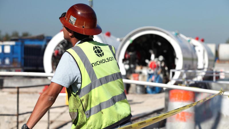
The Norris Cut project is part of a larger, multi-billion dollar initiative to upgrade the region’s aging wastewater and sewage systems. In 2013, Miami-Dade County, the Florida Department of Environmental Protection and local and state governments, agreed to commit resources for the improvement of the county’s pipes, pump stations, and wastewater treatment plants. Completion of the upgrades is anticipated to take close to 10 years. Nicholson Construction Company operated as general contractor for the Norris Cut wastewater upgrade and was responsible for the design, permitting and construction. To assist with the tunneling phase of this project, Nicholson worked closely with tunnel design firm Arup, sister company and worldwide tunneling contractor Bessac and tunnel boring machine (TBM) manufacturer Herrenknecht AG. Nicholson’s contract also included the construction of a launch shaft at CDWWTP and a receiving shaft on Fisher Island.
THE WORK
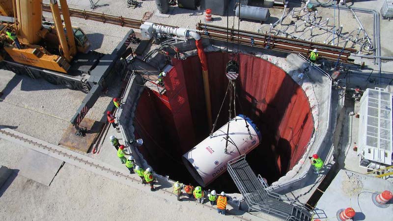
Construction began with the 42-foot diameter secant pile launch shaft on Virginia Key. Once the piles cured and excavation of the middle was performed in the wet. Because of the presence of ground water, Nicholson then utilized the tremie method to install a 6-foot-thick concrete floor. This method includes inserting a waterproof pipe to the base of the shaft, then continuously pumping concrete onto the underwater floor. The concrete displaces the water and is able to achieve full compaction by self-weight. The remaining water was then pumped out to reveal a finished shaft.
Nicholson engineers recognized that the region’s ground conditions would require modification to support the initial launch of the TBM. The geology underneath Biscayne Bay is comprised mainly of Florida’s Fort Thompson Formation, hard limestone with frequent cavities ranging in size from 0.1 to 4 inches, which increases the possibility for cave-in sand/or flooding. To prepare the ground for the TBM launch, Nicholson contracted Soil Freeze, Inc., to freeze the ground at the mouth of the tunnel by inserting pipes into the rock formation and then pumping the pipes with a chilled salt water solution. Over the next 7 to 8 weeks, the ground water within the bedrock froze making it possible for initial excavation and advancement of the TBM.

Several features of the TBM also allowed it to adapt to changing geological conditions with relatively short conversion time. The TBM, given the name “Dorsey” after Miami’s first black millionaire who originally owned Fisher Island, boasts features like slurry mode and dual pressure balance which were designed by Bessac, Arup, and Herrenknect AG.
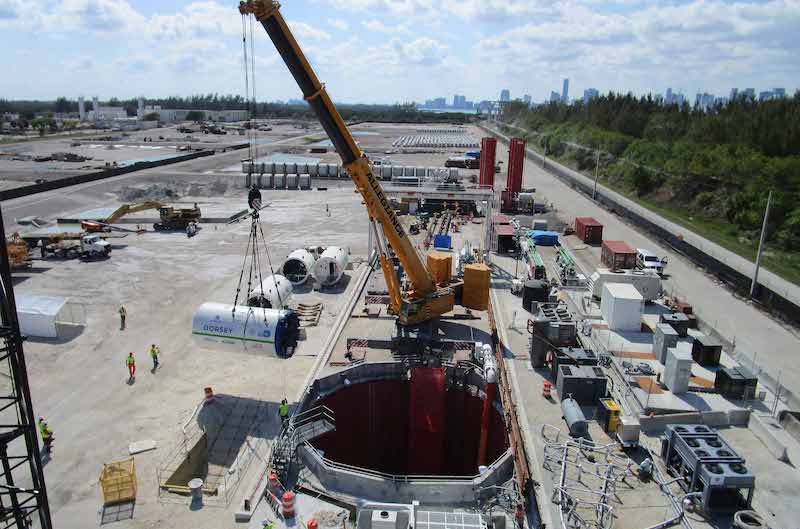
Dorsey was launched from CDWWTP out of the secant pile shaft, and for 24 hours a day, five days a week — with a shift on Saturday — the TBM dug its way towards Fisher Island. After the launch, Nicholson transported its equipment to Fisher Island to construct the soil mixing retrieval shaft. This shaft was built using 7-foot diameter soil mixed columns extending to depths of 87 feet and the middle was excavated in the dry.
After 227 days and tunneling 5,280 feet, Dorsey reached its destination and pulled into in the 28- foot diameter soil mixing retrieval shaft.
The new, updated wastewater pipeline system is fully functional and has an 80 year design life. The successful execution of the Norris Cut Tunnel project is due largely to the collaborative relationship between the Miami-Dade Water and Sewage Department, Nicholson and the other contractors and subcontractors. Under Nicholson’s leadership, this design-build project is part of Florida’s push to further develop the state’s tunneling industry.
Artificial ground freezing is a cost-effective technique used in the construction of drilled shafts and other applications to provide temporary earth support and groundwater control for soil stabilization.
GROUND FREEZING
Localized ground freezing was used to control groundwater inflow during TBM break-out. A block of ground approximately 30 cubic feet was frozen at the TBM break-in as shown in the figure above.
By freezing the water, limestone, sand and gravel in this area, a strong solid block was created. The frozen block adhered to the launch shaft, creating a watertight seal between the block and shaft walls. The frozen block was installed before the launch of the TBM and maintained frozen until after the break-in.
 Another reason for the ground freezing was to allow for the inspection of the cutter head and cutting teeth after the break-in without the need of a hyperbaric intervention. The soil freezing technology converts water into ice by the continuous circulation of a brine fluid within a system of small diameter, closed-end pipes installed in a pattern consistent with the shape of the area to be treated. The highly permeable ground and possible moving groundwater was the major concern on whether the ice block was possible to be achieved or not. To minimize this risk, a permeation grouting program was implemented. Nicholson drilled and grouted 8-inch diameter holes using low mobility grout to reduce the flow of groundwater into the break-in block using a rotary-hydraulic drill rig tooled with a duplex drilling system.
Approximately 24 vertical freeze pipes were installed within the block. Eighteen of these were installed outside and parallel to the TBM pathway and six were installed within the TBM pathway. An additional four to six temperature pipes were installed at various locations. The freeze system was comprised of self-contained, fully automated electric chiller units, manifolds, hoses, and freeze heads. Installed freeze pipes were connected to the chiller(s) via hoses and manifold lines. The refrigerant brine was pumped into the freeze pipes and returned to the freeze plant. Once the entire flow system was installed and tested, the secondary refrigerant (calcium chloride or brine) was added.
Temperature nodes were installed in the temperature pipes. These nodes were placed in critical locations throughout the break-in block area and in other areas of the freeze system and equipment to monitor the freeze down process. The electric powered chillers were then energized and the refrigerant pumped through the system to remove the heat from the ground. As the brine is chilled to -15°F to -20°F, the soil around each pipe freezes radially outward until the entire block of soil surrounding the array of freeze pipes was solidly frozen. When temperatures at the sensor locations were down to the design temperature (typically +5°F to 10°F or colder), the entire block was frozen solid and ready for tunneling.