


Soil Mechanics Guide Part I

View the complete article here.
Your first step in a field exploration project is to consider whether the soil or rock will be able to support the embankments and structures that are planned. The extent of your site investigation depends on your project schedule, the subsurface conditions, and what needs to be supported.
There are many methods used in field exploration. These include air photos and remote sensing, geophysical methods, test pits, test borings, and penetrometers. You must know about sampling, measuring undisturbed sample explorations (known as in situ testing), properties of soil and rock, field measurements, and how to use geotechnical monitoring equipment.
In this article, you will learn about the methodologies and equipment used in field exploration. (Note: Geophysical methods will be discussed in a future article.)
Area Concept
Before a drill rig is moved onto the site, data must be collected and analyzed.
Using the area concept of site investigation allows a foundation engineer to extrapolate the results of a limited number of landform explorations to the entire deposit. In this way, subsurface exploration costs are reduced yet the planning engineer gets useful data in the location phase. This includes:
- Design. Knowledge of the landforms and of the engineering properties of the soils enables the designer to determine the most economical location for highway alignment and grade, to evaluate design problems for each type of soil deposit, and to determine sources of granular borrow.
- Construction. The type and extent of problem soils to be encountered during construction may be predetermined, and construction cost more accurately estimated.
General Requirements of Field Investigations
The initial phase of field investigations should consist of a detailed review of geological conditions at the site and in its general environs. You will perform a desktop study of available data including historical data, remote sensing imagery, aerial photography, and a field reconnaissance. You will use this information to plan the exploration.
Borings should be supplemented by lower cost exploration techniques wherever possible. For example, borings are quite expensive in the offshore environment. Options include test pits, probes, seismic refraction surveys, and electrical resistivity surveys.
The extent of the exploration will vary from project to project. However, the following general standards apply to all investigations. Although exceptions may be agreed upon for some projects.
- Preliminary exploration depths should be estimated from data obtained during field reconnaissance, existing data, and local experience. The borings should penetrate unsuitable founding materials (organic soils, soft clays, loose sands, etc.) and terminate in competent material. Competent materials are those suitable for support of the foundations being considered.
- All borings must extend below the estimated scour depths.
- Give each boring, sounding, and test pit a unique identification number for easy reference.
- The ground surface elevation and actual location should be noted for each boring, sounding, and test pit. Offshore borings should be referenced to mean sea level with the aid of a tide gauge. (Note: There are two vertical data: The 1927 datum and the 1988 datum; ensure that the proper one is referenced.)
- Obtain enough samples within each layer of material suitable for the types of testing intended.
- Water table observation within each boring or test pit should be recorded when first encountered, at the end of each day, and after enough time has elapsed for the water table to stabilize. Refer to ASTM D 4750. Also record groundwater observations (artesian pressure, etc.)
- Unless serving as an observation well, each borehole, sounding, and test pit should be backfilled or grouted according to applicable environmental guidelines.
Initial Field Investigations
Following review of the existing data, the geotechnical engineer should visit the project site to gain first-hand knowledge of field conditions. This data is then correlated with the previous data. The form included as Figure 1 indicates the type of information the engineer should look for. During the field reconnaissance, it is important that the engineer note the following:
- The foundation performance of nearby structures. Each should be inspected to determine whether vibration or settlement from the foundation installation of the new structures will damage them.
- On water crossings, banks should be inspected for scour and the streambed inspected for evidence of soil deposits not previously indicated.
- Features that may affect the boring program, such as accessibility, structures, overhead utilities, signs of buried utilities, or property restrictions.
- Features that may assist in the engineering analysis, such as the angle of existing slopes and the stability of open excavations or trenches.
- Drainage features, including signs of seasonal water tables.
- Features that may need additional borings or probing such as muck pockets.
Guidelines for Detailed Explorations
The following minimum requirements for exploration and testing apply to most projects. Of course, they should be adapted to the unique requirements of your project. The guidelines outlined use conventional borings only. This is the most common type of exploration, but the engineer may substitute soundings, test pits, geophysical methods, or in situ testing in addition to – or in place of – some of the conventional borings noted in the following sections.
General Scope of Program
As mentioned, lower-cost alternatives to borings should be used where possible. However, in determining the scope of the subsurface program for a structure, you should consider the relative cost of a boring against the foundation cost.
For example, a 2 1/2” diameter drill hole will cost less than one 12” diameter pile. Yet, the knowledge gained from that boring would permit proper design techniques to be used that may allow elimination of all piles for that structure. Without adequate boring data, the foundation design engineer must rely on extremely conservative designs with high safety factors. In this case, borings are more cost-effective in the long run.
Planning an exploration program is more challenging without knowledge of foundation conditions from prior geological studies, earlier investigations, or records of existing structures. So, determining the depth and location of borings, test pits, or other procedures to be used (as well as establishing the methods of soil sampling and testing to be employed) is established as the work progresses.
The number, depth, spacing, and character of tests to be made in any individual exploration program are so dependent upon site conditions, type of structure, and its requirements, that only certain general principles can be outlined.
Embankments are less sensitive than structures to variations in subsurface conditions. Embankment loads are spread over a wide area while structure loads are concentrated. Designers of highways in cut sections are focused on defining the properties of the soil or rock on which the subgrade materials will be placed rather than the deep exploration of subsurface conditions. The subsurface exploration program for embankments or cuts must necessarily be widely spaced, as the major portion of a highway alignment is one or the other. Below we will discuss approach embankments. Highway embankment and cut explorations are done using the same procedures, but the spacing and depth of borings vary, as shown below.
Investigation Steps
You will use either deep or shallow borings to obtain the information and samples necessary to define soil and rock subsurface conditions. The following program will produce the minimum foundation data for a typical structure site. Soft ground conditions may require in situ testing.
- Stratigraphy
- Physical description and extent of each stratum.
- Thickness and elevation of various locations of top and bottom of each stratum.
- For cohesive soils (each stratum).
- Natural moisture contents.
- Atterberg limits.
- Presence of organic materials.
- Evidence of desiccation or previous soil disturbance, shearing, or slickensides.
- Swelling characteristics.
- Shear strength
- Compressibility
- For granular soils (each stratum).
- In-situ density (average and range) typically determined from Standard Penetration Tests or Cone Tests.
- Grain-size distributions (gradation).
- Presence of organic materials.
- Ground water (for each aquifer if more than one is present).
- Piezometric surface over site area, existing, past, and probably range in future (observe at several times).
- Perched water table.
- Bedrock
- Depth over entire site.
- Type of rock.
- Extent and character of weathering.
- Joints, including distribution, spacing, whether open or closed, and joint infilling.
- Solution effects in limestone or other soluble rocks.
- Core recovery and soundness (RQD).
The engineer must have at least this minimum data to determine the soil type and relative compactness, and the position of the static water level. You’ll want to avoid methods such as driving open-end rod without obtaining soil samples or water level readings taken after the last soil sample was removed. Good communication between the driller and the foundation engineer is essential during all phases of the subsurface investigation program.
In situ testing and/or undisturbed sample explorations should be done when soft ground is encountered.
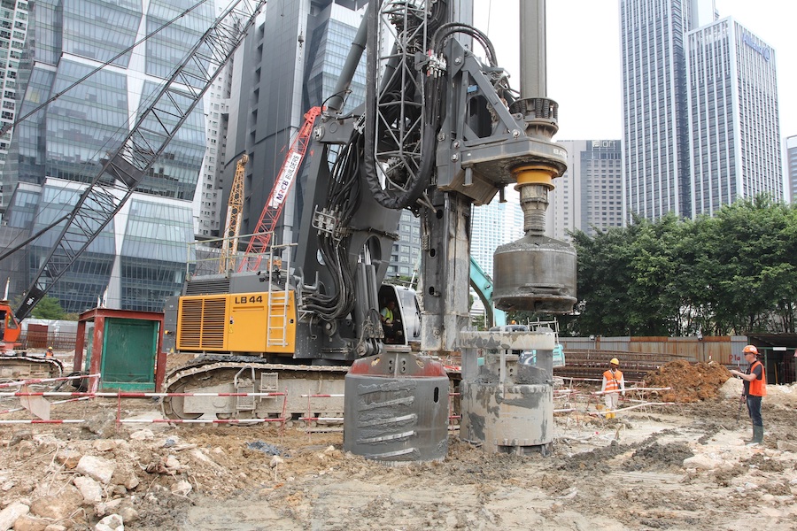
Field Boring Procedures
You want to ensure good logging and accurate field notes. You’ll want the logger to understand that a good field description must be recorded, since the field-boring log is critical to foundation condition analysis.
At the time of drilling, you’ll want to accurately record the maximum amount of information obtained from a boring—even if it does not seem important at the time. This record is the field boring log. The finished boring log is used in the preparation of the designer’s final report. It includes the field boring log data and the results of lab visual identification samples and lab classification tests.
Each organization will decide who logs the field information. Some companies will have an engineering geologist or trained technician work with the drill crew. Others may train the drill crew supervisor to log the borehole. The logger should consult with the driller as to changes in materials and operations while drilling.
Generally, the logger should be responsible for recording the following information:
- General description of each rock and soil stratum, and the depth to the top and bottom of each stratum.
- The depth at which each sample is taken, the type of sample taken, its number, and any loss of samples taken during extraction from the hole.
- The depths at which field tests are made and the results of the test.
- Information generally required by the log format, such as:
- Boring number and location.
- Date of start and finish of the hole.
- Name of driller (and of logger, if applicable).
- Elevation at top of hole.
- Depth of hole and reason for termination.
- Diameter of any casing used.
- Size of hammer and free fall used on casing (if driven).
- Blows per foot to advance casing (if driven).
- Description and size of sampler.
- Size of drive hammer and free fall used on sampler in dynamic field tests.
- Blow count for each 6 inches to drive sampler. (Sampler should be driven three 6-inch increments or to 100 blows).
- Type of drilling machine used.
- Type and size of core barrel used.
- Length of time to drill each core run or foot of core run.
- Length of each core run and amount of core per run.
- Recovery of sample in inches and RQD of rock core.
- Project identification.
- Notes regarding any other pertinent information and remarks on miscellaneous conditions encountered, such as:
- Depth of observed groundwater, elapsed time from completion of drilling, conditions under which observations were made, and comparison with the elevation noted during reconnaissance (if any).
- Artesian water pressure.
- Obstructions encountered.
- Difficulties in drilling (caving, coring boulders, surging or rise of sands in casing, caverns, etc.).
- Loss of circulating water and addition of extra drilling water.
- Drilling mud and casing as needed and why.
- Odor of recovered sample.
- Any other information the collection of which may be required by policy.

During progression of a boring, the field drilling personnel should only roughly identify and describe the soils encountered. Unfortunately, the drillers are typically assigned the task of exactly identifying and describing the soil samples. Soil samples should be sent to a lab as a driller’s expertise is in mechanical operation of the rig and preparation of pertinent data for the subsurface log. In addition, the visual identification test should not be done outdoors in an atmosphere subjected to the elements. Soil sample testing will provide the basis for later testing and soil profile development. That is why visual identification by a technician experienced in soils work is critical. This is of great importance where no laboratory testing is to be performed and design values are estimated on the visual description and SPT results.
When additional in-situ sample borings are taken they are sent to a soils laboratory for testing. Drilling personnel should exercise great care in extracting, handling, and transporting these samples to avoid disturbing the natural soil structure. Tubes should only be pressed – not driven with a hammer. The length of press should be 4 to 6 inches less than the tube length. Do not over press.
Pour a one-inch thick plug composed of a mixture of beeswax and paraffin to seal the tube against moisture loss. Before transport, fill the void at the upper end of the tube with sawdust and then cap and tape both ends. The most common sources of disturbance are rough, careless handling of the tube (such as dropping the tube samples in the back of a truck and driving 50 miles over a bumpy road). Exposing the tubes to temperature extremes (leaving the tube sample outside in below zero weather or storing in front of a furnace) will also cause disturbance.
Properly store the tubes for transport by keeping them upright in an insulated box partially filled with sawdust or Styrofoam to cushion them. Keep the tubes separated from each other (the way you pack glasses for shipment). Alternatively, extrude tube in the field. Carefully section the samples in 6 to 8-inch lengths, wrap in wax paper, and seal in a cardboard container (such as ice cream cartons) using liquid paraffin.
Roadway Soil Surveys
Soil survey explorations are made along the proposed roadway alignment for defining subsurface materials. This information is used in the design of the pavement section. It defines the limits of unsuitable materials and any remedial measures to be taken. Additionally, soil survey information is used in predicting the probable stability of cut or fill slopes.
Minimum criteria for soil surveys vary substantially, depending on the location of the proposed roadway, the anticipated subsurface materials, and the type of roadway. The following are basic guidelines covering general conditions. The engineer should visit the site to ensure that all features are covered. Generally, if a structure boring is close to a planned soil survey boring, the soil survey boring may be omitted.
- At least one boring should be placed at each 100-foot (30 m) interval. In general, borings are staggered left and right of the centerline to cover the entire roadway corridor. You may space borings farther apart if pre-existing information indicates the presence of uniform subsurface conditions. Add borings as necessary to define the limits of any undesirable materials or to better define soils stratification.
- In areas of highly variable soil conditions, add borings at each interval using the following criteria.
- For interstate highways, three borings at each interval, one within the median and one within each roadway.
- For four lane roadways, place two borings at each interval, one within each roadway.
- For roadway widenings that provide an additional lane, place one boring within the additional lane at each interval.
- In areas of cut or fill, where stability analysis is anticipated, place a minimum of two additional borings at each interval near the outer reaches of the sloped areas.
- In all cases, obtain at least three samples per mile (two samples per kilometer) or three per project (whichever is greater) for each stratum encountered. Each of the samples representing a particular stratum should be obtained from a different location, with sampling locations spread out over each mile (kilometer). Samples should be of adequate size to permit classification and moisture content testing.
- Obtain additional samples to permit LBR and corrosion testing. As a minimum, three LBR samples per mile (two samples per kilometer) or 3 per project whichever is greater per stratum of all materials should be obtained and tested. LBR samples should also be obtained of all strata located in excavation areas (i.e., water retention areas, ditches, cuts, etc.). Corrosion series samples should be obtained (unless no structures are to be installed) on a frequency of at least one sample per stratum per 1,500 feet (450 m) of alignment. When a rigid pavement is being considered for design, obtain enough samples to perform laboratory permeability tests.
- Borings in areas of little or no grade change should extend a minimum of 5 feet (1.5 m) below grade, drainage pipe or culvert invert level whichever is deeper. Every 500 feet (150 m), one boring should be extended to a nominal depth of 20 feet (6 m) below grade. The 20 feet (6 m) borings apply to projects with proposed buried storm sewer systems; project specifics may dictate adjustments. Borings may or may not include Standard Penetration Tests (SPT), depending on the specific project and its location.
- In areas of cut, borings should extend a minimum of 10 feet (3 m) below the proposed grade. If poor soil conditions are encountered at this depth, borings should be extended to firm materials or to a depth below grade equal to the depth of cut, whichever occurs Bag, SPT, undisturbed and core samples should be obtained as appropriate for analyses.
- In areas of fill, borings should extend to firm material or to a depth of twice the embankment height. Bag, SPT, and undisturbed samples should be obtained as appropriate.
- Areas of muck must be probed to delineate both the vertical and the horizontal extents.
Structures
Structure borings provide information about the subsurface materials to permit design of the structure foundations and related geotechnical construction. You can use the following general criteria on most projects. However, it is the engineer’s responsibility to determine appropriate explorations for each project.
The procedure for this is outlined as follows, with details for different types of structures given in the following sections:
- Progress the drill holes according to the recommendations given below for different types of structures. The drill holes may be advanced with casing, drilling mud, or continuous flight augers.
- Estimate the boring depth from existing data obtained during the terrain reconnaissance phases or, less preferred, from requested boring resistance data.
- Obtain standard split spoon samples at proper intervals or at changes in material.
- Record the standard penetration test data on each drill hole in accordance with ASTM D-1586. Regardless of the oft-cited frailties of the test, this is the most economical method presently available for procuring useful data.
- Instruct the drilling crew to perform a rough visual analysis of the soil samples and record all pertinent data on a standard drill log form. The disturbed spoon samples must be carefully sealed in plastic bags, placed in jars, and sent to the laboratory for analysis. Undisturbed tube samples must be sealed and stored upright in a shock proof, insulated container normally constructed from plywood and filled with cushioning material.
- Observe the water level in each boring and record the depth below top of hole and the date of the reading on the drill log for:
- Water seepage or artesian pressure encountered during drilling. Artesian pressure may be measured by extending drill casing above the ground until flow stops. Report the pressure as the number of feet of head above ground.
- Water level at the end of each day and at completion of boring.
- Water level 24 hours (minimum) after hole completion. Long-term readings may require installation of a perforated plastic tube before abandoning the hole.
A false indication of water level may be obtained when water is used in drilling and adequate time is not permitted after hole completion for the water level to stabilize. In low permeability soils, such as clays, more than one week may be required to obtain accurate readings.
- Designate a unique identification number for each drill hole to prevent duplication during later exploration phases.
Bridges
Perform at least one 2.5” (63.5 mm) minimum diameter borehole at each pier or abutment location. Stagger the hole pattern so that borings occur at the opposite ends of adjacent piers. Pier foundations or abutments over 100 feet (30 m) in plan length may require at least two borings, preferably at the extremities of the proposed substructure. For structure widenings, the total number of borings may be reduced depending on the information available for the existing structure.
- If pier locations are unknown, their probable approximate locations may be deduced based on experience and a preliminary design concept for the structure. If this is not possible, place borings at no more than 100-foot (30 m) intervals along the alignment. Additionally, for projects which include a water crossing that includes a pier in the water, locate at least one boring in the water when practical, depending on the width of the crossing.
- Borings should be continued until all unsuitable foundation materials have been penetrated and the predicted stress from the foundation loading is less than 10% of the original overburden pressure or until a minimum of 10 feet (3 m) of competent rock has been penetrated. If no data is available for predicting the foundation stress, extend the boring until at least 20 feet (6 m) of bedrock or other competent bearing material (N-values of 50 or greater) is encountered. (Scour and lateral requirements must be considered.)
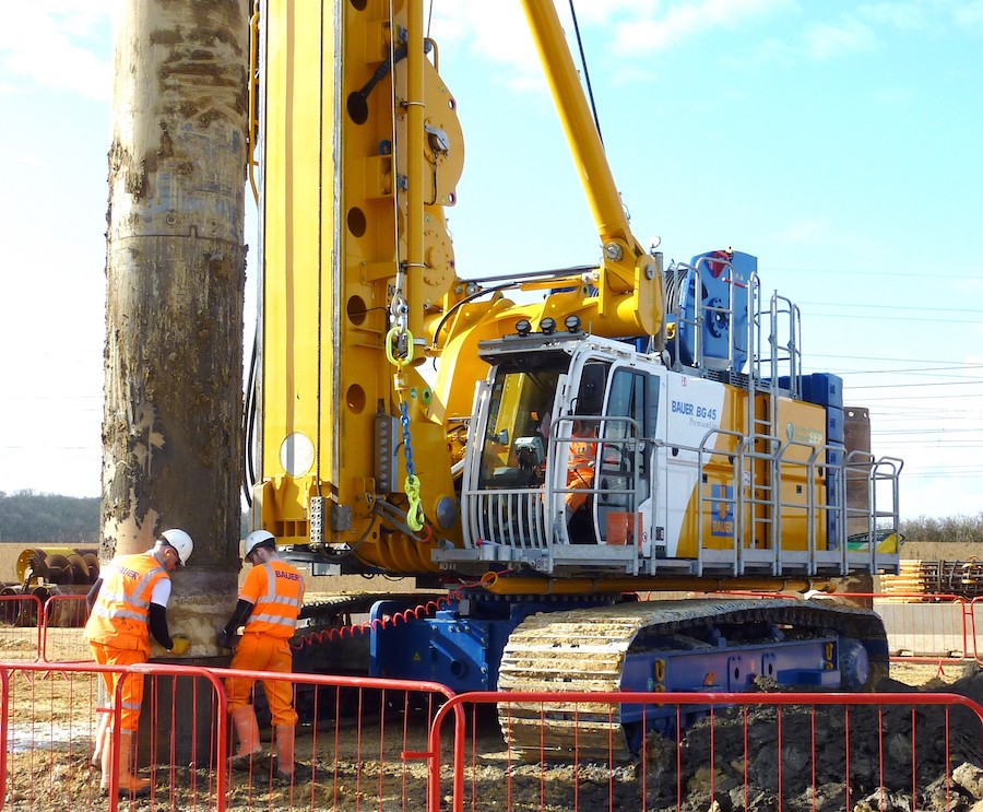
-

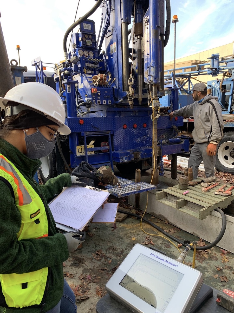
Standard penetration testing. Photo credit: GRL Engineers, Inc. When using the Standard Penetration Test, split-spoon samples should be obtained at a maximum interval of 2.5 to 3.0 feet (one meter) and at the top of each stratum. Continuous SPT sampling in accordance with ASTM D 1586 is recommended in the top 15 to 20 feet (5 to 6 m) unless the material is obviously unacceptable as a founding material. These spoon samples are “disturbed” samples generally not suited for laboratory determination of strength or consolidation parameters. Undisturbed Shelby tube samples should be obtained at 5-foot intervals in at least one boring in cohesive soils. For cohesive deposits greater than 30 feet in depth, tube sample interval can be increased to 10 feet. In soft clay deposits, in situ vane shear strength tests are recommended at 5 to 10-foot intervals.
- When cohesive soils are encountered, in situ samples should be obtained at 5-foot (1.5 m) intervals in at least one boring. Samples should be obtained from more than one boring where possible.
- When rock is encountered, successive core runs should be made with the objective of obtaining the best possible core recovery. SPT’s should be performed between core runs, typically at 5-foot (1.5 m) intervals.
- In-situ vane, pressuremeter, or dilatometer tests are recommended where soft clays are encountered.
- Corrosion tests are required on all new bridge projects. Minimally, one on the soil and one on the water should be done.
- In the case of water crossing, samples of streambed materials and each underlying stratum should be obtained for determination of the median particle diameter, D50, needed for scour
- For projects with large ship impacts, the pressuremeter test is recommended to be performed within seven (7) foundation element diameters below the deepest scour elevation at the pier location.
Approach Embankments
- At least one boring should be taken at the point of highest fill; usually the borings taken for the bridge abutment will satisfy this purpose. If settlement or stability problems are anticipated, as may occur due to the height of the proposed embankment and/or the presence of poor foundation soils, additional borings should be taken along the alignment. The first of these borings should be no more than 15 feet (5 m) from the abutment. The remaining borings should be placed at 100-foot (30 m) intervals until the height of the fill is less than 5 feet (1.5 m). Take the borings at the toes of the proposed embankment slopes as well as the embankment centerline.
- Continue borings until the superimposed stress is less than 10% of the original overburden pressure and unsuitable founding materials have been
- Sampling and in-situ testing criteria are the same as for bridges, above.
Retaining Walls
- At retaining wall locations, borings should be taken at a maximum interval of one per 150 feet (50 m) of the wall, as close to the wall alignment as possible. Extend borings below the bottom of the wall a minimum of twice the wall height or at least 10 feet (3 m) into competent material. This applies to all walls, proprietary systems, and precast and cast-in-place.
- Sampling and in-situ testing criteria are the same as for bridges.
Buildings
In general, one boring should be taken at each corner and one in the center. You may reduce this for small buildings. For extremely large buildings or highly variable site conditions, one boring should be taken at each support location. Other criteria are the same as for bridges.
Drainage Structures
- Borings should be taken at proposed locations of box culverts. Trenches or hand auger borings may suffice for smaller structures.
- For box culverts, borings should extend a minimum of 15 feet (5 m) below the bottom of the culvert or until firm material is encountered, whichever is deeper.
- For smaller structures, borings or trenches should extend at least 5 feet (1.5 m) below the bottom of the structure or until firm material is encountered, whichever is deeper.
- Corrosion testing must be performed for each site. Material from each stratum above the invert elevation and any standing water should be For drainage systems parallel to roadway alignments, tests should be performed at 1,500-feet (500 m) intervals along the alignment.
High Mast Lighting, Strain Poles and Sign Structures
- One boring should be taken at each designated location.
- Borings should be 50 feet (15 m) into suitable soil or 5 feet (1.5 m) into competent rock. Deeper borings may be required for cases with higher torsional loads.
- Other criteria are the same as for bridges.
Mast Arms Assemblies
- One boring (Auger, SPT or CPT) should be taken in the area of each designated location (for uniform sites a boring can cover several foundation locations).
- For mast arm assemblies an analysis and design must be done.
Tunnels
Due to the greatly varying conditions under which tunnels are constructed, establish investigation criteria for each project on an individual basis.
Borrow Areas
Test pits, trenches, and various types of borings can be used for exploration of potential borrow areas. Obtain samples to permit classification, moisture, compaction, permeability test, LBR, and/or corrosion testing of each material type, as applicable. The extent of the exploration will depend on the size of the borrow area and the amount and type of borrow needed.
Retention Ponds
Take a minimum of 2 borings per 40,000 feet2 (4,000 m2) of pond, with a minimum depth of 5 feet (1.5 m) below the deepest elevation of the pond, or until a confining layer is encountered or local water management criteria are satisfied. Perform a minimum of two field permeability tests per pond. Increase this number for larger ponds.
Sufficient testing must be accomplished to verify whether the excavated material can be used for embankment fill. In addition, if rock is to be excavated from the pond, sufficient borings and soundings are needed to estimate the volume of rock to be removed and the hardness of the rock.
View the complete article here.
What is the significance of soil mechanics in construction?
Soil mechanics is crucial in construction as it helps assess soil behavior, stability, and bearing capacity, influencing foundation design and overall project safety.
How does soil mechanics contribute to geotechnical engineering projects?
Soil mechanics is integral to geotechnical engineering, providing insights into soil properties, allowing engineers to make informed decisions on foundation design, slope stability, and overall project feasibility.