


Mastering Temporary Casing Installation in Unstable and Collapsible Ground
View the complete article here.
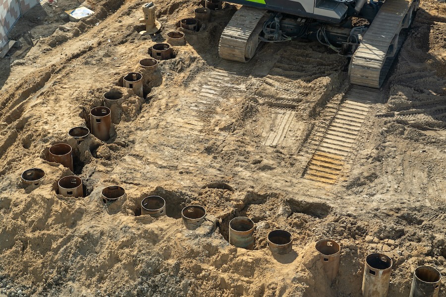
Collapsible soils such as loess or highly weathered residual materials can lose significant strength when wetted. Loose sands, silts, and gravels often cave in almost as quickly as the auger is withdrawn.
In these conditions—temporary steel casing becomes the essential tool for maintaining an open, stable borehole. It prevents sidewall sloughing and delivers a clean, high-quality drilled shaft ready for concrete placement.
When executed properly—casing installation supports high production rates and minimizes defects such as contaminated concrete, necking, voids, or expensive rework. Top drilled-shaft contractors approach temporary casing as a precision operation rather than an afterthought. They rely on careful planning, the right equipment, and precise field execution.
Understanding When Casing Is Essential
Before the first rotation begins, crews must evaluate the soil profile from borings and real-time site observations.
Unstable or collapsible layers, groundwater above the bearing stratum, or artesian pressure all signal the need for temporary casing. FHWA and state DOT specifications generally require it whenever the open-hole dry method cannot maintain borehole stability.
The same applies when caving, squeezing, or water inflow occurs during excavation. A practical field rule is to install casing if more than a few inches of sidewall fallout appears or if the hole will not hold verticality long enough for base cleaning and rebar placement.
Selecting the Right Casing Specifications
Choosing the appropriate casing starts with matching the diameter to the final shaft size while allowing adequate clearance for tools and concrete flow.
Wall thickness, typically ⅜ inch or heavier for large-diameter shafts, must resist buckling under external soil and hydrostatic pressure. Casing length should extend fully through the unstable zone and seat 3–5 feet into a stable bearing layer below.
Single-wall casings handle most projects efficiently. Segmental or double-wall options perform best in very deep or obstructed conditions. Adding cutting teeth or carbide-tipped shoes on the leading edge improves penetration when boulders or dense layers are anticipated at the tip.
Every section should be inspected for roundness, dents, and corrosion before use. Out-of-round casings create major extraction difficulties later in the process.
Proven Installation Methods
Contractors generally rely on one of two effective approaches depending on site conditions.
In the first method, crews drill the upper unstable zone using slurry or dry techniques first. They then lower the casing into the oversized hole and advance it into the stable stratum with a Kelly-bar twister or casing adapter applying controlled torque and crowd. This works well when the upper soils will stand briefly.
The second, and frequently preferred, method advances the casing ahead of excavation—particularly in highly collapsible or running sands. Here the casing remains 1–3 feet ahead of the excavation tool at all times, virtually eliminating cave-in risk.
Advancement can be achieved with a vibratory hammer for speed on non-sensitive sites, an oscillator or rotator for low-vibration precision in urban or vibration-restricted areas, or a rotary drive with a dedicated casing adapter.
Field Execution Sequence
Successful installation follows a disciplined sequence that rewards attention to detail.
Crews begin by positioning the first casing section plumb and level. They then use the rig’s crowd and rotation (or vibration) to embed it 2–4 feet into the ground.
As drilling continues, the casing must stay ahead of the tool while verticality is monitored constantly. Deviations greater than 1% can lead to alignment problems that are difficult to correct later.
Once the stable layer is reached, additional crowd and rotation create a tight seal at the casing tip to prevent water or soil from piping up around the exterior during concreting.
After excavation, the base receives thorough cleaning with a cleanout bucket or airlift—leaving no more than ½ inch of loose material or sediment at the toe. The rebar cage is then lowered, centered, and supported with spacers to maintain required concrete cover.
Tremie concrete placement begins immediately from the bottom up, with the pipe kept embedded at least 5–10 feet in fresh concrete at all times. Extraction follows while the concrete remains fluid—typically within 30–60 minutes of placement start—using the rig’s extraction force, oscillator, or vibro equipment.
Throughout extraction, a head of concrete inside the casing must remain at least 5–10 feet above the external groundwater level to counterbalance hydrostatic pressure.
Essential Support Equipment and Techniques
Certain pieces of support equipment dramatically improve efficiency and safety on challenging jobs. Key items include:
- Oscillator or rotator systems that excel in full-depth or deep unstable zones because they twist the casing with minimal vibration.
- Reinforced tops on casings where clamps or jaws engage to prevent deformation under load.
- A backup extraction plan such as hydraulic casing jacks or a second rig if the casing becomes stuck.
- Spare cutting teeth, twister bars, and casing adapters kept readily available on site to minimize downtime.
Avoiding Common Pitfalls
Even well-planned operations can encounter issues if key details are overlooked. The most frequent problems include:
- Poor seal at the casing tip, which allows water or soil inflow during concreting (extra crowd and rotation at seating usually resolves this).
- Extracting too late, which permits concrete to set around the casing.
- Over-excavating inside the casing, which can cause base instability or heave.
- Leaving the casing in place longer than necessary, which reduces side friction.
- Neglecting verticality, which produces out-of-plumb shafts that fail inspection.
In extremely difficult conditions, such as strong artesian flow or highly running sands, a hybrid approach combining temporary casing with polymer slurry often provides the safest and most productive solution. When pulling the casing risks defects or the engineer requires support through weak zones, permanent casing may be the better choice.
Achieving Consistent Success in Difficult Ground
Mastering temporary casing installation in collapsible and unstable soils ultimately comes down to sequence, timing, and meticulous attention to detail.
Contractors who treat the process as a precision operation consistently deliver cleaner shafts, experience fewer change orders, and maintain higher production rates even when the ground conditions are at their most unforgiving.
Thorough planning combined with experienced crews and the right equipment turns one of the industry’s most challenging tasks into a reliable, repeatable process.
Sources:
Federal Highway Administration. (2018). Drilled Shafts: Construction Procedures and Design Methods. Geotechnical Engineering Circular No. 10 (FHWA-NHI-18-024). U.S. Department of Transportation, Federal Highway Administration, Washington, DC.
Brown, D.A., Turner, J.P., & Castelli, R.J. (2018). Drilled Shafts: Construction Procedures and Design Methods (FHWA GEC 10). Federal Highway Administration.
ADSC: The International Association of Foundation Drilling & Deep Foundations Institute. Drilled Shaft Inspector’s Manual.
View the complete article here.
What is temporary casing used for in drilling and foundation projects?
Temporary casing is used to stabilize boreholes and prevent soil collapse when working in unstable or loose ground conditions.
When should temporary casing be installed during drilling operations?
Temporary casing should be installed when ground conditions are prone to caving, groundwater intrusion, or borehole instability during excavation.