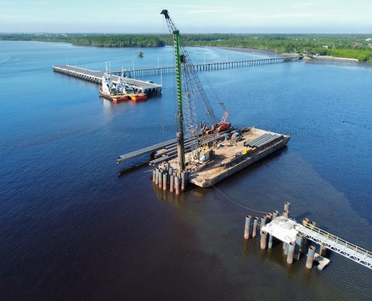
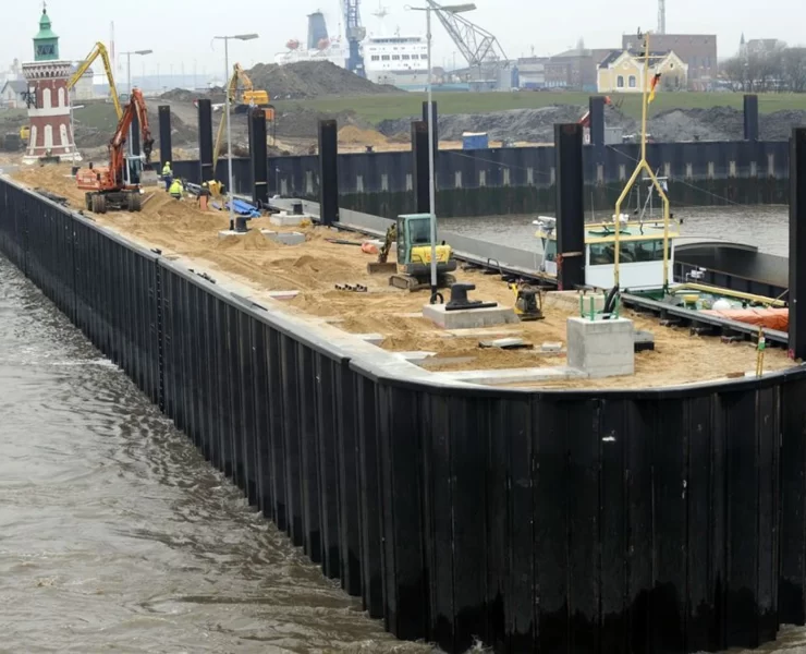
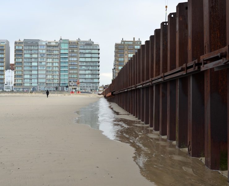
Pile Guide Part 2 – Sheet Piles
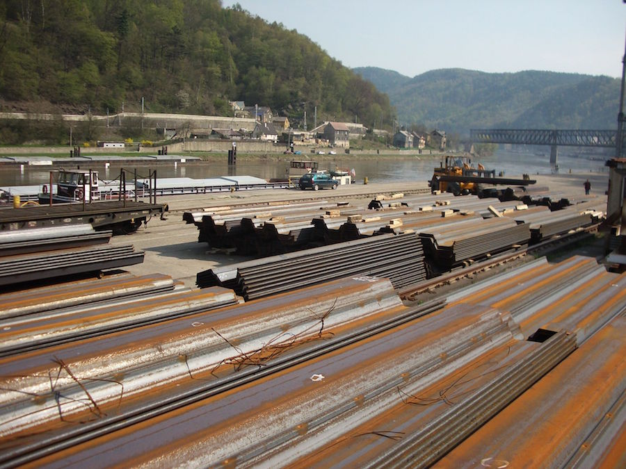
View the complete version here.
Introduction
Sheet piles are, by definition, structural units which when connected one to another, will form a continuous wall, generally for retaining earth or excluding water. Interlocking devices formed as part of the manufactured product provide the wall continuity. Sheet piling has been made of steel, concrete, wood, aluminum and other materials. Steel is by far the dominant choice, due to ready availability, relative strength, and ease of handling, storage and installation, although the use of other materials is increasing.
Steel Sheet Piling
General Information
- Steel sheet piling is generally delivered to the project from the mill or from field-stocks in preordered lengths and stacked, ready for use.
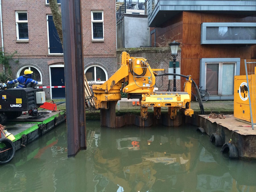
- Individual pieces or pre-interlocked pairs are installed by driving using impact hammers, vibrators or by water jetting.
- Sheets are “threaded” one to another during the setting and driving operation so that a continuous, relatively soil and watertight wall is formed.
- In functioning as a wall, the sheet piling acts as a beam under load and therefore must resist bending.
- Sheet pile shapes have evolved over the years from simple channel sections with crude fabricated locks, to “U” shapes with integral, rolled-on interlocks, to today’s wide range of high strength “Z” shapes.
Applications
- Artificial islands
- Bulkheads-including dock walls for marine terminal facilities in water
- Cofferdams – temporary, in water or on land to permit excavation for and construction of permanent works
- Cut-off Walls – in connection with earth or concrete dams or dikes to retard seepage
- Dry Dock Walls
- Retaining Walls
- Seawalls, Flood Walls, Dikes, Jetties, Groins
- Navigation Lock Walls and other large navigation structures
- Mooring and Turning Cells, Dolphins.
- Barge Docks – Consisting of Individual Cellular Structures
- Bridge Protection Cells – to protect bridge piers from shipping collisions.
Types
- Steel sheet piling is manufactured in three basic configurations – “Z”, “U” and “straight” (flat).
- Historically such shapes have been “hot-rolled” products of structural mills. Like other shapes such as beams or channels, they are formed during a succession of passes through different roll stands of the mill. In the case of sheet piling, the rolled-on clutch or interlock is an additional special feature of sheet piling production.
- Some producers use a cold-forming process in which hot-rolled sheet steel is fabricated into traditional sheet piling shapes manufactures some sheet piling shapes.
- These new additions to product availability contain interlocks that are considerably different from the hot-rolled products. Cold-formed sheeting is manufactured from a hot-rolled coil of steel, and then is slowly fed through a series of rollers, which gradually bends or forms the steel into its designated shape.

Z-Type Shapes
- The Z type configuration is generally considered the strongest and most efficient.
- These shapes resemble wide-flange beams, having a web and two flanges. The interlocks are located out on the flanges at maximum distance from the neutral axis, and this provides a high section modulus for resisting bending moments.
- Because of this, Z-shapes have traditionally been used for heavier construction projects. However, they are now complemented by the arch or U shapes for lighter work, and lightweight Z-shapes have been also introduced into the marketplace.
- The interlocks of hot-rolled Z-type sheet piling are designed for free sliding and integrity during driving. Since most Z-piles are used to construct straight walls, there is generally no need for any guaranteed swing or deflection between sheets although there is almost always some attainable if needed, except perhaps in very long sheets.
- Sheet piling produced in the United States has been rolled with a “ball and socket” interlock design. Historically, it has been recommended that these be driven so that the ball of the interlock was leading. The socket then had a pre- cleared path into the ground. The importance of this recommendation has been properly questioned and many walls have been successfully installed without following this procedure. These inter locks are not designed for applications where resistance to tension is important.
- Although there are some general similarities in the styles, the interlocks provided on Z-piling available from European and Japanese producers vary with the producer.
- In general, whether the piling be foreign or domestic, the user should not assume sheets can be mixed on the job simply because the locks “look” the same. Tolerances may vary from producer to producer.
- The interlocks of the heavier piling sections may not interlock with lighter ones from the same producer.
- Because of their inherent strength, Z-piles can be handled and shipped with less exposure to possible damage than some other style sheets. These interlocks do not lend themselves well to splicing and splices should be avoided if possible.
- Interlocks should be reasonably free sliding, that is, the pile should run to grade of its own weight when interlocked with its neighbor.
- Z-piles are generally used in constructing straight wall structures – cofferdams, bulkheads and retaining walls.
- Sheet piling can be pulled after temporary use, the interlocks cleaned and reconditioned and the sheets used again for similar applications.

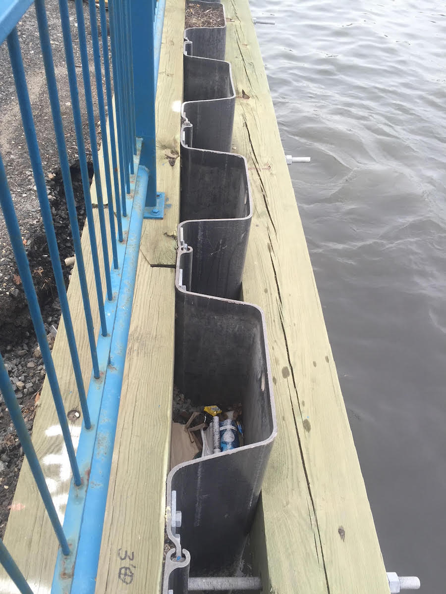
 Arch Web and U-Shape Piling
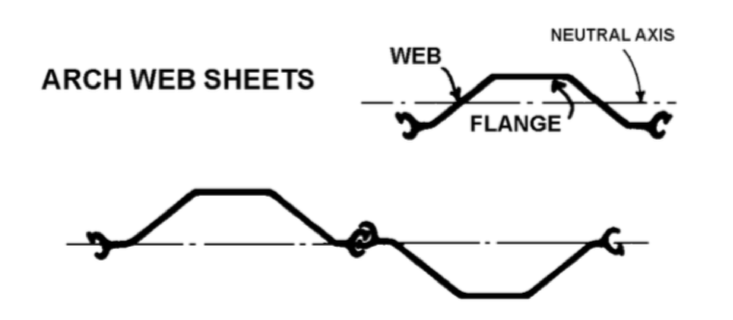
- These shapes resemble the hot-rolled channel sections produced on structural mills.
- The interlocks are formed on the web ends and interlock with their opposing mate along the centerline of the wall.
- These shapes are not considered as efficient as the Z-type for the equivalent weight.
- Interlocks of domestic arch-web sheet piling were of the “thumb and finger” design. The thumbs of opposing sheets were threaded into the sockets formed by the thumb and curved finger providing a strong grip and one of relatively good water and soil tightness.
- The standard installation procedure calls for reversing every other sheet.
- The German engineer Larssen based interlocks of foreign U-type piling on an historical interlock design. This interlock is best described as a “double-clutch” design and is considerably less complex than the thumb and finger design of American manufacture.
- Arch web and U-type sheets may be somewhat easier to splice for extending lengths than Z-sheets. In addition, since these locks are somewhat looser, there is a smaller chance of binding during the setting and driving operation when dealing with extremely long lengths.
- The interlocks of the series of arch web shapes produced by cold forming are of the “hook and grip” type previously described.
- Arch-web shapes have been used primarily for lighter construction, for example, trench shoring, shallow cofferdams in water or on land, light bulkheads for marinas or river port facilities, shallow retaining walls and cut-off walls (where strength is less important than interlock integrity).
- Large “U” shapes have traditionally been popular in other parts of the world for all classes of construction, probably because Z- type sheets are a more recent addition overseas.
Flat and Shallow Arch Web Types
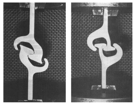
- Whereas the Z-type and Arch-web type piling are used in applications where their resistance to bending is the “primary” consideration, there is another series of piling shapes that find their application in circular, freestanding structures called Filled Cells.
- The sheets used in these applications are subjected to hoop tension from internal pressure exerted by the retained soil, rather than bending. As a result, the ability to transfer this stress across the interlocks is most important and these sheet pilings have interlocks specifically designed for such loads.
- They are purposely designed as flat profiles so that they will not elongate and flatten across the arch as would be the case with the arch-web or Z-sheets.
- The interlocks of this group are of the thumb and finger type. Opposing thumbs are threaded into the slots formed by the thumb and finger and under hoop tension. The sheets then form a continuous circular wall that is earth tight and relatively watertight.
- The manufacturer guarantees the strength between interlocked sheets so that designs can be prepared which will provide adequate safety factors against failure.
Grades of Steel Sheet Piling
- In the United States, sheet piling is specified by reference to the ASTM standard. The basic grade is A- 328. This requires that the yield strength be a minimum of 38.5 ksi.
- Higher strength steels are available in ASTM Grades 50 and 60 which have minimum yields of 50 ksi (345 MPa) and 60 ksi respectively. This permits possible economies in meeting calculated bending moments by combining lighter sections with higher strength steel.
- An additional grade of steel for piling has been developed for possible use where corrosion from salt water is a consideration. This grade is ASTM A-690 which is a 50 ksi (345 MPa) yield steel and also of a formulation which has demonstrated increased life in salt-water splash zones compared to regular grades.
- Allowable stresses for design of sheet pile structures are generally based on about 65% yield (25 ksi for the standard A 328 grade). Proportionately higher allowable stresses of 32 ksi and 38 ksi respectively are allowed for the higher strength grades. Some increase is generally allowed for temporary stresses.
HZ Walls
- Wide flange beams are generally considered the most efficient structural units for handling loads that result in bending moments developing.
- A wall constructed entirely of interlocking wide-flange beams would be difficult to construct and would be inefficient from the standpoint of wall face coverage.
- A system has been developed which combines wide flange beams with Z-type sheet piling to provide a wider range of section moduli. The basic layout combines one wide flange with two light Z-shapes as the basic unit.
- By including wide flange in the unit, elevated section moduli, well above anything attainable from plain sheets, can be realized. The system is not quite as efficient as a conventional wall when bending moments are less than about 2 million inch-pounds, since these can be handled with “as-rolled sheets” and high strength steel.
- An alternate to the proprietary HZ system for deep-water design is to utilize wide flange beams to stiffen a conventional Z-pile wall.
- Either the beams are welded to pairs of Z-sheets or portions of the Z sheet are slit and welded to the beam flanges to provide an interlock. Very high section modulus can be obtained using these methods.
Anchor Systems
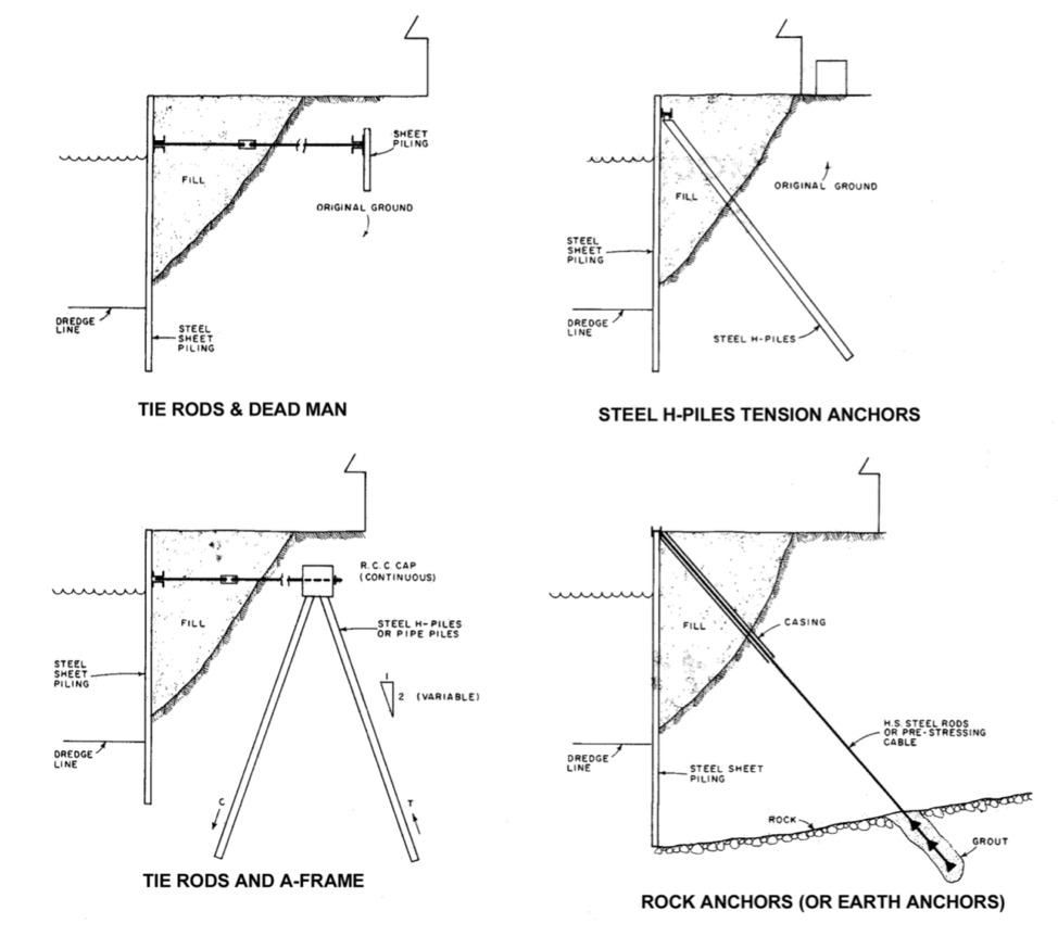
- The top support for the sheet pile wall is provided by the anchor system.
- The reaction obtained during the design is transferred from the wall to the anchors by structural steel wales generally fastened to the rear of the wall by bolting.
- Occasionally, wales are located on the outboard face of the wall but for working bulkheads, they are best placed on the inside face. Wales generally consist of two channels, back to back, with spacers.
- Tie rods, spaced at regular intervals, extend from the face wall through the wales to an anchor wall or anchor piles to the rear. Depending on the loads per rod, tie rod spacing is generally an even multiple of the driving distance (width) of a pair of sheet piles to facilitate installation.
- Tie rods are fabricated from steel bars, the ends upset to provide additional metal at the threads, and assembled on the job with holding plates, washers, nuts and turnbuckles.
- Tie rods should be located as close to the low water elevation as possible to reduce the span between supports, but should be above water to facilitate installation.
- The dead man or rear anchor wall should be located well outside the influence of the active failure zone of the soil against the front wall.
- Tie rods should be coated and wrapped to protect them from corrosion losses and protected from overstressing due to ground settlement.
- Other methods of anchoring bulkheads include rock or earth anchor systems and H-pile tension piles. Earth anchors are useful where there is not sufficient space behind to install a more conventional tie rod system.
- Earth anchors utilize slant-drilling techniques to install high strength steel rods or cable between the wall and rock or stable soil at some lower elevation. The anchor is grouted in place and a pre-test of its capacity is possible during the prestressing or post- tensioning phase.
- Steel H-piles may be driven on a batter and fastened to the wale system. They function as tension piles.
Temporary Cofferdams
- Steel sheet piling is virtually the only means for a contractor to keep water out of a construction site while the permanent structure is built in the dry.
- On land, other methods such as slurry walls and steel soldier beam walls have replaced sheet piling for temporary construction.
- The exception would be where ground water must be retained or to comply with legal requirements for safety.
- Straight wall cofferdams are designed using techniques similar to bulkheads and retaining walls. The cofferdam consists of a closed square or rectangular wall of sheet piling. An internal system of wales and struts provide support. On land, earth or rock anchors keep the inside of the cofferdam clear for working ease. Out in the water however, conventional bracing systems of walers and struts are still necessary.
- In river cofferdams, external water pressure is the dominant load and removes a lot of uncertainty from the load assumptions since the loading is triangular at 62.4 pounds per foot of depth.
- Below excavated elevation, the pressure consists of submerged soil and water, which increases the pressure. The sheeting is designed as a beam on multiple supports. Loading conditions both during construction of the cofferdam and after dewatering must be considered. Stability of soil under and in front of the wall should also be examined for seepage effects. Internal bracing is spaced so that the sheet piling will not be overstressed.
- Moment calculations can be based on continuity over the supports. Reactions from the sheeting provide loads on the wales, which are designed as beams on supports. Loads on wales should include end thrust from the other members in the tier. Cross struts are designed as columns and located so that they do not seriously interfere with the work inside.
- Circular cofferdams with internal ring wales and no cross struts have sometimes been constructed where it has been necessary to keep the interior clear. Wales have been fabricated of steel or have been of cast in- place reinforced concrete.
- Several serious collapses of steel ring-wale braced cofferdams in water have occurred due to incorrect assumptions regarding the nature of stress distribution in the wales. Experienced designers should work on these applications.
Aluminum Sheet Piling
General Information
- Aluminum sheet piling has been available since 1969 in various forms and has had an excellent success rate during this period in both salt and fresh water environments.
- There are several important questions to be addressed when the choice of an aluminum sheet pile wall is being considered:
-
- It is strong enough?
- How long will it last?
- Will it look good?
- Is it functional?
- What are its initial costs and total costs over its life?
- Is it acceptable to the owner?
- One of the most significant advantages of aluminum sheet piling systems is its light weight. It has one of the most efficient strength to weight ratio of any type of building material.
- The ease of handling the relatively lightweight sheets, cap and hardware is a pleasant surprise to most contractors who are new to the use of aluminum piling.
- It allows the installer to work in tight spots that otherwise might be impractical from a cost standpoint with other types of piling materials.
- Historically, almost 90% of all aluminum piling applications have been in a saltwater environment, and generally without protective coatings. If care is taken in properly applying the material to the site, protective coatings will normally not be required.
- There are five important areas, which should be thoroughly addressed when considering aluminum sheet piling.
- Material specification
- Corrosion
- Construction suggestions
- Design principles
- Engineering data
Corrosion
- Probably the most common question asked about aluminum sheet piling is “will it work in this environment?”
- Aluminum alloys have been selected as materials of construction in many fields because of their ability to resist corrosion.
- Aluminum’s ability to resist corrosion by atmospheric weathering has been well demonstrated by its application in agriculture, industrial and residential roofing, siding and other building materials for many years.
- Aluminum’s resistance to corrosion both by fresh and salt waters can be shown by its many applications in ships, pleasure boats, irrigation pipe, heat exchangers, sewage disposal plants, rain carrying equipment, etc.
- Experience has also been gained over the years from installations of culvert sheeting and buried pipelines, which indicate that aluminum will perform satisfactorily in contact with many soils.
- Corrosion of aluminum (as well as other structural metals) is electrochemical in nature and involves the ow of electric current between various anodic and cathodic regions. Several major factors basic in determining this ow of current and the resulting corrosion are:
-
- Alloy constituents
- Metallurgical and thermal treatments
- Effect of pH
- Galvanic corrosion (dissimilar metals)
- Stray currents
- Soil resistivity
- There is no absolute “safe” method for testing soils. On a “normal” homeowner lot, one can easily miss an “unsafe” area of bad soil. The best suggestion is to take soil samples at the left, center and right sides along the intended bulkhead installation line. One sample in the center back from the wall line should also be taken. Two water samples should be taken also at the one-third points. These suggestions assume the natural ground to be homogeneous throughout the property. If the natural soils are not homogeneous, the same procedures should be followed for each type of soil present. Heavy metals should be tested for if you suspect their presence.
- If the test results show either the soil or water to be outside the “safe” ranges, as discussed previously, the decision is then left to the designer to either use protected aluminum, non-protected aluminum or no aluminum.
- If time permits while applying for a Corps of Engineers permit, install a section of sheeting in the ground along the intended bulkhead line and remove the sample in 2 to 3 months time. This should provide sufficient evidence of corrosion for one to make a reasonable conclusion as to the suitability of aluminum for that site.
Vinyl Sheet Piling
General Information
- Vinyl sheet piling can be applied in a wide variety of applications. It is lightweight, simple to set and install, resistant to environmental attack and can be configured in various colors. It was designed to be:
-
- Weatherable
- Corrosion resistant
- Unaffected by fungi and marine borers
- Environmentally friendly
- Easy to install
- Cost effective
- It is ideal for the lighter bulkheads that are typical with residential, recreational and marina construction. Vinyl sheeting can also be used for Navy walls as well.
Configuration
- Vinyl sheet piling is generally manufactured by continuous extrusion. This is the same process used to form PVC pipe. The raw material, plastic resin compound, is melted and pushed through a die. This die shapes the plastic into the desired cross section. The shape is then cooled and cut to the desired length.
- The individual sheets have interlocking male and female edges. The interlocking edges are extruded as part of the sheet to insure continuity.
- Vinyl sheeting is available in a number of configurations. The most common configuration is a Z-sheet type, which is similar to steel piling. Such sheets are made to be driven two at a time and, as is the case with their steel counterparts, offer a high section modulus.
- Since it is extruded, vinyl sheet piling can have a wider variety of sections than rolled steel sheeting. Vinyl sheet pile manufacturers take advantage of this advantage and frequently include stiffening ribs and/or thickened corners. The configuration of these stiffening elements varies with the manufacturer.
- Another configuration that is common with vinyl sheet piling is an “AWL” configuration, which combines the high section modulus of Z-sheeting with the ease of interlock alignment of at and U-type sheeting. In fact, it is in effect two U-sections put together.
- AWL sections also eliminate interlocks and thus potential leakage. When installed by vibratory drivers, however, setting the clamp arrangement for multiple sheet driving can be difficult due to the physical layout of the sheeting.
- As is the case with other sheeting, vinyl sheeting requires transition pieces such as corners and intersections. These are customized for the other sheeting the manufacturer makes.
Material
- Vinyl sheeting is made of a modified polyvinyl chloride (PVC), which makes it suitable for most marine environments and not subject to leaching, corrosion or similar deterioration mechanisms.
- Tensile strength for this material is approximately 6-7 ksi15 (41.3-48.3 MPa), with an initial modulus of elasticity of 350-400 ksi (2.41-2.76 GPa.)
- It cannot be overemphasized, however, that with plastics of any kind material properties cannot be applied as simplistically as with metals.
- Tensile strength of the material, for instance, can vary both with the way the sheeting is loaded (purely tensile vs. flexural loads) and with time.
- Time variation is also significant with the modulus of elasticity. It is important to follow the manufacturer’s recommendations on loading, and in many cases the manufacturer will specify a maximum moment per foot or meter of sheeting wall as opposed to allowing the designer to compute the maximum fiber stress in flexure.
- The relatively low values of strength and modulus of elasticity given above are very important to consider in the design of vinyl sheet walls.
- Not only is it important to consider the strength of the material but also that it is subject to greater deflection than other types of sheeting as well.
- Designers will realize that, as support spans increase, wall deflection will become the controlling aspect of the design.
Installation
- Vinyl sheet piling can be installed using a variety of equipment types, which include:
- Vibratory hammers, either excavator or crane mounted. Vibratory plate compactors are also used, but these are exclusively excavator mounted. It is important when using a plate compactor to keep a steady, downward force on the pile and vibrator during driving.
- A portable air-compressor or hydraulic jackhammer with a sheet shoe. This is only suitable for short sheets and is generally used by occasional installers.
- A drop impact hammer, either land-based or barge-mounted.
- A water jet fed by a high output pump, either held by hand or suspended from a crane.
- As with other types of sheet piling, vinyl sheet piling is best set before being driven. Because it is lightweight, when safety conditions permit it can be set by hand. It can also be installed with a crane or excavator if the conditions require.
- The selection of an installation method is a matter of both jobsite conditions and contractor preference. However, as with any driven pile, the preparation before driving is frequently as important as the driving itself.
Wood Sheeting
General Information
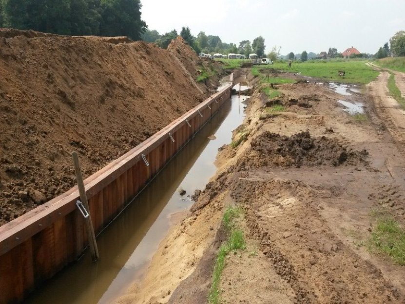
- In its simplest form, wood sheet piling can consist of a single line of boards or “single-sheet piling” but it is suitable for only small excavations where there is no serious ground water problem.
- In saturated soils, particularly in sands and gravels, it is necessary to use a more elaborate form of sheet piling which can be made reasonably watertight with overlapping boards spiked or bolted together, such as the “lapped-sheet piling” or “Wakefield” system.
- Wakefield sheeting consists of three planks 2” (50.8 mm), 3” (76.2 mm) or 4” (101.6 mm) thick and 12” (304.8 mm) or more wide, bolted and/or spiked together with the centerpiece an inch or more ahead of the others to form a tongue and groove. For most Wakefield assemblies, timbers should be surfaced on all four faces.
- In areas where steel sheet piling may not be available, Wakefield Piles are useful; this system was in wide use before the advent of steel sheet piles.
- For the driving case, the forward bottom edge of the wood can be beveled to force the sheet being added tightly against the in-place units. Wakefield or similar piles may be driven with a small conventional pile hammer or a heavy, hand-held air hammer or “paving breaker.” A vibratory earth compactor has been successfully used for vibrating lightweight sheet piling, as have been excavator mounted vibratory hammers.
Concrete Sheet Piling
General Information
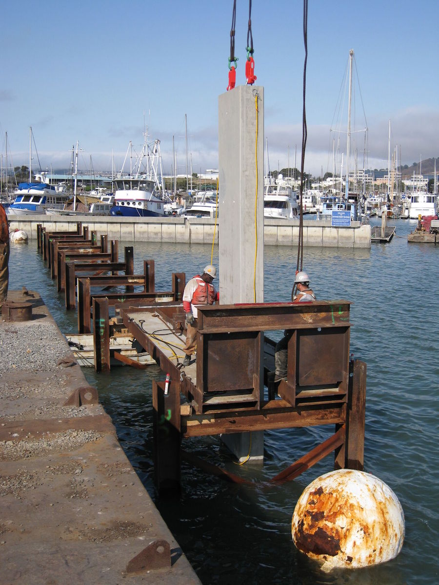
- For sea walls, groins and other waterfront structures, precast concrete sheet piles are often economical.
- They are normally used in situations where the precast members will be incorporated into the final structure or are going to remain in place after they fulfill their purpose.
- Precast concrete sheet piling is usually made in the form of a tongue and groove section.
- The individual pieces vary in width from 18” (457.2 mm) to 24” (609.6 mm) and in thickness from 8” (203.2 mm) to 24” (609.6 mm).
- They are reinforced with vertical bars and hoops in much the same way as precast concrete bearing piles.
- For seawater contact especially, prestressing is most desirable, as the minor cracks are kept closed so salt does not get to the reinforcing. This type of sheeting is not watertight, but the spaces between the piles can be grouted.
- Tongue and groove design, or a slot for grouting, will help to make the wall watertight. The slot would have to be washed out after pile installation and grout forced into the opening. For driving, a bevel of about 30o at the bottom on the leading edge of the pile will force the section being added tightly against the wall already in place.
- In order to provide a watertight precast concrete sheet pile, two halves of a straight steel web sheet pile, which has been split in half longitudinally, are embedded in the pile.
- Jetting is frequently used to install concrete sheet piles in sand. The pile must be installed while jetting, as the jetted hole may not stay open.
Hybrid System: Concrete and Vinyl Piling
General Information
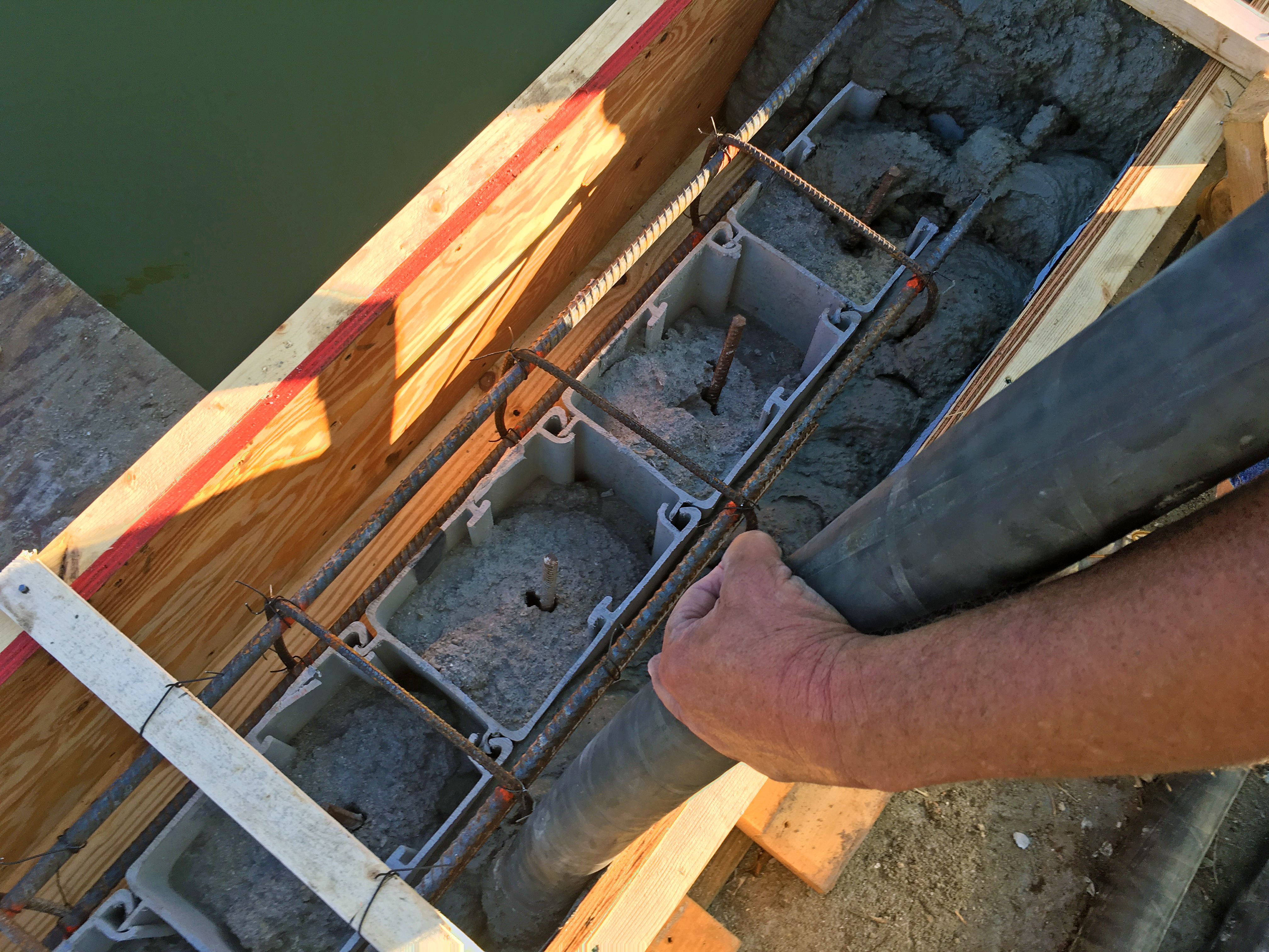
- The latest technology for sea walls is a hybrid system that combines the benefits of a strong steel-reinforced concrete wall with the benefits and protection of vinyl sheet piling.
- The individual vinyl sheet piling pieces are dual-interlocking, u-shaped and 12” (304.8mm) wide by 8” (203.2mm) deep and extruded to custom lengths. The system of modular parts provides continuous integrity throughout turns and radiuses. In addition, return walls can be installed from anywhere on the wall surface.
- When the vinyl sheet piling u-channels are joined together, they create a hollow cell in the middle in which to pour-in-place, steel-reinforced concrete.
- The u-channel design provides a flat, appealing surface similar to concrete and makes forming the cap easier.
- One of the benefits of the hybrid system is that the steel and concrete are encased inside the vinyl which protects it from salt water corrosion to provide a longer-lasting wall.
- Depending on the wall strength requirements, engineers can design with various strengths of steel and concrete.
- Vinyl sheet piling can be carried by hand and installed with light-duty equipment, allowing installation of strong and tall walls in even tight project areas. This system makes it easier to design and install walls with taller exposures.
- Unique to this hybrid u-channel design is being able to pin-pile in rocky soil conditions.
- Same standard installation procedures and equipment for vinyl sheet piling apply and can be installed in front of old concrete walls or a new wall can be installed.
View the complete version here.
What are the advantages of using cold-formed steel sheet pile over hot-rolled steel sheet pile?
Cold-formed steel sheet piles offer advantages such as easier driving, looser interlocks for efficient threading, and better performance in temporary applications due to their ease of handling.
How do Z-type sheet piles differ from Arch Web and U-Shape sheet piles, and in which applications are they commonly used?
Z-type sheet piles, known for their high section modulus, are preferred for heavier construction projects, while Arch Web and U-Shape sheet piles are often used for lighter applications like trench shoring, shallow cofferdams, and marina bulkheads.


 Arch Web and U-Shape Piling