Chapter 3 – Installation Equipment
For a complete version of this document click here.
3.1. Overview
Over the years, technology has advanced toward the development of larger and faster hammers. These developments included rams that were raised by ropes through human or horse muscle, those hoisted by steam winches or powered by steam, air, or hydraulic pressure, and finally the diesel hammer. Double acting hammers were developed in order to speed up operations. Hammers from all stages of this technological history are still encountered on construction sites. This section describes these various types of pile hammers.
If the only purpose of a hammer were to advance the pile into the ground, then the force-time characteristics of the hammer blow would not be so important. However, the vertical advance of a pile under a given hammer blow can be used as a measure of the pile’s bearing capacity. Thus, the hammer takes on a second function as a piece of testing equipment. The hammer’s interaction with the pile-soil system can be both modeled before driving (wave equation analysis) and monitored during pile installation (pile driving analyzer.) These methods are used to both control driving stresses and estimate the load capacity the pile. From this, field inspection has two important purposes:
• Ascertain that the hammer conforms to certain minimal standards.
• Record observations on hammer and driving system performance.
These two functions will enable the engineer to reduce the uncertainty in his or her interpretation of pile behavior. Furthermore, better productivity plus a reduced likelihood of construction claims can be expected.
3.1.1. Overview of the Driving System
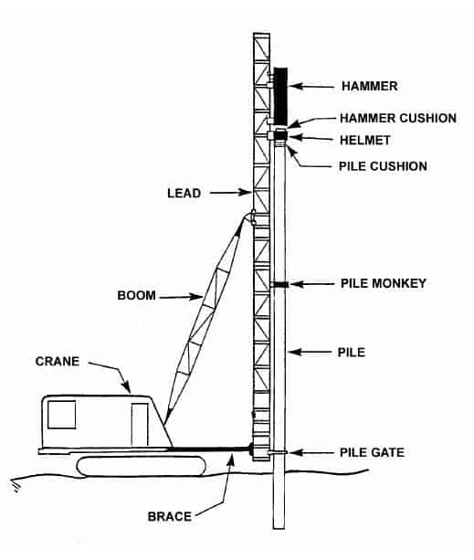
The driving system consists of the following components (see Figure 3-1):
• The lead, also called the set of leads, sometimes including a brace that allows for the adjustment of the lead angle.
• The hammer cushion, which protects both the hammer and the pile from excessive stress. Hammer cushion materials are relatively soft compared to steel. Usually, a striker plate protects the cushion.
• The helmet, which aligns the pile head and hammer. It is usually a steel casting.
• The pile cushion. This is only needed on concrete piles, and usually consists of several layers of plywood.
All components of the driving system have some effect on the performance of a hammer and/or how the hammer transfers its energy to a pile.
3.1.2. Equipment Selection
Hammer selection may be the most important aspect of pile installation. In some installations only one hammer type may be applicable for the pile-soil combination, while for others several types may be suitable. Evaluation must consider the need to use pile penetration rate as the means to end driving, the ability to drive the pile without structural damage or reducing soil capacity, the ability to obtain penetration rates within the desired band, and the realization that some hammer types may cause reduced capacities for identical pile lengths. In general, wave equation analysis supplemented by construction experience and engineering judgment should be the basis for hammer approval and criteria such as allowable driving stresses, desired penetration rates, and any other data used as a basis for approval that are clearly defined in the specifications.
Selection of a particular hammer should consider the anticipated driving resistance, ultimate capacity, pile stresses expected during driving, and soil set-up. The hammer type and size used for production installation should always match that used in the test program because a different hammer would likely result in a different capacity. The designer or contractor may designate a number of hammers for the test program when warranted. Any changes in hammer type or size will usually require additional testing. Methods for determining the drivability of a specific hammer-pile-soil system in advance of driving are discussed in Chapter 4.
One factor that designers overlook is that of availability of various types and sizes of pile driving equipment. Designers should always strive to specify the most broadly available hammers possible. Failure to do so will result in a narrowed bid list of contractors and indirectly equipment manufacturers, which will adversely affect the installation costs.
3.1.3. Penetration Limitations
For impact hammers the rate of penetration is customarily defined as the blow count per unit length of pile penetration. Blow counts are typically recorded in the field on a per-foot basis until the pile approaches a designated tip elevation or the end of driving. At that point the blow count is usually recorded for each inch of penetration. Limiting penetration rates are designated to prevent overdriving, which may cause structural damage to the pile, and to provide guidance for determining the relative capacity attained during driving. Pile tip damage due to very difficult driving (commonly referred to as refusal) is not readily detectable when the pile encounters an obstruction or a hard bearing stratum prior to reaching the indicated tip elevation. Therefore, the limiting penetration rates, or the criteria necessary to determine limiting rates, or the criteria necessary to determine limiting rates, should be specified.
3.2. Impact Hammers
Impact pile driving hammers consist of a ram and an apparatus that allows the ram to move quickly upwards and then fall onto the driving system and pile. The ram must have a mass and impact velocity that is sufficiently large to move the pile as shown in Figure 3-2.
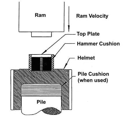
Upon impact with the pile accessory, the ram creates a force far larger than its weight, which, if sufficiently large, then moves the pile an increment of penetration into the ground. The mass falls a certain distance called the stroke. If the stroke is too low, the pile will not move into the ground. If the stroke is too high, the pile may be damaged. The stroke of a pile-driving hammer is usually between three and ten feet (900 to 3000 mm).
A properly functioning hammer strikes the pile in quick succession. It transfers a large portion of the kinetic energy of the ram into the pile.
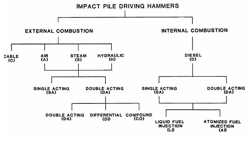
3.2.1. External Combustion Hammers
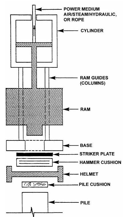
External combustion hammers are hammers that burn the fuel that provides the energy for the operation of the hammer outside of the hammer itself. These hammers have external power sources such as the crane itself, steam boilers, air compressors, and/or hydraulic power packs to provide the energy to move the ram upward, and in some hammers, downward as well. The various types of external combustion hammers are detailed below. Figure 3-4 shows the basic components of an external combustion hammer.
3.2.1.1. Drop Hammers
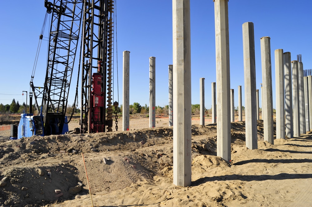
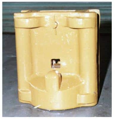
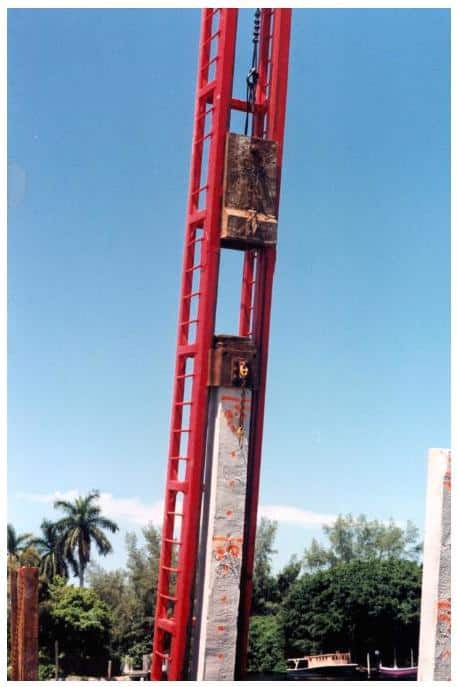
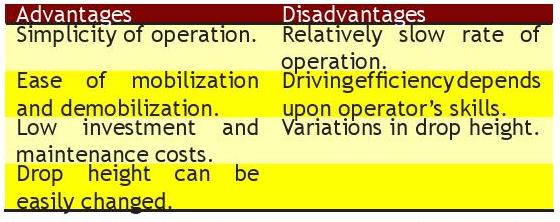
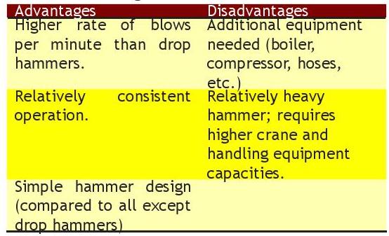
The drop hammer is the oldest type of pile driving hammer in existence. A typical drop hammer is shown in Figure 3-5. The hammer is connected to a cable that is attached to a winch on the crane. The hammer is raised to the desired stroke. The winch has a clutch on it that then allows the operator to release the hammer, which falls by its own weight and strikes a pile cap and the pile. A hoist from the same crane, which supports the pile and the leads, usually lifts it. After lifting the ram to the desired stroke, it is dropped by either a tripping mechanism or by releasing the hoisting drum, as shown in Figure 3-6. In the former case, all the developed energy remains in the ram; in the latter case, some energy is needed to unwind the cable from the drum. The available energy per blow of a drop hammer is the product of the ram weight times the drop height. Standard ram weights range from 500 to 10,000 lbs (2.5 to 50 kN). Typical drop heights are approximately 4’ (1.2 m). For a given hammer, varying the drop height can vary the energy per blow. Drop hammers are typically used on very small projects and for small piling. The advantages and disadvantages of drop hammers are shown in Table 3-1. It should be noted that a pile cap and leads should always be part of a driving system to ensure that the ram hits the pile axially, and to protect the pile top from damage.
One variation of the drop hammer currently is one that requires only a minimal amount of headroom. The idea utilizes a pipe pile with a large enough diameter to allow the pile hammer to move up and down inside the pipe’s walls. The hammer impacts onto a “stop” built into the bottom, inside of the pipe pile. As the pile is driven, the impact occurs near the toe of the pile. The pile is actually pulled down into position in lieu of being pushed. This configuration minimizes the need for the additional overhead clearance (leads, crane, etc.).
For drop hammer arrangements that require the ram unwind the cable from the drum during its fall, the effective energy of the hammer is reduced because of the friction loss and the inertia of the drum and the cable assembly. Just before impact, the operator sometimes “catches” the ram, thereby reducing the impact velocity. The operator often does not achieve constant strokes, and variable energy outputs result from to blow. An additional source of energy losses is the friction between the ram and the leads. Going through the checklist that follows can minimize these factors.
3.2.1.1.1. Checklist for Drop Hammer Inspection
3.2.1.1.1.1. Before Driving Begins
• Check ram weight.
• Check material, size, and the condition of the hammer cushion.
• Check the pile cushion (if present), size and condition.
• Check that helmet and pile are well matched.
• Check helmet weight.
• Check straightness of leads and connections of lead parts for tightness.
• Make sure that the portion of the leads that guide the ram, as well as all pulleys used are well greased.
• Clearly mark the leads as a reference for drop height observations.
• Check the alignment between the leads and the pile.
• Make sure that the cable and the drum components are well lubricated.
• Check the condition of the hoisting cable.
3.2.1.1.1.2. During Driving
If a trip mechanism is not used, be certain that the hoisting cable is spooling freely, i.e., that there is no tension in the cable just before and during impact.
• Make sure that the desired hammer stroke is consistently maintained.
• Check that ram, helmet, and pile maintain alignment during driving (no excessive swaying due to the lifting and releasing of the ram).

3.2.1.2. Single Acting Air/Steam Hammers
Single acting air/steam hammers are essentially drop hammers, except that the hoisting cable is replaced by pressurized air or steam (motive fluid). The ram is usually a short, stocky block of steel that is connected at its top to a piston. It is guided by columns or inside guiding enclosures, depending on the particular design1. Vulcan, Conmaco, MKT, Menck, and Raymond manufacture single acting air/steam hammers most commonly encountered in the United States. Vulcan, Raymond and Conmaco have very similar designs. Single acting air/steam units from Vulcan and Menck are commonly used to drive piles offshore. A typical single acting air/steam hammer is shown in Figure 3-7.
The maximum available energy per blow for a single acting air/steam hammer is expressed as the product of ram weight times stroke. Ram weights for current production models are between 3 and 300 kips (14 and 1,500 kN). Strokes vary from 2 to 5 ft (.6 to 1.5 m). Thus, energy ratings may be between 6 and 1,500 kip-ft (10 and 2,250 kNm).
The operating rate of single acting air/steam hammers range between 35 and 60 blows per minute. This rate is comparable to most other hammer types that lack downward assist.
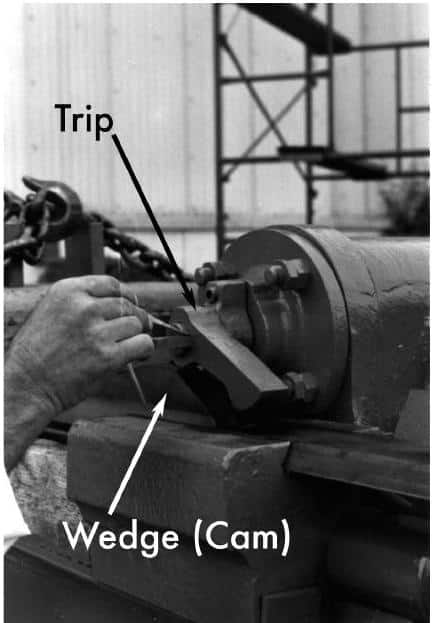
Most single acting air/steam hammers have a fixed stroke. A slide bar with cams (Figure 3-8) is attached to the ram for the tripping of valves on the ram cylinder. However, the stroke of some hammers can be varied if the slide bar is equipped with a dual set of cams and with a valve trip which can be moved to either set of cams. This adjustment is usually done remotely by means of a hydraulic line. The primary advantage of variable stroke hammers is their ability to reduce damaging driving stresses during the early stages of driving when lower soil resistance is encountered.
3.2.1.2.1. Operation
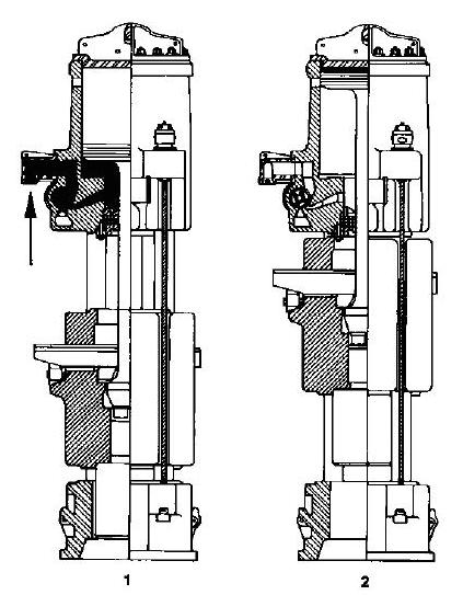
The operating cycle of a single-acting air/steam hammer is shown in Figure 3-10. The hammer operates in a two-step cycle as follows:
1. A blow of an air/steam single-acting hammer is initiated by introducing the motive fluid at constant pressure in a cylinder under the piston. The pressure increases in the cylinder and causes the ram to move upward. At a certain height (usually 50-75% of the maximum fall height), the pressure inlet valve is closed and the pressure chamber is opened to the atmosphere.
2. The ram will coast upwards under its momentum for an additional distance. Towards the top of a full stroke, the piston penetrates a safety chamber formed by trapped air above the so-called relief ports, which assists in the deceleration of the piston. Upon its descent, the ram reaches a position – usually immediately preceding impact – where the valve opens to allow motive fluid to enter the cylinder. The exhaust is closed at the same time.
Obviously, if pressurized motive fluid enters the cylinder too soon before impact occurs, this pressure will tend to slow the fall of the ram. This effect is called pre-admission; it may have a significant effect on the striking velocity. An incorrect hammer cushion thickness, poorly adjusted valves, or an improper slide bar may cause this problem.
During impact, the ram pushes the helmet and pile downwards, allowing the hammer base, columns, and cylinder (these components are also called the assembly) to fall under the action of both gravity and the reaction forces of the pressurized fluid. When the hammer base meets the helmet, a so-called “assembly impact” occurs.
Since the air/steam hammer is an external combustion hammer, its performance depends on the boiler (steam generator) or air compressor. Either unit must be of sufficient capacity to provide the operating pressures at the necessary fluid flow rate. The hammer specifications therefore require an operating pressure and an operating volume (e.g., cubic feet per minute or cubic meters per minute).
The specified pressures must be available at the hammer, and the system losses must be minimized. Pressure losses may result from leaky or worn hoses, or in hoses of insufficient number of size or excessive length.
Single acting air/steam hammers should be used with a pile helmet inserted between the ram and the pile top. The helmet usually supports the hammer assembly, and houses the striker plate and the hammer cushion, if so required by the manufacturer. The helmet must be well matched to both pile type and hammer model. For high hammer cushion stacks (such as those commonly used with micarta and aluminum stacks), a follower or shield may be inserted between hammer and helmet; its effect is to extend the upper portion of the helmet. Such a follower or shield should only be used after obtaining approval from the engineer.
A correct cushion thickness is important for the proper performance of a hammer. Thinner than specified cushions may cause pre-admission, which cushions the blow. A taller cushion stack than recommended shortens the ram stroke. The shorter stroke will, of course, produce blows with lower energy. If the cushion thickness increases even further, then the inlet valve may not open at all, and the hammer will not run. It is very important to start with and maintain a hammer cushion thickness as specified by each manufacturer for each hammer model.
3.2.1.2.2. Checklist for Single Acting Air/Steam Hammers
3.2.1.2.2.1. Before Driving Begins
• Check hammer model and serial number to ensure that the hammer has the proper energy rating.
• Check material, size, and the condition of the hammer cushion. When measuring the hammer cushion thickness, the thickness of the striker plate should also be measured and then added.
• Check the pile cushion (if present) for size and condition.
• Check that the helmet and pile are well matched.
• Check helmet weight; if in doubt have it weighed.
• Check straightness of leads and connections of lead parts for tightness.
• Make sure that the portions of the leads that guide the hammer do not offer excessive friction.
• Check the alignment between the leads and the pile.
• Mark ram guides or check hammer for reference points as a reference for stroke observations.
• Check number, size, and length of steam or air hoses.
• Make sure that hoses are cleared of obstructions before they are connected to the hammer.
• Check that the motive fluid lubricator is filled with an appropriate lubricant.
• Inspect the slide bar and its cams for excessive wear.
• Check the columns (ram guides), piston rod and slide bar are well lubricated.
• Make sure that the ram keys and column keys are all tight.
3.2.1.2.2.2. During Driving:
• Make sure that the desired hammer stroke is maintained.
• Check that the ram, helmet, and pile maintain alignment during driving.
• Check that pressure at compressor or boiler is equal to the rated pressure plus hose losses. Pressure should not vary significantly during driving.
• Measure the rate of hammer operation in blows per minute. A stopwatch may accomplish this.
• Make sure that the motive fluid is well lubricated. After a short period of pile driving, lubricant should drip out of ports.
• Continuously check the quality of the motive fluid; condensation or icing of air, and water in steam are all signs of a motive fluid in a poor condition.
• Check that the hammer hoist line is always slack.
• Record when hammer or pile cushioning material is replaced or added to the driving system. New cushion material should not be added towards the end of driving; a minimum of 100 blows should be applied before final blow counts for capacity determination are taken.
3.2.1.3. Double, Differential and Compound Acting Air/Steam Hammers
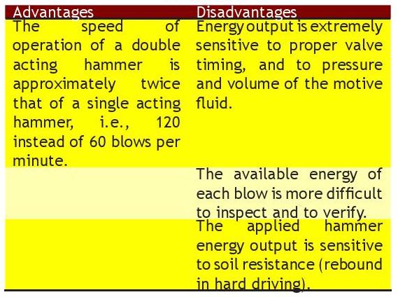
The desire to create a hammer that applies blows in rather quick succession for increased productivity led to the development of double acting air/steam hammers. For an increase in blow rate, the stroke was shortened, and in order to maintain a comparable energy rating, the ram was accelerated during its down stroke by means of active pressure. Advantages and disadvantages of these hammers are shown in Table 3-3.
-
 SPW911 Sheet Pile Design Software
Rated 5.00 out of 5$150.00 – $599.99Price range: $150.00 through $599.99
 -
 Sheet Pile Design (PDF Download)
Rated 5.00 out of 5$89.00
 -
 Pile Driving (PDF Download)
$89.00
-
 Marine Construction Volumes 1 & 2 (PDF Download)
$157.00
-
 Pile Driving (Book)
$89.00


