Chapter 1 – Pile Driving Introduction
For a complete version of this document click here.
1.1. History
Piles are braced, structural columns that are driven, pushed or otherwise installed into the ground. Pre-literate man found that pile foundations were very useful in that they allowed construction of a shelter high above the water or the land and out of reach of marauding animals and warring neighbors. Driven piles are the oldest type of deep foundation in existence. They enable the placement of structures in areas that are otherwise unsuitable because of the subsurface condition.
Pile driving is the process of installing a pile into the ground without previous excavation. Historically, the oldest method of driving a pile, and the method most often used today, is by a hammer. No doubt, the earliest bearing piles were driven by hand using a wooden mallet of some sort.
1.1.1. Pile Driving in the Roman World
Although the Romans were neither the most innovative builders nor the ones with the most impressive single structures, (the Egyptians with the pyramids claim that honor) they were the most accomplished planners of infrastructure in the ancient world. Because of the varied soils they encountered around the Mediterranean Sea, they also drove many piles to support the military and civil works which they undertook.
The Latin word for pile driver is fistuca or festuca, which is defined as follows:
FISTU’CA, an instrument used for ramming down pavements and threshing floors, and the foundations of buildings (Cato, R.R. 18, 28; Plin. H.N. xxxvi.25. s61; Vitruv. iii.3 s4 §1, x.3 s2 §3); and also for driving piles (Caes. B.G. iv.17). When used for the former purpose, that of making earth solid, it was no doubt a mere log of wood (shod perhaps with iron), with handles to lift it up; just like a paviour’s rammer. But in the case cited from Caesar, where it was used for driving the piles of his bridge over the Rhine, it is almost evident that it must have been a machine, something like our pile-driving engine or monkey), by which a heavy log of wood, shod with iron, was lifted up to a considerable height and then let fall on the head of the pile.1
One of the oldest bridges in Rome was the “Pons Sublicius” or “bridge of piles.” In 509 B.C. the Romans expelled their last king and established a republic. The kings took refuge at the court of Lars Porsena, the king of neighboring Clusium; three years later, they attempted to retake the city. They had not prepared to deal with the bridge and its defender, Horatius Cocles:
Once more Horatius stood alone; with defiance in his eyes he confronted the Etruscan chivalry, challenging one after another to single combat, and mocking them all as tyrants’ slaves who, careless of their  own liberty, were coming to destroy the liberty of others. For a while they hung back, until shame at the unequal battle drove them to action, and with a fierce cry they hurled their spears at the solitary figure which barred their way. Horatius caught the missles on his shield and, resolute as ever, straddled the bridge and held his ground. The Etruscans moved forward, and would have thrust him aside by the sheer weight of numbers, but their advance was suddenly checked by the crash of the falling bridge and the simultaneous shout of triumph from the Roman soldiers who had done their work in time. The Etruscans could only stare in bewilderment as Horatius, with a prayer to Father Tiber to bless him and his sword, plunged fully armed in the water and swam, through the missiles which fell thick about him, safety to the other side where his friends were waiting to receive him.2
At the end of the Roman Republic, we have what is probably the most spectacular documented application of piles in the ancient world. This was done by Julius Caesar’s army in crossing the Rhine River during his extended campaign in Gaul. He described the job as follows:
…(Caesar) caused pairs of balks a foot and a half thick, sharpened a little way from the base and measured to suit the depth of the river, to be coupled together at an interval of two feet. These he lowered into the river by means of rafts, and set fast, and drove home by rammers; not, like piles, straight up and down, but leaning forward at a uniform slope, so that they inclined in the direction of the stream. Opposite to these, again, were planted two balks coupled in the same fashion, at a distance of forty feet from base to base of each pair, slanted against the force and onrush of the stream. These pairs of balks had two-foot transoms let into them atop, filling the interval at which they were coupled, and were kept apart by a pair of braces on the outer side at each end. So, as they were held apart and contrariwise clamped together, the stability of the structure was so great and its character such that, the greater the force and thrust of the water, the tighter were the balks held in lock. These trestles were interconnected by timber laid over at right angles, and floored with long poles and wattlework. And further, piles were driven in aslant on the side facing downstream, thrust out below like a buttress and close joined with the whole structure, so as to take the force of the stream; and others likewise at a little distance above the bridge, so that if trunks of trees, or vessels, were launched by the natives to break down the structure, these fenders might lessen the force of such shocks, and prevent them from damaging the bridge.3
1.1.2. Other Pile Driving before the Nineteenth Century
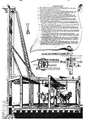
Piles in the Roman world were exclusively wood piles; this was to remain the case for all piling until the end of the nineteenth century. These wood piles were driven by drop hammers on small wooden rigs. A variety of these rigs is shown in Figure 1-1. A more elaborate rig of this type from the eighteenth century is shown in Figure 1-2.
 For thousands of years the Chinese and other oriental builders used a stone block as a hammer. It was lifted by ropes and stretched taut by human beings, who were arranged in a star pattern about the pile head. The rhythmic pulling and stretching of the ropes flipped the stone block up and guided the downward blow upon the pile head.
The City of Venice was built in the marsh delta of the Po River because the early Italians wanted to live in safety from the warring Huns of Central Europe. The buildings of Venice are supported on timber piles, driven centuries ago through the soft mud onto a layer of boulders below. When the bell tower of St. Mark’s, built in 900 A.D., fell in 1902, the timber piles in the foundation were found to be in such a good state of preservation that they were used to support the reconstructed tower.
1.1.3. Advances in the Nineteenth Century
The nineteenth century saw real progress on several fronts for driven piles. To begin with, steam replaced muscle power for the turning of the winches. Other developments at that time include the steam hammer, concrete piles and the first dynamic pile driving formula.
1.1.3.1.Naysmith’s Steam Hammer
Drop hammers had served civilization well for centuries; however, they are slow and require some skill from the operator in use. The development of the steam engine in the eighteenth century in both Britain and Russia showed the potential of steam power. The Scottish inventor James Naysmith developed the first steam hammer. In 1839 he sketched out the first design of the steam hammer; he described it as follows:
My Steam Hammer as thus first sketched, consisted of, first, a massive anvil on which to rest the work; second, a block of iron constituting the hammer or blow-giving portion; and, third, an inverted steam cylinder to whose piston-rod the hammer-block was attached. All that was then required to produce a most effective hammer was simply to admit steam of sufficient pressure into the cylinder, so as to act on the under-side of the piston, and thus to raise the hammer-block attached to the end of the piston rod. By a very simple arrangement of a slide valve, under the control of all attendant, the steam was allowed to escape and thus permit the massive block of iron rapidly to descend by its own gravity upon the work then upon the anvil.
Thus, by the more or less rapid manner in which the attendant allowed the steam to enter or escape from the cylinder, any required number or any intensity of blows could be delivered. Their succession might be modified in an instant. The hammer might be arrested and suspended according to the requirements of the work. The workman might thus, as it were, think in blows. He might deal them out on to the ponderous glowing mass, and mould or knead it into the desired form as if it were a lump of clay; or pat it with gentle taps according to his will, or at the desire of the forgeman.4
This hammer was originally intended as a forge hammer for steel production. In 1845, however, Naysmith designed and built a steam hammer for driving piles at the Royal dockyards at Devonport, England.
He describes this first job as follows:
Some preliminary pile-driving had been done in the usual way, in order to make a stage or elevated way for my pile-driver to travel along the space where the permanent piles were to be driven. I arranged my machines so that they might travel by their own locomotive powers along the whole length of the coffer dam, and also that they should hoist up the great logs of Baltic timber which formed the Piles into their proper places before being driven. The entire apparatus of the machine was erected on a strong timber platform, and was placed on wheels, so that it might move along the rails laid down upon the timber way. The same boiler that supplied the steam hammer part of the apparatus served to work the small steam-engine fixed to the platform for its locomotion, and also to perform the duty of rearing the next pile which had to be driven. The steam was conveyed to the hammer cylinder by the jointed pipe seen in the annexed engraving. The pipe accommodated itself to any elevation or descent of the hammer. The whole weight of the cylinder, hammer-block, and guide box, supported by the shoulders of the pile, amounting to seven tons in all, rested upon the shoulders of the pile as a “persuader;” and the eighty blows per minute of the four-ton hammer came down with tremendous energy upon the top of the pile head. No soil, that piles could penetrate, could resist such effective agencies…There was a great deal of curiosity in the dockyard as to the action of the new machine. The pile-driving machine-men gave me a good-natured challenge to vie with them in driving down a pile. They adopted the old method, while I adopted the new one. The resident managers sought out two great pile logs of equal size and length–70 feet long and 18 inches square. At a given signal we started together. I let in the steam, and the hammer at once began to work. The four-ton block showered down blows at the rate of eighty a minute; and in the course of four and a half minutes my pile was driven down to the required depth. The men working at the ordinary machine had only begun to drive. It took them upwards of twelve hours to complete the driving of their pile!

In the U.S., steam hammers came into use after 1875. After manufacturing other designs, Vulcan Iron Works developed in 1887 the first “#1” hammer designed by the Warrington brothers, George, James N. and William H. This hammer (and its derivatives, the Raymond and Conmaco hammers) became the most popular steam hammers in the U.S. The McKiernan Terry Corporation (MKT) also developed a successful line of steam hammers, along with the Union and Industrial Brownhoist hammers. In Europe steam hammers were developed by such manufacturers as BSP (U.K), Menck + Hambrock (Germany), and Nilens (Belgium).
The original steam hammers were single acting, i.e., they relied solely on the drop of the ram through the gravity field for the kinetic energy used to drive the pile. The twentieth century saw the development of hammers with downward assist of some kind, where the steam (and later the compressed air) was used to accelerate the ram downward more than gravity. These fell into two types. The first were the compound hammers, which used the air or steam expansively on the downstroke. They included first the Vulcan “California” series hammers and later the MKT “C” series hammers. The second were the double or differential acting hammers, which simply used the air or steam at full pressure to help accelerate the ram downward. Vulcan developed the differential acting hammer in the 1930’s in both closed and open type; Raymond developed its own differential acting hammers, first steam and then hydraulic. MKT’s successful double-acting “B” series is still commonly used to drive sheet piling. European manufacturers also developed closed-type double acting hammers.
1.1.3.2. Raymond’s Concrete Piles
Under the proper conditions, timber piles are a very durable pile type, but timber piles are subject to varying degrees of deterioration. Moreover, timber piles are limited in length and size by the trees they come from.
The French engineer François Hennebique was one of Europe’s premier bridge builders. In 1897, he introduced the use of reinforced concrete piles. The U.S. was not far behind and in 1901, A.A. Raymond first used concrete piles in a building foundation in Chicago. Raymond went on to found the Raymond Concrete Pile Company, which for most of the twentieth century was the greatest pile driving organization in the world, even extending its activities to the construction of offshore oil platforms with steel pipe piles.
Timber piles were usually driven to less than 50 kips (222 kN) allowable capacity, but the new concrete piles were designed for 60 kips (267 kN) and higher. This meant that fewer piles and smaller footings could be utilized for the same imposed loads. Technological advances in the cement and concrete industries made concrete piles cost competitive and, because of this, their use became prevalent.
1.1.4. Steel Piles
The beginning of the twentieth century also saw the start of the use of steel piling as well, both H-piles and pipe. Both of these steel shapes existed for structural use and were adapted to piles. In the case of pipe, though, the evolution of tubular steel piling went in two distinct directions:
• Without concrete fill, as open ended or closed ended pipe piles: These are typically used in applications where lateral or tensile loads predominate, such as offshore oil platforms and seismic or scour resisting members.
• With concrete fill: This includes a wide variety of piles, such as caissons, bulb piles, Monotube piles and (when the steel is thin enough) shell piles driven with mandrels, such as the Raymond Step-Taper® piles.
H-piles were an outgrowth of I-beams driven to meet a serious problem: scour undermining of bridge piers and abutments in compact sand and gravel. The piles could withstand both hard driving and were able to be driven deep enough to adequately resist scour. Bethlehem Steel rolled the first H-pile in 1908 and this replaced the I-beams used before that time.6
1.1.5. Advances in Rigs
No history of piling would be complete without some mention of the advances in pile driving rigs.
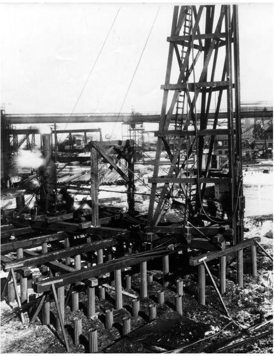
The most popular type of pile driving rig before the advent of crane-mounted rigs was the skid rig, as shown in Figure 1-4. Skid rigs dominated the industry in an era when the motto was frequently “when in doubt, drive piles.”
An advance with the skid rig is the rotating rig. Raymond built its first rotating rig in 1913 and continued to build them until 1929 and use them into the 1950’s. They consisted of a bedsill with a 12’ (3.66 m) rail circle and a turntable with a 13’-8” (4.17 m) fixed radius from kingpin to the centerline of the turntable. The leaders were mounted on the front of the turntable, were of rugged construction and were 56’ (17 m) in height. A larger and heavier version of this was the Long Swing Driver.
The advent of large mobile cranes, with their greater maneuverability, led to a new era in pile driving rigs.
1.1.6. Pile Dynamics
Pile driving is an “interdisciplinary” process in that it is a combination of geotechnical engineering (the interaction with the soils), engineering mechanics (the dynamics of moving bodies) and structural engineering (the stresses during driving and after installation.) Nowhere is that better illustrated than in the subject of pile dynamics.
1.1.6.1. Dynamic Formulae
The first attempt to model the dynamics of pile driving and to make this modeling useful to practitioners were the dynamic formulae. These formulae use Newtonian impact mechanics to model the motion of the pile; these results could generally be expressed in a simple formula, which could be readily applied to the work at hand.
The most widely used dynamic formula is the Engineering News formula, although many others (and their local variations) have made their way into codes and other standards of practice (Hiley, Gates, Danish, etc.) Many foundations have been installed using these formulae as a basis of pile control and acceptance.
The dynamic formulae have been pilloried extensively since the wave equation became practical to use. Their three main weaknesses are
• Modeling of the pile as one rigid mass;
• Inadequate modeling of the driving system (hammer, cushion, helmet);
• Inadequate modeling of the soil as it interacts with the pile.
These weaknesses and others were not as apparent when timber piles installed using drop hammers was the norm in pile driving. With the introduction of concrete and steel piles these deficiencies became critical, especially when concrete piles began to exhibit tension cracking, a phenomenon the dynamic formulae could neither anticipate nor quantify.
1.1.6.2. Application of Stress-Wave Theory to Piles
It seems difficult to believe that such a simple looking operation as pile driving can involve such a complicated phenomenon as stress-wave propagation. The history of the theory’s application, however, is important in the continued viability of driven piles as a deep foundation. The theory is discussed later in this book; the following is an overview of the development of this theory with application to piles.
1.1.6.2.1. Isaacs’ Work
The use of the wave equation (or stress-wave theory) to model impact pile driving began in Australia with the work of David Victor Isaacs. The dynamic formulae had been developed primarily with timber piles in mind; with the growing usage of concrete piles, it became apparent that, because of the length and properties of timber piles, the dynamic formulae (with their assumption that the pile is a rigid mass) would not be sufficient for concrete piles. Isaacs began by reviewing the dynamic formulae. Part of his review included a discussion of the factor of safety, where he makes a statement that is still relevant:
It should be remembered, however, that these are not true factors of safety, but include a “factor of ignorance.” The author suggests that when the ultimate resistance of any pile has been determined, in fixing the factor of safety…the most unfavourable conditions possible in the supporting strata should be judged (the range of conditions possible being narrowed with better knowledge of the subsurface conditions and of the possibility of disturbance from extraneous sources) and a proportion of the factor of safety — a “factor of ignorance” — then allowed in respect to these possible conditions, the manner of determining the ultimate load, and the type of loading to be borne. The remaining proportion of the factor of safety — or true margin of safety — should be approximately constant for all classes of loading and foundation conditions involving the same value of loss in case of failure; and the overall factor of safety…will then be equal to the product of the true factor of safety with the “factor of ignorance.”
He also describes an experiment where rods are impacted against each other in a pendulum arrangement. As the rods were lengthened, the behavior of the rods deviated more and more from Newtonian impact theory.
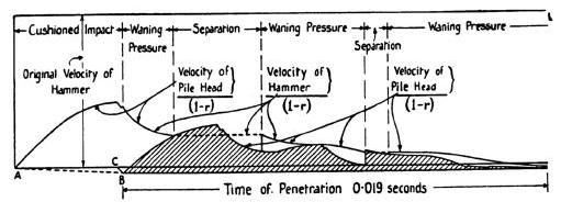
He then developed an integration technique that is best described as a semi-graphical one. He developed a mathematical model based on the successive transmission and reflection of waves (similar in principle to the method of images.) A sample solution is given Figure 1-7, in this case showing multiple impacts.
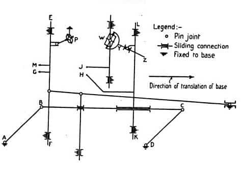
He then constructed a machine to graphically integrate the solution, a diagram of which is shown in Figure 1-8.
He was then able to solve for the stresses and displacements of the pile during driving. Isaacs developed a set of formulae and charts to make his results accessible for the analysis of piles.
In the course of the investigation, Isaacs dealt with a number of questions that would become central to stress wave analysis of piles, including tension stresses in concrete piles, the effect of ram weight (he concluded that a heavier ram reduced tension stresses,) and the effect of hammer cushion stiffness and drive cap weight.
Isaacs’ work also revealed the computational complexity of stress wave analysis, a complexity that insured the dominance of dynamic formulae in pile analysis (with all of their serious limitations) for another half century.
1.1.6.2.2. The Work of Glanville
After Isaacs’ work, the centre of work on the subject shifted to the United Kingdom, with the extensive study commissioned by the British Building Research Board under the direction of (later Sir) W.H. Glanville and his colleagues. This study was one of the first comprehensive studies on stress waves in piles. It was commissioned in part to investigate problems encountered in the breakage of concrete piles during driving, at both the head and the toe. The wave equation using d’Alembert’s solution were used to develop equations to estimate the stress in the pile during driving, using the method of images. Because of the complexity of the equations, the results were reduced to a series of charts where a quantity of dimensionless stress was plotted against the ratio of hammer weight to pile weight. The charts could then be used to estimate pile stresses and resistance. The charts were applicable to concrete piles only, and this was a serious limitation to such solutions.
 In addition to developing a solution to the wave equation, the authors continued Isaacs’ work in addressing technical issues and experimental techniques that have enduring interest in pile dynamics. These include the instrumentation and data collection on stresses and forces in piles, including remote data gathering through “portable” equipment in a trailer, further research on the effect of the hammer cushion on the generation and effect of the pile stress wave (these were included in the analytical work,) drop tower testing on cushion material to determine the cushion stiffness, and further work on the relationship of ram weight to pile weight and cross section. An example of the data collected is illustrated in Figure 1-9, which shows actual photographs of the oscilloscope readings recording stresses at various points of the pile during driving. Note that the stress wave impulse at the middle is delayed from the head, as is the “foot” from the middle; this is as predicted by stress wave theory.
The Second World War interrupted further research; moreover, the difficulties that this study encountered in developing a readily usable prediction technique ended the possibility of using a closed form solution for this application. Research has continued to the present on closed form solutions9.
1.1.6.2.3. Enter the Numerical Methods
The difficulties in applying the closed form solutions, led to the use of numerical methods to model stress waves in piles and pile behavior itself. Today we say “obvious” but in the 1940’s and 1950’s, this was not the case, primarily because the practical application of numerical methods required the use of the recently developed digital computer. Moreover geotechnical engineering in general was slower than other specialties to adopt advanced analytical techniques, primarily because the ground itself presented complexities that are in reality only now beginning to be modeled on a reasonable basis. Experience and judgment, essential elements in any engineering practice, were and are especially important in geotechnical applications.
This background clearly illustrates how remarkable the accomplishment of E.A.L. Smith10 really is. Smith was the Chief Mechanical Engineer for the Raymond Concrete Pile Company. By the time his historic “wave equation” paper had been published, he had already retired. The basic elements of Smith’s technique are as follows:
• Division of the pile into a series of springs and masses. The hammer was modeled as a mass with a hammer cushion spring (or capblock, to use the Raymond terminology.) The driving accessory (or follower) was also modeled as a mass, with provision for another cushion for the pile if needed.
• Integration of the model using a first order finite difference technique.
• Modeling of the hammer and pile cushions using a “static” hysteresis technique, defined by an elastic spring constant during compression and modified by a “coefficient of restitution” during rebound.
• Modeling of the soil as a combination of displacement dependent springs and velocity dependent dampers. These were applied both along the pile shaft and at the pile toe as the actual soil resistance distribution required.
• Modeling of the non-linearities of the soil. The soil was given a “yield limit” (a quake); after this deflection the non-dynamic resistance was constant. The model could simulate yielding in some areas of the pile without requiring it in others.
Smith made many of the assumptions for his model (especially for the soils) with a minimum of theoretical basis; nevertheless, the soil model he proposed is still standard in many wave equation programs today. This is a tribute to the durability and basic soundness of his technique.
In spite of the advanced state of Smith’s model, it was several years before it was disseminated to practitioners. The first version of Smith’s model that was made available to a wider audience was the TTI (Texas Transportation Institute) program, developed at Texas A&M University by L.L. Lowery and T.J. Hirsch11. In addition to making Smith’s model available, many of the assumptions behind the Smith model were examined to improve the quality of the input and thus confidence in the output. The TTI program is still available and is used especially with offshore oil and gas platform piling.
When Smith developed his wave equation method, he only included hammers whose rams could be modeled as rigid, impacting a hammer cushion. This is principally because Raymond used steam hammers at the time. Both the Smith had the TTI programs had only a rudimentary modeling of the combustion complexities of diesel hammers, which became popular in the U.S. in the 1960’s. This deficiency was overcome with the WEAP program, developed by George Goble and Frank Rausche12. In addition to advancing the modeling of the diesel hammers, WEAP and its successors gave the wave equation for piling the one thing it needed more than anything else: an organization (GRL) prepared to actualize it through support and dissemination. An example of this technical support was WEAP86, WEAP87 and GRLWEAP, which include a hammer database and PC capability. The need for technical support became more critical with the development of pile monitoring techniques in the field.
There are other wave equation computer codes in use today, such as TNOWAVE, by TNO in the Netherlands. In addition to the finite difference technique, there have been finite-element methods used, either one-dimensional or with the surrounding soil modeled13.
1.1.6.3 Field Monitoring Techniques
Geotechnical engineering principles are inherently influenced by the high degree of uncertainty created by the use of soil and rock as an engineering material. The wide variability of soils and the difficulty inherent in modeling their behavior makes some kind of in situ verification essential.
With driven piles, dynamic formulae gave the industry just such verification. By relating the blow count of the hammer per foot (or inch, meter, etc.) of pile penetration to the resistance of the pile, the capacity of piles could be estimated. This unusual situation made the pile hammer both an installation tool and a measuring device.
Although the wave equation enabled prediction of performance, relating that prediction to the actual capacity or resistance of the pile involves more than just comparing the wave equation to the static load test. From the beginning, the need for pile installation instrumentation was felt necessary to learn more about the pile’s behavior both during driving and when loaded by the structure.
The first comprehensive (and successful) attempt at instrumentation was Glanville’s study. Subsequent efforts in this direction took place in Sweden, at the Gubbero site in 196014. Both of these efforts relied on the photographed output of an oscilloscope.
The major step in using stress wave theory to analyze piles during driving and to estimate their static capacity was the development of the Case Method15. This method compared the pile force and velocity at a given time with a time 2L/c after that. The static and dynamic soil resistance components were then separated. This method was very simple and could be readily applied in the field, through the measurement of force and acceleration near the pile head using both strain gages and accelerometers.
A more advanced analytical computer model of the measured data became available with CAPWAP16 (Case Pile Wave Analysis Program). This technique uses similar instrumentation to the Case Method, but allows further refinement of the soil response through in iterative technique. A profile of the soil resistance distribution is thus obtained along with end bearing resistance.
Other organizations (such as TNO) have developed methods of analyzing the return signals of impact. The result in all cases is once again the use of the hammer, this time in conjunction with stress wave theory and modern measuring techniques, as a measuring tool to estimate the pile’s capacity as it is being driven.
One further application of stress wave theory in the field is integrity testing. It is used to find the presence of cracks (driven piles) or voids (drilled shafts and auger-cast piles.) There are two variations to this technique:
• Low strain integrity testing, where a small hammer transmits a stress wave along the pile length and the returning echo is analyzed, much like sonar; and
• High strain integrity testing, which is also used to dynamically measure the pile capacity.
1.1.7. Diesel Hammers
Diesel hammers were first developed in Germany in the 1920’s. Their two key advantages were that a) they were able to operate without an external power source and b) they tended to be lighter for a comparable striking energy. They were introduced into the U.S. after World War II, first by the Syntron/Link Belt series of closed ended diesel hammers and then the Delmag diesel hammers from Germany. Today they are manufactured by several manufacturers in various parts of the world.
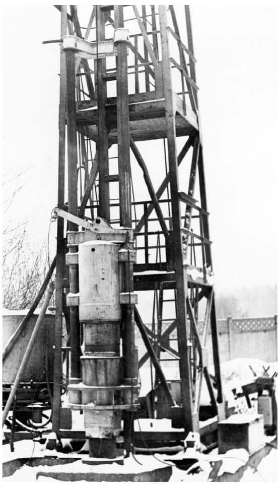
Most diesel hammers manufactured today—and all of these depicted in Chapter 3—are of the tubular, air cooled type. Two variations from these are a) rod type diesel hammers and b) water cooled diesel hammers. Rod type diesel hammer have a ram that runs on columns in a similar manner as air/steam hammers. The combustion chamber is hidden as the air is compressed and the fuel injected and exposed as the ram is thrown upward by the results of the combustion. Rod type diesel hammers are generally restricted today to very small diesel hammers. An example of a rod type diesel hammer is shown in Figure 1-10.
Water cooled diesel hammers have a water tank or jacket surrounding the combustion chamber. These afford superior cooling capabilities, but their inconvenience to the user has limited their popularity.
1.1.8. Vibratory Hammers
The first vibratory pile driver used was in the former Soviet Union, a model BT-5 developed and first used under the direction of D.D. Barkan. This hammer had a dynamic force of 214 kN and the eccentrics rotated at 41.67 Hz, powered with a 28 kW electric motor. Used in the construction of the Gorki (now called once again Nizhni-Novgorod) hydroelectric development. This hammer drove 3700 sheet piles 9-12 m long in 2-3 minutes each.
The Soviets then developed a large variety of vibratory pile drivers and soil drilling equipment in the 1950’s and afterwards. Although space does not permit a complete catalogue of these machines, two are mentioned here as they are of special interest.
• VPM-170. This hammer had a dynamic force
of 1700 kN and the eccentrics rotated at 550 RPM; it was the largest vibratory pile driver the Soviets produced. This was designed to drive pipe piles 1600 mm in diameter into any type of soil except for rocky soils. It could operate at two different frequencies. This hammer is shown in Chapter 3.
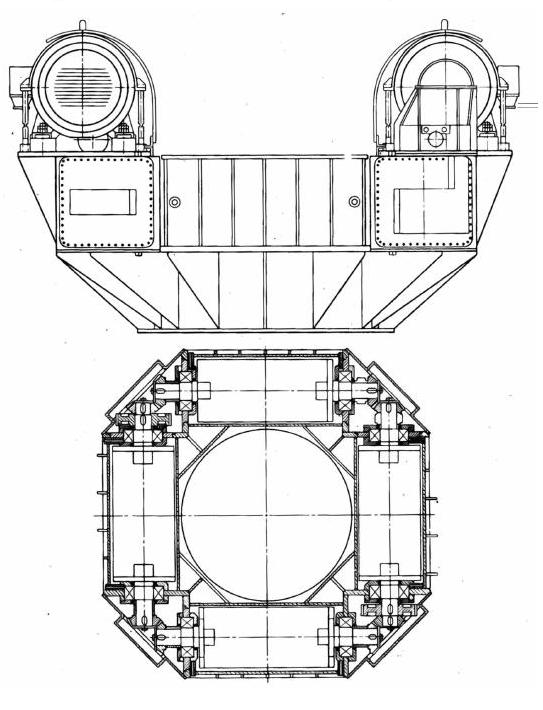
• VU-1.6. It had a dynamic force of 958 kN and the eccentrics rotated at 495 RPM. Like the VPM-170, it was designed to drive pipe piles 1600 mm in diameter, in its case to depths up to 30 m; however, it also could remove the plug from the pile during driving. The machine had a large centre hole 1400 mm in diameter, so that the soil could be removed without having to stop and remove the pile driver. The eccentrics were arranged in a square pattern and synchronized by special gearing on the ends of the shafts. This machine is shown in Figure 1-12.17
The Soviets first licensed their technology to the Japanese, who developed an extensive array of vibratory hammers. Many of the Japanese hammers were not much different from the Soviet ones. One exception was the Uraga hammer; this hammer was unique in that an electric motor was placed inside of each eccentric, thus making it a very “directly driven” machine. This technology has since spread worldwide, with such concerns as PTC and Tramac in France, Müeller, Tünkers and MGF in Germany, Tomen in Japan and ICE Europe in the Netherlands being well established in the field.
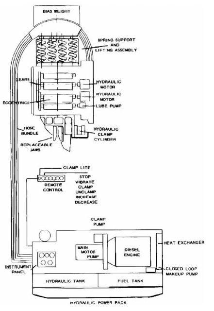
The first American made hydraulic vibratory was the MKT V-10, which they introduced in 1969, although both Vulcan and Foster had introduced Japanese and French vibratory pile drivers respectively in the early 1960’s. A diagram of this machine is shown in Figure 1-13. This pioneering machine differs from most current vibratory pile driving equipment in several respects. In common with the practice of the time, the V-10 suspension used steel coil springs to provide dampening for the crane boom and hook, whereas now most machines use rubber springs. The V-10’s eccentrics were long (a practice borrowed from vibratory screens and separators) and mounted crossways on the machine. A motor was coupled to one of the eccentrics gears transmitted the power to the rest. Most machines today mount the eccentrics from front to back of the case, and drive them either directly or through a speed changing pinion gear.
From this beginning, the unique practices in the U.S. have lead to the evolution of a distinctive style of vibratory hammer in the U.S., and this has
been followed elsewhere. Today it is embodied to a greater or lesser degree in the APE, ICE (America and Europe), MKT, and HPSI units that are on the market. In addition to the changes mentioned above, these characteristics include slim throat hammers for sheet pile driving, hydraulic drive, and high power motors, pumps, and engines.
Classifying vibratory pile driving equipment can be a complex business, but the most important division can be made based on frequency, with the resultant relationships between dynamic force and eccentric moment.
1.1.9. Impact-Vibration Hammers
The term “impact-vibration hammer” refers to a type of vibratory pile driver that imparts both vibrations and impacts to the pile during operation. Based on theoretical work done during the Second World War, S.A. Tsaplin built the first experimental impact-vibration hammer in the Soviet Union in 1949. The specifications of the hammer and test set-up are shown in Table 1-1. In field tests his impact-vibration hammer was welded to the top of metallic tube 110 mm in diameter, 8 mm wall thickness, 2.6 m long and with a mass of 200 kg. The hammer then drove the tube into a variety of sandy, sandy loam, and clay soils. A comparison was made of the effect of driving by the impact-vibration mode versus the vibration mode, the latter of which was achieved by the complete blocking of the springs. The tests made it possible to establish that the efficiency of the impact-vibration driving is substantially higher with regard to both the maximum driving depth and the pile installation speed. It also demonstrated that the efficiency of the driving increases with increasing amplitude of the vibration exciter vibrations.
-
 SPW911 Sheet Pile Design Software
Rated 5.00 out of 5$150.00 – $599.99Price range: $150.00 through $599.99
 -
 Sheet Pile Design (PDF Download)
Rated 5.00 out of 5$89.00
 -
 Pile Driving (PDF Download)
$89.00
-
 Marine Construction Volumes 1 & 2 (PDF Download)
$157.00
-
 Pile Driving (Book)
$89.00


