Geotechnical Analysis and Investigation for Structures
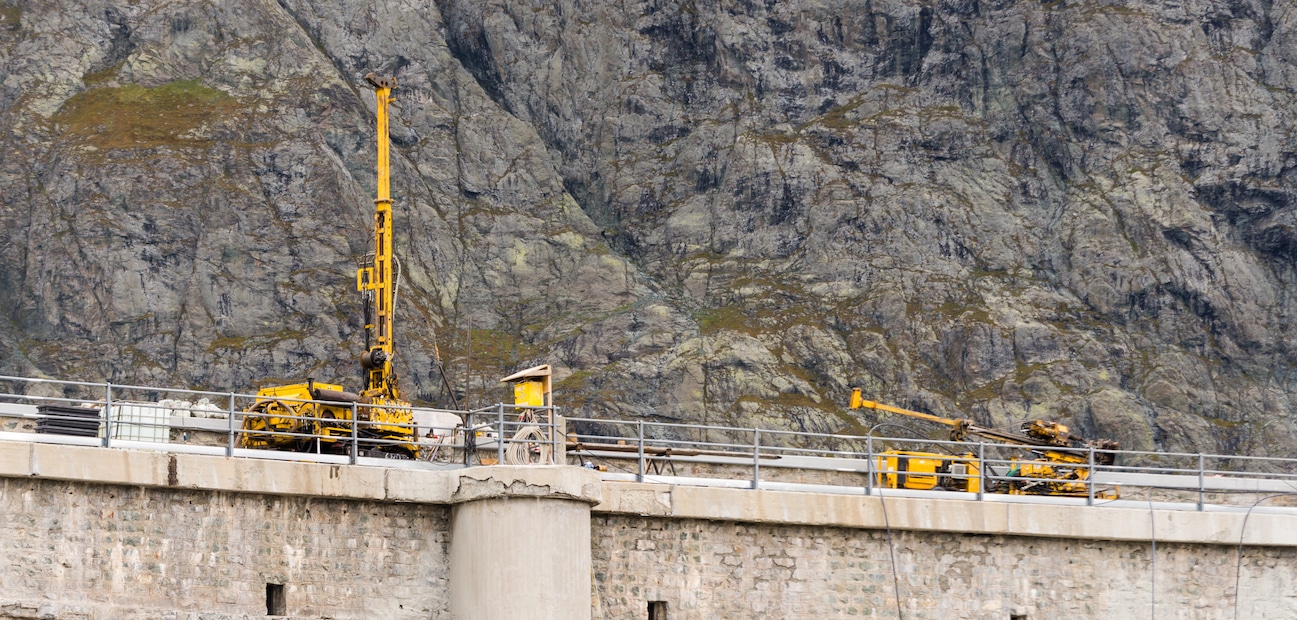

In order to ensure proper support for bridges and other associated structures, it is generally necessary for contractors and other construction managers to engage a geotechnical engineer to make a complete foundation investigation of the proposed foundation. The requirements of such an investigation will vary by state, but will typically contain several key requirements. Having a properly-performed geotechnical investigation and analysis is critical to make sure that bridges and other structures and adequately designed and constructed. Understanding how this process works can help a general contractor or construction company maintain better control over the process and stay on track with their projects.
Planning a Boring Program
The primary method of analyzing the foundation is through sampling the soil and foundation through boring. To plan a boring program, a geotechnical engineer should make use of a number of reference materials, such as water well records and reports, soils an geologic maps, publics and aerial photographs. Based on this research, borings can then be selectively located during a field check, with the location, spacing and depth of borings decided by the topography, geologic conditions, visible soil conditions and design considerations of the project.
Once boring locations have been selected, the borings should be made to a sufficient depth so that the potential for settlement is determined. If deeper excavations for the project are required, then the boring should be carried to at least 1.5 times the depth of the excavation to locate and determine groundwater levels in any aquifers that may exist; if any are found, a dewatering system can be designed prior to construction. The number of borings will often be determined on the initial findings. If soil conditions are favorable and consistent with the first round of borings, additional borings may be unnecessary. If soil conditions are inconsistent across the project site, additional explorations will likely be necessary. Ultimately, the number of borings will be based on the requirements of the structure.
Boring samples should be taken with split-spoon sampling, taken at two-and-one-half-foot intervals for the upper ten feet, and five foot intervals thereafter. Two jar samples from each spoon should be taken to the laboratory for examination and/or testing, with the jars being sealed as soon as possible to avoid moisture loss. After groundwater levels have been measured over a period of 24 hours and the boring program has been completed, the boring holes should be covered to prevent injury to people, animals or equipment.

Methods of Boring
There are a variety of boring methods that can be utilized by geotechnical engineers to obtain soil samples for foundation analysis. The chosen method will depend on a variety of considerations, including the type of project, the soil involved, and the project’s budget.
For certain boring holes, casing may be required. The process of casing involves furnishing and installing driven casing or hollow-stem auger through air, water, soil, shale or watered rock for the purpose of obtaining Shelby tubes, rock cores, or installing field instrumentation.
Hand boring involves using a hand auger (minimum 1-1/2 inch diameter), 1 inch retraction piston sampler, peat sampler, 3 inch minimum post-hole type auger, or a hand guide power auger to obtain samples. When using hand augers, advancing should not exceed six inches.
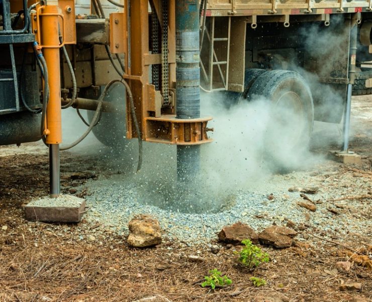
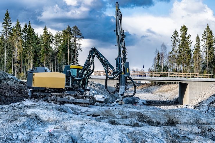
There are two different methods of truck drilling to achieve boring: truck-mounted boring with split spoon sampling and truck-mounted rock-core borings. For split-spoon sampling, a truck-mounted drill rig advances a hole of sufficient diameter to take two inch split-spoon samples and make standard penetration tests, with the possibility of taking three inch-O.D. Shelby tubes and 2-1/8 inch diameter rock cores. Precautions to prevent a free-falling hammer should be taken, such as a minimum of two wraps of rope around the cathead. For rock-core borings, a truck-mounted drill rig with standard diamond core bits and series X or M double-tube core barrels are used to obtain 2-1/8 inch diameter rock core borings. These are typically five feet in length.
Skid drilling can be performed using a skid, bulldozer, all-terrain vehicle or other type of vehicle to obtain borings. This type of drilling is typically considered to be a truck drilling, with an alternative vehicle used to get to the field location.
Soundings involves making continuous-flight auger borings with a powered hand auger, a hand auger, a truck-mounter rig, skid-mounted rig, or a barge-mounted rig in order to determine the depth of rock, surgical peat, or unstable soils or waste deposit. Samples do not need to be obtained for soundings. Soundings may also include making borings through the soil to obtain undisturbed samples at a certain depth for which a casing or drilling fluid ir not used to keep the hole open.
Field records of the boring process should be kept to maintain the integrity of the process. All material that is encountered during boring should be examined and visually classified, and a boring log should be prepared. This boring log should detail the following information: project destination and location; the boring number; final location of boring; method of boring; drill rig type and sample; date of boring and weather; ground elevation; numerical thickness and depth of various soil layers (shown by feet below ground surface or by elevation); a complete description of each soil layer; the elevation of free water during the drilling, at completion of drilling and 24 hours later; additional information obtained during boring, sample number and depth of samples taken; percent recovery on split spoon and undisturbed samples; driller; and inspector.
If rock is encountered during the boring process, additional information should be recorded in the boring log, including the thickness and depth of the rock unit; a description of the rock unit; percent recovery and rock quality designation; description of joints, fractures and bedding planes; location of core fracturing; type and size of core barrel and depths where casing is used; descriptions of penetration rate; zones of drilling fluid loss; zones of water gain; and any unusual occurrences, such as change in color of return wash water. Finally, classification of soil and fill or embankment material depth limits should be shown on all boring logs. The accuracy and completeness of the boring logs is necessary to plot the geotechnical profile and to determine pay quantities for demolition and excavation purposes.

Testing of Boring Samples
If samples are taking during the boring process, they should be submitted to a laboratory for analysis as work progresses. Soil strata samples may undergo a variety of tests, starting with a classification test to determine the type of soil present at the construction site.
Classification tests can verify the visual field classification of a soil classification made by a geotechnical engineer. There are five primary types of classification tests that may be performed, based on the agreement between the general contractor and the geotechnical engineer. These may include a sieve analysis, which involves determining the gradation of a sample using a sieve. Next, a hydrometer analysis may be performed if twenty percent or more of the sample passes the No. 200 Sieve, where a specific gravity determination can be made. A liquid limit test determines the boundary between liquid and plastic states of soil. A plastic limit or plasticity index test can be utilized to analyze the plasticity of the soil. If the soil is found to be non-plastic, then the sample will not be put through the liquid limit test. Finally, a shrinkage limit test can be performed to determine how much soil will shrink.
For certain soil samples, additional tests may be performed to determine moisture content, unit weight, unconfined compression, and other factors. These tests are performed on bag samples, jar samples, undisturbed samples and/or split-spoon samples in order to gain additional information about the condition of the soil. For example, the Housel transverse shear test determines the shear resistance of cohesive soils by measuring the force required to cause failure in a double shear of a soil cylinder of a 1-1/2 inch square inch cross-sectional area. Each of these speciality tests is designed to test for specific factors, and may be recommended by a geotechnical engineer based on project considerations and the soil conditions at the construction site.
Once laboratory testing has been performed, the laboratory and field reports should classify soil based on descriptions and classifications. Descriptions are based both on the visual and manual observations and manual tests of the soil. Classifications are based on soil descriptions and laboratory testing.

Final Geotechnical Report
The ultimate product presented by the consultant engineer, the geotechnical report, should include all data gathered during the investigation. This includes the field investigation, boring samples, laboratory reports, engineering analysis and observations. While each construction company may have different requirements for a geotechnical report, there certain basic information should be included in each report.
As an initial matter, a geotechnical report should describe the location of the project as well as the scope of the project. It should also discuss the engineering project and the field and laboratory procedures used. For background information, the report should disclose the date(s) when the investigation was made, as well as the general climate during the investigation. Next, the report should discuss in general terms the geology, soil and terrain of the construction site, including erosion patterns, high water elevation, drainage, flooding, and other pertinent features that may be of value in the design of bridges.
Next, the geotechnical report should make detailed recommendations regarding construction at the site based on specific soil conditions and issues . This should include a discussion of any specific problems or conditions, as well as potential solutions to those problems, such as surged removal, replacement or treatment; removal of unsuitable soil; drainage installations; installation of field monitoring equipment; the use of channel change materials; or special embankment construction. A full analysis of the soil conditions and how it will impact the proposed construction of the bridge or related construction project should be included in this section.
A geotechnical report should include as an appendix all boring logs and laboratory test data as appendices. These logs and data should be referenced where appropriate in the body of the report, and tabulated for ease of reference. In addition, the engineering analysis that supports the recommendations made by the geotechnical engineer should be included as an appendix. This analysis should include sketches, calculations, assumptions and other necessary information that led to the conclusions made by the engineer. Depending on the recommendations made by the engineer, the included analyses may include a settlement analysis, sliding block slope stability analysis, rotational slope stability analysis, bridge foundation analysis, and/or retaining structure analysis. Finally, a geotechnical profile should be provided to show plotting of soil and rock cross sections, subsurface water levels, and other data.
Obtaining a geotechnical report is a necessary step in the construction of bridges and other structures. While it is time-consuming and often costly, it is vital to the successful completion of the construction project. Understanding the process can help you better manage the geotechnical engineer consultant and ultimately move your project forward in a more efficient manner.
Why is a geotechnical investigation crucial for construction projects, especially for bridges and associated structures?
A geotechnical investigation ensures proper support for structures, analyzing soil through methods like boring to address specific challenges and provide recommendations for construction.
What are the key components of a geotechnical report, and why is it essential for construction projects?
A geotechnical report includes data from field investigations, boring samples, laboratory tests, engineering analysis, and recommendations, serving as a crucial guide for understanding soil conditions and making informed decisions during construction projects.


