


Soldier Pile and Lagging Walls: Uses, Advantages, and Materials Used

In the foundation building process, it is common to use soldier pile and lagging walls. Soldier Piles have a proven track record as one of the original types of earth retention systems for deep excavations. Soldier Piles have been used in a variety of conditions including slope stabilization, earth retention, and remediation. Builders have found that these systems are not only efficient but also cost effective as well.
WHAT ARE SOLDIER PILES?
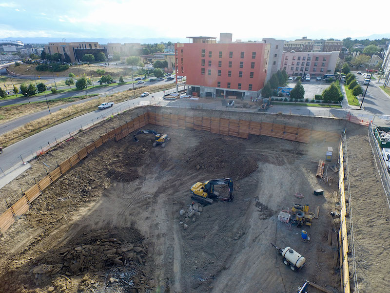
During the creation of a soldier pile wall, specific requirements need to be met to ensure strength and efficacy. The solider piles are drilled or driven vertically into the ground. Soldier Piles are generally steel beams or piles, however a variety of soldier piles are used for walls around the country when the project requires an innovative solution. Alternative sections can include precast concrete, micropiles, conventional pipe sections etc. Spacing of the vertical elements, usually between 6 and 10 feet, can occasionally even reach 12 feet apart. Once the piles are set the excavation proceeds in lifts. Lifts are generally around 5′. In difficult to lag soils such as silts or sands, with some cohesive material, the excavation height must be reduced to help prevent the material from moving into the excavation, between the soldier piles. Non cohesive soils are generally not suitable for lagging installation. While the lagging is installed, excavation is completed. Depending on the soils backfill and compaction may be used to fill in the void space located behind the lagging. Surface or contact lagging reduces the void behind the wall. In area where limiting movement is not as critical, backfilling behind the lagging may not be required.
The soldier pile system is designed to limit the horizontal movement of the soil, and structures and utilities that may exist behind the wall to safe practical limits. Horizontal movement is resisted by passive soil resistance acting on the front face of the soldier piles in the case of cantilever walls. Soldier piles can be designed as cantilever systems up to a cut height of roughly 12′. If increased stability is required, or a deeper excavation, then tiebacks can be grouted and drilled into the retained material. Additional lateral reinforcement elements may include steel struts, and or walers, placed between the soldier piles.
WHAT ARE LAGGING WALLS?
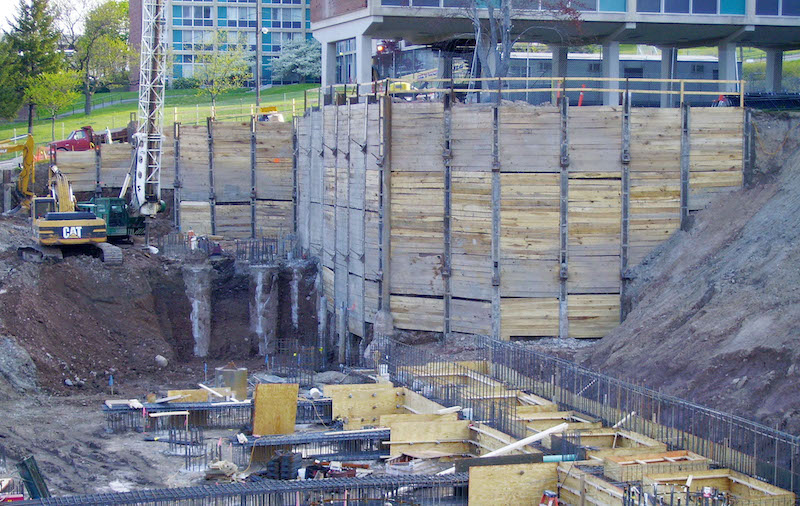
As the excavation moves forward in stages, horizontal lagging is used prevent soils from moving into the excavation. Typically, precast concrete or timber is placed behind the flanges, at times contact lagged to the front of the solider piles resulting in an earth retention system. Temporary Beam and Lagging walls are generally installed with wood lagging. Concrete lagging, or even shotcrete lagging is generally only used for permanent walls.
Lagging is important to transfer the horizontal pressure of the soil strata to the soldier piles and prevent soil flow between the soldier piles.
When the soil has stand-up time, then the lagging can be inserted from the top and placed with a downward pull. Other types of soil require the lagging to be installed on the outside of the piles continuously. When slight caving or sloughing happens, then soil or grout should be placed behind the lagging.
DETERMINING THE USE OF SOLDIER PILES AND LAGGING WALLS
Applications for the use of these retaining wall systems range from temporary projects to permanent solutions. In temporary situations, soldier pile and lagging walls can be used to support excavation during the construction phases using affordable materials and short-term solutions. Long-term results can be achieved by changing the materials and installation methods to ensure durability.
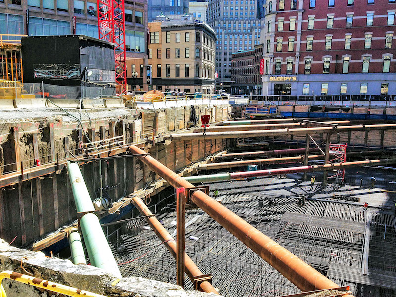
Soldier pile and lagging walls can be used in a variety of building plans. Usually, they are required in urban environments to support excavations where benched or sloped designs can’t be used.
Traditionally, the timber lagging design is used based on the experience of the designer. The Goldberg-Zoino chart is a common reference for the Federal Highway Administration. The methods are restricted based on factors such as pile spacing, soil profile, construction grade timber lagging, and depth limits. The recommended timber lagging thickness can be determined for different pile spacing, soil types, and wall heights.
This chart classifies soil in three categories. Then the thickness of the timber lagging is determined from the lagging clear span and two or three depth categories. The chart can only be used for a depth up to 60 feet, and the soil category determination is left to the designer’s judgment. This chart system doesn’t assist with certain lagging materials or varying species or grades of timber lagging.
One theory is that the active earth pressure reaches a minimum between the piles and a maximum at the soldier piles. Another theory suggests that pressure on the lagging is calculated based on half of the active earth pressure. Contrary to experience, both of these methods agree that the pressure on the lagging increases proportionally based on depth without limit.
SHOULD YOU USE SOLDIER PILE AND LAGGING WALLS?
As you compare the pros and cons of soldier piles, how do you determine if this retaining wall system is right for your construction project? Keep in mind that these systems are quite diverse. As a result, the plans can be adjusted to achieve the specific objectives of each project. Flexibility is available in the variety of materials for both the beams as well as the lagging. Geometry of the excavation as well as soil conditions will dictate, the size of the retaining walls, depth, and installation techniques. The wall plans must be tailored to match the geological conditions of the construction site.
In most situations, soldier pile and lagging systems are only used for competent soil sites. These methods are not effective for soft clay conditions or areas where the groundwater is above the excavation depth. High water table, weak soils or cohesive soils can make installation of lagging nearly impossible — which may jeopardize the facilities that are to be protected by the Earth Retention System.
LATERAL EARTH PRESSURES
A variety of lateral earth pressure diagrams have been developed over the last half century or more. Regardless of the quantity of research conducted there is no replacement for experience by a design professional for the soils at a local level. For example, varying soil conditions, unusual loads, non homogenous soils, urban fills all add to the complexity of determining lateral pressures.
For the rigid earth retention systems, it is assumed that this lateral earth pressure is constant across the wall length. In comparison with soldier pile and lagging systems, the lagging is typically less stiff compared to the steel soldier piles. The lagging will deflect, causing the soil to bridge between the stiffer elements, which causes a lower pressure placed on the lagging. In most situations, a portion of the active earth pressure is used in various pressure distributions.
APPARENT EARTH PRESSURE DIAGRAMS
An alternative option is to use diagrams based on the soil type at the location of the upper and lower ground anchors. This Apparent Earth Pressure Diagram can be constructed for both temporary and long-term loadings. Keep in mind that the calculations need to factor in the length of time since different construction techniques and materials are used for long- term durability.
Not only is the soil type factored into the diagram, but surcharge pressures and water pressures also need to be added to the diagram explicitly. This method is effective to evaluate the total lateral load for the wall.
Accurate Apparent Earth Pressure Diagrams, based on the Terzaghi and Peck methods, affect the recommended lagging thickness based on the grade of construction lumber, estimated pressures, and soil type. Precise calculations can be completed to limit displacements, which is essential to protect buildings and facilities adjacent an excavation. When in doubt, it is best to ensure the calculations are conservative to minimize future issues.
ADVANTAGES OF SOLDIER PILE AND LAGGING WALLS
Many advantages are available from this type of retaining wall construction. A few highlighted benefits include:
• Fast construction
• Lower costs compared to other retaining wall systems
• Flexibility of construction materials
• Versatility that allows adjustments to be made on the spot.
This versatility is important to accommodate construction needs as the building plans progress. Also, the simplicity of the soldier pile and lagging wall design is beneficial. Builders don’t need advanced construction techniques or knowledge for simple systems. However complex deep systems in urban environments will require expertise and experience. While many construction professionals tout the benefits of soldier pile and lagging walls, a few disadvantages need to be noted as well. For example, this design plan is often used for temporary construction, so other options should be considered for long-term durability. Additionally, improper back-filling could result in ground losses that cause surface settlements.
As mentioned earlier, this building technique is not ideal in areas with a high-water table. If this method is needed, then the plans should include details to remove the water before construction begins.
MATERIALS USED FOR SOLDIER PILES AND LAGGING WALLS
The main component of these systems involves piles placed vertically at intervals, with the lagging placed between for soil retention. This lagging can consist of metal decking, rough sawn timber, or precast concrete or sculpted shotcrete. When the excavation exceeds the depth that can be cantilevered, soldier pile and lagging systems can be created using bracing or tie-backs for deflection control and strength.
The H-piles are constructed by vibrating, driving, or drilling a hole. Then, wetsetting is used to hold the pile with a grout column found at the bottom of the excavation. These piles should be placed before excavation begins. Then the lagging is placed as the excavation advances.
Soldier piles date as far back as the 18th century and have been used in major cities around the world: New York, Berlin, London, and more. In fact, the design of the soldier pile method involves steel and timber and is often referred to as the “Berlin wall” method.
An alternative method is to use caissons, concrete piles, or circular pipes. These materials come at a higher cost though, so they aren’t quite as common compared to the steel and timber method. Determining the materials used for each project should be based on budgetary restrictions, soil conditions, construction site factors, and other elements that need to be addressed during excavation and construction.
What are soldier piles and lagging walls?
Soldier piles are drilled or driven vertically into the ground considering vertical elements like a steel beam, pile, pipe spaced between 6 to 10 feet. It is designed to limit the horizontal movement of soil excavation. A lagging wall is a system placed between soldier piles using wood, concrete, or even shotcrete to transfer the horizontal pressure to the soldier piles. These systems can be used for temporary or permanent structure construction.
What is the apparent earth pressure diagram?
An accurate apparent earth pressure diagram can be designed for temporary and long-term loadings. It is more detailed information based on Terzaghi and Peck methods with types of soil, average layer determination, surcharge pressure, water pressure, and soil parameters. It is an important tool to determine lagging thickness, limit displacement, and cost optimization of materials used.