Chapter 9 – Slurry Displacement Piles
- Chapter 1 – Foundation Investigations
- Chapter 4 – Footing Foundations
- Chapter 5 – Pile Foundations
- Chapter 6 – Cast-In-Drilled-Hole Piles
- Chapter 7 – Driven Piles
- Chapter 8 – Static Pile Load Testing and Pile Dynamic Analysis
- Chapter 9 – Slurry Displacement Piles
- Chapter 11 – Ground Anchors & Soil Nails
- Chapter 12 – Cofferdams and Seal Courses
- Chapter 14 – Specialty Piles and Special Considerations for Pile Foundations
Foundations Manual by Caltrans
9.1 Introduction
A slurry displacement pile is a Cast-In-Drilled-Hole (CIDH) pile where a drilling fluid is introduced into the excavation concurrently with the drilling operation. The drilling fluid, also referred to as slurry or drilling slurry, is used to prevent caving of unstable ground formations and intrusion of groundwater into the drilled hole. The drilling slurry remains in the drilled hole until it is displaced by concrete, which is placed under the drilling slurry through a rigid delivery tube.
Because the slurry displacement method, also referred to as the wet method, is a specific construction method for the construction of CIDH piles, the reader is advised to review Chapter 6, Cast-In-Drilled-Hole Piles, as it contains information about inspection duties and responsibilities of the Engineer for construction of all CIDH piles. This chapter contains modifications to inspection duties and responsibilities of the Engineer necessary for the construction of CIDH piles using the slurry displacement method.
9.1.1 History
The use of drilling slurry is commonly associated with methods used by the oil well drilling industry for more than 100 years, which provided much of the technical and practical knowledge concerning their use in drilled foundation applications. Use of the slurry displacement method for constructing drilled shafts began in Texas in the years following World War II. This early method involved the use of soil-based drilling slurries to advance drilled holes deeper than they could have without, after which a casing was used to stabilize the drilled hole for shaft construction. In the 1960’s, processed clay mineral slurry was introduced as a means of eliminating the need for casing to stabilize the drilled hole. However, the properties of the mineral drilling slurries were not controlled. Initial information on the properties of mineral drilling slurries was obtained from the Reese and Touma Research Report, which was a cooperative research program conducted in 1972 by the University of Texas at Austin and the Texas Highway Department. Due to the numerous failures that occurred, in the mid-1970’s more attention was paid to the physical properties of mineral drilling slurries and appropriate methods of preparing and recirculating drilling slurries.
There are still many unknowns about the use of drilling slurries, among them the effect of the drilling slurry on the ability of a pile shaft to develop skin friction. Research on the shaft side resistance; however, this impact can be avoided by following proper construction procedures. On the other hand, research has also shown that development of side resistance does not appear to be a problem with the use of synthetic slurry, with the possible exception of hard rock where the sides of the drilled hole are smooth. The design method used by Caltrans for determining the pile capacity adequately accounts for possible loss of pile capacity when drilling slurry is used. Research funded in part by the Federal Highway Administration (FHWA) is ongoing at universities around the United States. Caltrans has also conducted research on several contracts in recent years, which lead to the development and continual improvement of contract specifications for use of the slurry displacement method of CIDH pile construction.
Processed clay mineral slurries are considered environmentally hazardous and are difficult to dispose of. In the 1980’s, the drilled shaft industry began a trend towards the use of synthetic drilling slurries. These drilling slurries are less hazardous to the environment and are easier to dispose of.
Caltrans first used the slurry displacement method on a construction contract in 1984 and has increasingly used this method since then. A change in Caltrans seismic design philosophy has resulted in the use of more and larger CIDH piles. Because of this, ground conditions have become less of a factor in the pile type-selection process. Other factors such as lower construction costs and construction in urban environments with restricted access and noise limitations have also led towards the expanded use of CIDH piles. Because of these factors, Caltrans started inserting the slurry-displacement method specifications into all contracts with CIDH piles in 1994.
9-2 Slurry Displacement Method
The slurry displacement method of construction is similar to that of ordinary CIDH pile construction until groundwater or caving materials are encountered. When groundwater or caving materials are encountered during the drilling operation, the Contractor must have a plan in place to decide whether to use a casing to stabilize the drilled hole, dewater the drilled hole, or drill the hole and place concrete under wet conditions using the slurry displacement method. In most cases, the site conditions are known to be wet or unstable. These conditions should have been shown on the Log of Test Borings (LOTB) or in the Foundation Report. Sometimes experience on adjacent projects may also give an indication of the site conditions.
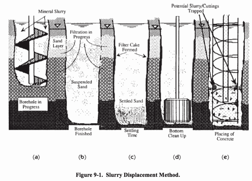
Drilling slurries are generally introduced into the drilled hole as soon as groundwater or caving materials are encountered. As drilling continues to full depth, the drilling slurry is maintained at a constant level at least 10 feet above the piezometric head until the tip elevation of the drilled hole is reached (Figure 9-1(a)). Because the drilling operation mixes soil cuttings with the drilling slurry, it is necessary to remove the soil cuttings from the drilling slurry. Depending on the type of drilling slurry used, removing the soil cuttings may be accomplished by physically cleaning the drilling slurry, or by allowing a settlement period for the soil cuttings to settle out of the drilling slurry (Figure 9-1(c)). If the drilling slurry is cleaned such that its physical properties are within the specified limits for the particular type of drilling slurry, the bottom of the drilled hole is cleaned of any settled materials using a cleanout bucket (Figure 9-1(d)). Since the action of the cleanout bucket may cause soil cuttings to contaminate the drilling slurry, cleaning the bottom of the drilled hole and the drilling slurry may take several iterations. Additional cleanings of settled materials from the bottom of the drilled hole may be performed with a cleanout bucket, pumps, or an airlift. After the final cleaning has been accomplished, the drilling slurry is retested to make sure its properties are within the specified limits. Once the drilling slurry is ready, the pile bar reinforcement cage may be placed. The slurry is again retested immediately prior to concrete placement and the bottom of the hole is re-cleaned using a pump or airlift. Once the slurry’s physical properties are within the specified limits and the bottom of the hole is clean, concrete is placed, either by a rigid tremie tube or by a rigid pump tube delivery system. Concrete is placed through the tube(s), starting at the bottom of the drilled hole (Figure 9-1(e)). The tip of the rigid delivery tube is maintained at least 10 feet below the rising head of concrete. As concrete is placed, the displaced drilling slurry is pumped away from the hole and prepared for reuse or disposal. Concrete placement continues until the head of concrete rises to the top of the pile and is then wasted until all traces of settled material or drilling slurry contamination in the concrete are no longer evident. Under circumstances where contaminated concrete cannot be wasted from the top of the pile, such as having a pile construction joint within a permanent casing below grade, pile concrete is placed to a predetermined level above the planned concrete placement elevation, and the contaminated concrete above the planned concrete placement elevation is either mucked out immediately after placement or chipped out at a later time.
 9-3 Principles of Slurry Usage
All slurries keep excavations open by the use of positive hydrostatic pressure. In order to exert hydrostatic pressure against the walls of an excavation, a pressure transfer medium must be present. With mineral slurries (e.g. bentonite mud) the deposited filter cake of clay solids on permeable formations is the pressure transfer mechanism (the thing against which the hydrostatic pressure can push). In the case of properly formulated synthetic slurries, the pressure transfer mechanism is the zone of viscous permeation that surrounds the excavation. This zone is preferably permeated (and plugged) by viscous polymer slurry. The depth of the zone around the excavation can be inches or feet.
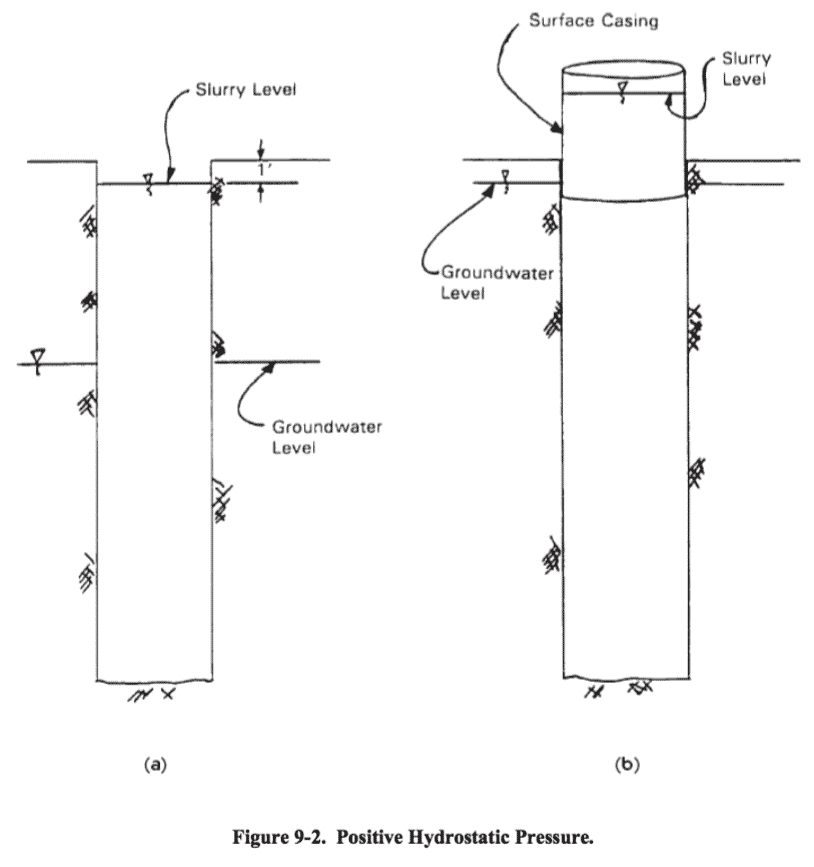
Positive hydrostatic pressure refers to the excess pressure exerted by a column of fluid against the interstitial or pore pressure of a soil layer (Figure 9-2(a)). A column of water 33 feet tall exerts a hydrostatic pressure of 1.0 atmosphere or 14.7 pounds per square inch. It has been determined by experience that a positive hydrostatic pressure of about 6 to 7 feet of water head is normally sufficient to keep an excavation open. This is equivalent to 0.2 atmospheres or about 3 pounds per square inch. A more useful way to consider 3 pounds per square inch is that it equals 432 pounds per square foot of excavation wall area. This is apparently sufficient to keep most holes open when proper operating practices are in use.
“Positive hydrostatic pressure” also refers to hydrostatic pressure above and beyond that exerted inward on an excavation by ground water (Figure 9-2). Thus if the static ground water table is at 15 feet below ground level, and if we want to maintain a column of slurry 7 feet higher than that, we will need to keep the slurry level at 8 feet below ground level. If excessive fluid loss is not a concern, we may want to keep the hole full of fluid, but this is probably not necessary in most cases. Excessive hydrostatic pressure can accelerate non-useful, unwanted loss or permeation of slurry into granular permeable soil layers.
As mentioned previously, the filter caking process created by mineral or solid-laden slurries is called filtration. When drilling slurry is applying positive hydrostatic pressure to the sides of the drilled hole, some of the drilling slurry and soil cuttings may be forced out of the excavation and into the ground formation. When this material enters the formation, particles of the drilling slurry may be trapped or “filtered” by the individual soil grains of the formation. This process results in the development of filter cakes on the sides of the drilled hole. These filter cakes are referred to as “mudcakes” and help to temporarily stabilize the sides of the drilled hole.
The filtration process is dependent upon many variables. These include the nature of the ground formation, the type of mineral drilling slurry used, the amount of time the drilling slurry is in the drilled hole, the presence of contaminants or groundwater in the ground formation, and the chemical additives used in the drilling slurry, just to name a few. The nature of the ground formation and the amount of time the drilling slurry is in the drilled hole are the two important variables.
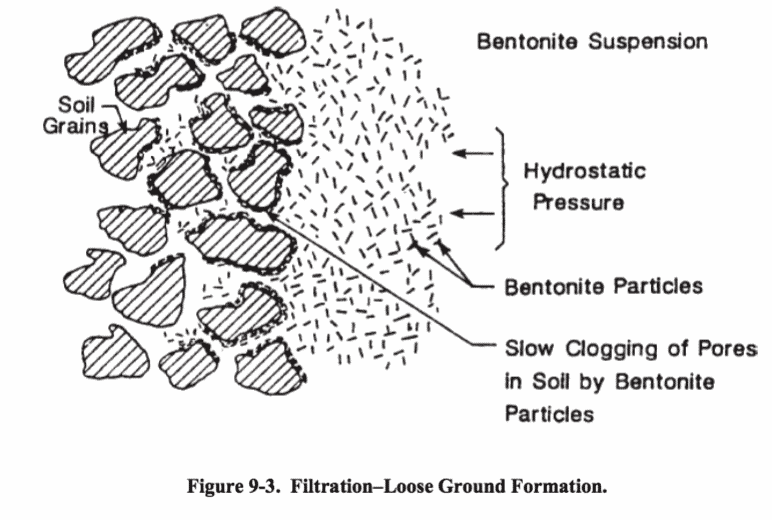
The nature of the ground formation has an effect on the thickness of the filter cake that mineral slurries or other solids-laden slurries develop on the sides of the drilled hole. In general, thicker cakes will form on permeable granular ground formations, such as sands. Since the pore spaces between the individual soil grains are larger, drilling slurry with entrained soil particles can infiltrate further into the ground formation driven by the same positive hydrostatic pressure (Figure 9-3). Eventually, the infiltration slows as drilling slurry and particles build up against and beyond the exposed faces of the permeable formations. In tighter ground formations, such as dense sands and cohesive soils, the pore spaces between the individual soil grains are much smaller. The drilling slurry particles tend to fill in the pore spaces at the exposed wall face preventing further infiltration (Figure 9-4). Drilling slurry cannot be forced into the ground formation by positive hydrostatic pressure. This causes the build-up of the filter cake to cease; resulting in a thinner filter cake than would be observed in looser ground formations.
The amount of time that the drilling slurry is in the drilled hole also has a direct effect on the thickness of the filter cake that develops on the sides of the drilled hole. As long as positive hydrostatic pressure is continuous, the build-up of filter cake will continue so long as the infiltration continues. In general, the longer the drilling slurry is present in the drilled hole, the more filter cake will accumulate on the sides of the drilled hole. Sometimes this results in the presence of excess filter cake buildup, which must be removed before concrete can be placed in the drilled hole.
The important thing to remember about filtration is that it mainly pertains to mineral slurries or other solid-laden slurries and its filter cake helps to temporarily stabilize the sides of the drilled hole before concrete is placed. Filter cake is not meant to be left in place during concrete placement operations. If the filter cake is thin enough, the rising column of concrete will scrape it off the sides of the drilled hole. However, if the filter cake has excessive thickness, the rising column of concrete may not scrape all of it off the sides of the drilled hole. The remaining filter cake may act as a slip plane between the pile concrete and the sides of the drilled hole, resulting in the reduced skin friction capability of the pile. Excess filter cake must be removed prior to concrete placement.
With synthetic slurries, these fluids permeate and exert hydrostatic pressure against the walls of an excavation in order to keep the excavation open during drilling or digging and concrete placement. Synthetic slurries consist of very long, chain-like hydrocarbon molecules (polymers) that do not deposit a conventional wall cake or filter cake as with mineral slurries because the fluids are not laden with fine plate-shaped particles, such as bentonite.
Instead, a properly prepared synthetic polymer slurry permeates granular soils to a relatively shallow penetration around an excavation with long, hair-shaped strands of slurry molecules (Figure 9-5). This permeation has a gluing effect and stabilizes an excavation due to drag forces and cohesion formed from the binding of the soil particles in the formation by the polymer strands that tend to keep the soil particles in place.
-
 SPW911 Sheet Pile Design Software
Rated 5.00 out of 5$150.00 – $599.99Price range: $150.00 through $599.99
 -
 Sheet Pile Design (PDF Download)
Rated 5.00 out of 5$89.00
 -
 Pile Driving (PDF Download)
$89.00
-
 Marine Construction Volumes 1 & 2 (PDF Download)
$157.00
-
 Pile Driving (Book)
$89.00


