Chapter 7 – Driven Piles
- Chapter 1 – Foundation Investigations
- Chapter 4 – Footing Foundations
- Chapter 5 – Pile Foundations
- Chapter 6 – Cast-In-Drilled-Hole Piles
- Chapter 7 – Driven Piles
- Chapter 8 – Static Pile Load Testing and Pile Dynamic Analysis
- Chapter 9 – Slurry Displacement Piles
- Chapter 11 – Ground Anchors & Soil Nails
- Chapter 12 – Cofferdams and Seal Courses
- Chapter 14 – Specialty Piles and Special Considerations for Pile Foundations
Foundations Manual by Caltrans
7-1 Introduction
Driving piles for structure foundations has occurred for centuries. Originally, timber was used for piles. In 1897, the first concrete piles were introduced in Europe, and the Raymond Pile Company drove the first concrete piles in America in 1904. These new concrete piles were designed for 30 tons and over. Currently, steel H-Piles and pipe piles are also used. These piles can be expensive but their ability to transfer greater loads has made them economical, particularly in large structures.
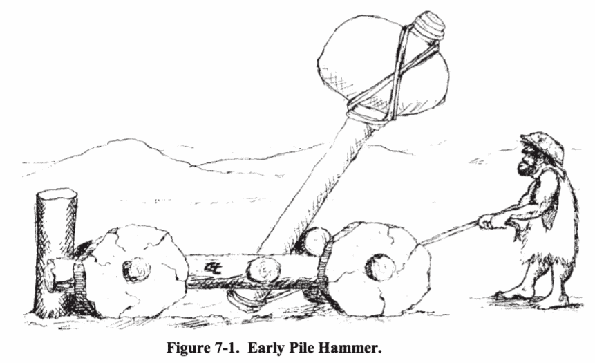
Pile driving is the operation of forcing a pile into the ground thereby displacing the soil mass across the whole cross section of the pile. Historically, the oldest method of driving a pile, and the method most often used today, is by use of an impact type hammer.
The first hammers known to be used were drop hammers which were used exclusively until the invention of the steam engine, which eventually resulted in steam hammers. Subsequent technological advances have led to the development of air, diesel, hydraulic powered impact hammers, plus vibratory and sonic hammers. Modern day requirements for construction have also resulted in various adaptations of the aforementioned pile driving techniques.
This chapter is intended to outline specifications, equipment, techniques, and safety items that a bridge engineer can expect to encounter during typical pile driving operations.
7-2 General Specifications
The following is a partial list of some of the more important pile driving specifications. Before starting a project, the Engineer should thoroughly review the Standard Specifications for general requirements and the special provisions for information tailored to the needs of the specific project.
Typical sections of the Standard Specifications (SS) to be reviewed are as follows: • Earthwork (SS, Section 19).
- Piling (SS, Section 49).
- Wood and Plastic Lumber Structures (SS, Section 57).
The following are taken from the Standard Specifications and should be reviewed as applicable:
-
-
- In embankment areas where piles are to be placed or driven, do not use material containing rocks, broken concrete, or other solid materials larger than 4 inches in greatest dimension.1
- For bridge footings to be constructed in embankment, construct the embankment to the grading plane elevation and extend the finished slope to the grading plane before:
- Excavating for footings.
- Driving piles or drilling holes for Cast-in-Place (CIP) piles.
- Where an embankment settlement period is specified, and before the end of the settlement period, do not:
- Excavate for abutments, bent footings, wingwalls, or retaining wall footings.
- Drive foundation piles or drill holes for CIP piles.
- Piling must have sufficient length to attain the specified trip elevation shown and extend into the pile cap or footing.4
- Install driven piles using an authorized impact hammer. The impact hammer must be:
- Steam, hydraulic, air, or diesel.
- Able to develop sufficient energy to drive the pile at a penetration rate of not less than 1/8 inch per blow at the nominal driving resistance shown.
- For piles to be driven through embankments constructed under the Contract, drive piles through predrilled holes where the depth of the new embankment at the pile location is in excess of five feet. The hole diameter must be at least 6 inches larger than the greatest dimension of the pile cross section. After driving the pile, fill the space around the pile to the ground surface with dry sand or pea gravel.
- Except for piles to be load tested and sheet piles, drive piles to at least the nominal driving resistance and the specified tip elevation shown.
-
The preceding specifications indicate that there are two different pile driving acceptance criteria: (1) A specific pile tip penetration, and (2) a prescribed bearing value. In all but a few cases, both of these criteria must be met in order to accept the pile.
7-3 Pile Driving Definitions
The following is a partial list of some of the definitions unique to the pile driving trade. These are the most common terms used and should be of benefit to those new to pile driving work. Refer to Figures 7-2 through 7-8 for the illustration of the defined terms.
Table 7-1. Pile Driving Terms and Definitions.
| TERM | DEFINITION | ||||
| Anvil | The bottom part of a hammer that receives the impact of the ram and transmits the energy to the pile. | ||||
| Butt of Pile | The term commonly used in conjunction with the timber piles–the upper or larger end of the pile, the end closest to the hammer. | ||||
| Cushion Blocks | Usually plywood pads placed on top of precast concrete piles to eliminate spalling. | ||||
| Cushion Pad | A pad of resilient material or hardwood placed between the drive cap insert, or helmet, and drive cap adapter. | ||||
| Drive Cap Adapter | A steel unit designed to connect specific type of pile to a specific hammer. It is usually connected to the hammer by steel cables. | ||||
| Drive Cap Insert | The unit that fits over the top of pile, holding it in line and connecting it to the adapter. | ||||
| Drive Cap System | The assembled components used to connect and transfer the energy from the hammer to the pile. | ||||
| Follower | An extension used between the pile and the hammer that transmits blows to the pile when the pile head is either below the reach of the hammer (below the guides/leads) or under water. A follower is usually a section of pipe or “H” pile with connections that match both the pile hammer and the pile. Since the follower may absorb a percentage of the energy of the hammer, the contract specifications8 require the first pile in any location be driven without the use of a follower so as to be able to make comparisons with operations utilizing a follower. In water, the first pile to be driven should be one sufficiently long to negate the need for the follower. The information from the first pile can be used as base information when using the follower on the rest of the piling. Beware of soil strata that may change throughout the length of a footing. Underwater hammers and extensions to the leads can be used as alternatives to driving with a follower. | ||||
| Hammer Energy | The amount of energy available to be transmitted from the hammer to the pile. Usually measured in foot-pounds. |
| Leads | A wooden or steel frame with one or two parallel members for guiding the hammer and piles in the correct alignment. There are three basic types of leads: • Fixed, which are fixed to the pile rig at the top and bottom. Refer to Figure 7-4. • Swinging, which are supported at the top by a cable attached to the crane. Referto Figure 7-5. • Semi-Fixed or Telescopic, which are allowed to translate vertically with relationto the boom tip. Refer to Figure 7-6. |
| Mandrel | A full-length steel core set inside a thin-shell casing. It increases the structural capacity of the casing so that it can be driven. It helps maintain pile alignment and prevents the casing from collapsing. It is removed after driving is completed and prior to placing reinforced concrete. |
| Moonbeam | A device attached to the end of a lead brace that allows a pile to be driven with a side batter. |
| Penetration | The downward movement of the pile per blow. |
| Pile Butt | A member of the pile crew other than the operator and oiler. |
| Pile Gate | A hinged section attached to the pile leads, at the lower end, which acts to keep the pile within the framework of the pile leads. |
| Pile Hammer | The unit that develops the energy used to drive piles, the two main parts of which are the ram and the anvil. |
| Pile Monkey | A device used to position the pile in the leads beneath the hammer. |
| Pile Rig | The crane used to support the leads and pile driving assembly during the driving operation. |
| Ram | The moving parts of the pile hammer, consisting of a piston and a driving head, or driving head only. |
| Rated Speed | The number of blows per minute of the hammer when operating at a particular maximum efficiency. |
| Spudding | Spudding is the driving of a short and stout section of pile-like material into the ground to punch through or break up hard ground strata to permit pile driving. Used extensively in the driving of timber piles. |
| Striker Plate | A steel plate placed immediately below the anvil. Also known as an anvil. |
| Stroke | The length of fall of the ram. |
| Tip of Pile | The first part of the pile to enter the ground. |
7-4 Hammer Types
Many different types of pile driving hammers are used in the pile industry today. In the past, single acting diesel hammers were used on most projects. With the onset of retrofit work and new construction in areas with low overhead clearances, the use of double/differential acting hammers and hammers that require only a limited overhead clearance are finding their way to the job site. Site specific construction challenges, be it limited space, noise levels, or unusual tip or bearing requirements will tend to dictate the type of hammer used.
The pile hammer is not only the production tool for the Contractor, it is also a measuring device for the Engineer. The energy transmitted to the pile advances it toward the specified tip elevation. The amount of energy and the penetration per blow can be used to determine the bearing capacity of the pile. A working knowledge of pile hammers, their individual parts and accessories, and their basis for operation and the associated terminology is essential for the Engineer.
Following is a partial list of different types of hammers available today with a brief description of their limiting characteristics.
7-4.1 The Drop Hammer
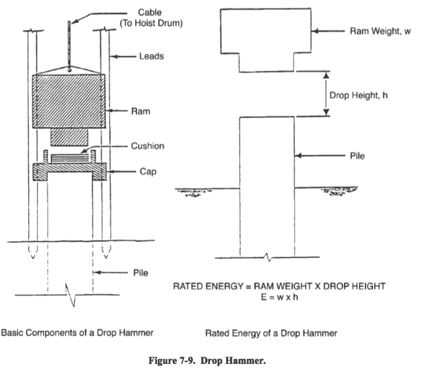
Although the drop hammer was invented centuries ago, it is still in use today. Although modernized somewhat, the basic principle of operation remains the same. A weight is lifted a measured distance by means of a rope or cable and allowed to freefall, or drop, and strike a pile cap block. The available potential energy is calculated by multiplying the weight and the distance of the fall.
One variation of the drop hammer currently finding its way to the job site is one that requires only a minimal amount of headroom. The idea utilizes a closed-ended pipe pile with a large enough diameter to allow the drop hammer run inside the pipe’s walls. The hammer impacts onto a “stop” built into the bottom, inside of the pipe pile. As the pile is driven, the impact occurs near the tip of the pile. In fact the pile is actually pulled down into position in lieu of being pushed. This configuration minimizes the need for the additional overhead clearance (leads, crane, etc.).
Drop hammers are not typically used and are permitted only when allowed by the special provisions.
When using a drop hammer the Engineer should:
| NO. | ITEM DESCRIPTION | ||||
| 1 | Ensure that you have the correct weight for the hammer being used. If in doubt, have it weighed. | ||||
| 2 | Ensure the drop hammer lead sections are properly aligned and that all lead connections are properly tightened. | ||||
| 3 | Ensure, while in use, that the hoist line is paying out freely. | ||||
7-4.2 Single Acting Steam/Air Hammer
The single acting steam/air hammer is the simplest powered hammer. Invented in England by James Nasmyth in 1845, it has been used in this country since 1875.
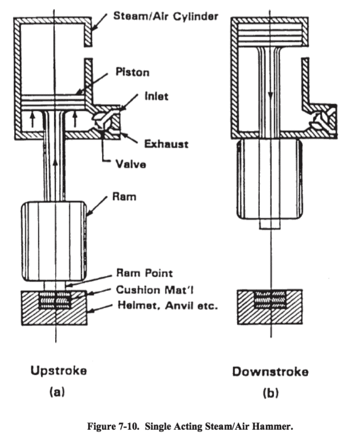
As shown in Figure 7-10, the hammer consists of a heavy ram connected to a piston enclosed in a chamber. Steam or air is supplied to lift the ram to a certain height. The lifting medium is then exhausted and the ram falls by its own weight. The rated energy of the single acting steam/air hammer is calculated by multiplying the ram weight (total weight of all moving parts: ram, piston rod, keys, slide bar, etc.) times the length of fall (stroke).
These hammers have a stroke of 30 to 40 inches and operate at 60 to 70 strokes per minute. They are rugged and deliver a relatively low velocity heavy blow. The only necessary changes in operation from steam to air are a change in the general lubrication and the hose line specification.
When using a single acting steam/ air hammer the Engineer should:
| NO. | ITEM DESCRIPTION |
| 1 | Have the manufacturer’s current specifications for the type and model of hammer being used. |
| 2 | Ensure all required parts of the hammer are intact and in good operating condition. |
7-4.3 Double Acting Steam/Air Hammer
The double acting steam/air hammer employs steam or air, not only to lift the piston to the top of its stroke, but also to accelerate the piston downward faster than by gravity alone. The additional energy put into the downward stroke by the compressed air/steam increases the effectiveness of the hammer. The advantage of the double-acting hammer is that stroke lengths can be reduced making them ideal in low overhead clearance situations. The stroke typically ranges from 10 to 20 inches, or about half that of a single acting hammer. The blow rate is more rapid than the single acting hammer, somewhere between 120 and 240 blows per minute. Refer to Figure 7-11. The rated available energy of the double acting steam/air hammer is calculated by multiplying the ram weight times the length of stroke and adding the effective pressure acting on the piston head during the downstroke.
In addition to being an ideal hammer in low overhead situations, this type of hammer does not use a cushion block between the ram and the anvil block. Another advantage is that some of these hammers are entirely enclosed and can be operated submerged in water. With this type hammer, it is essential that the hammer is operating within the manufacturer’s specifications. Since pressure is used to drive the hammer, it’s imperative that operating pressures are known. The pressures recorded will correlate to an impact energy found on a chart/table provided with the hammer.
-
 SPW911 Sheet Pile Design Software
Rated 5.00 out of 5$150.00 – $599.99Price range: $150.00 through $599.99
 -
 Sheet Pile Design (PDF Download)
Rated 5.00 out of 5$89.00
 -
 Pile Driving (PDF Download)
$89.00
-
 Marine Construction Volumes 1 & 2 (PDF Download)
$157.00
-
 Pile Driving (Book)
$89.00


