Chapter 6 – Cast-In-Drilled-Hole Piles
- Chapter 1 – Foundation Investigations
- Chapter 4 – Footing Foundations
- Chapter 5 – Pile Foundations
- Chapter 6 – Cast-In-Drilled-Hole Piles
- Chapter 7 – Driven Piles
- Chapter 8 – Static Pile Load Testing and Pile Dynamic Analysis
- Chapter 9 – Slurry Displacement Piles
- Chapter 11 – Ground Anchors & Soil Nails
- Chapter 12 – Cofferdams and Seal Courses
- Chapter 14 – Specialty Piles and Special Considerations for Pile Foundations
Foundations Manual by Caltrans
6-1 Description
Few terms are as self-descriptive as the one given to the Cast-In-Drilled-Hole (CIDH) pile. They are simply reinforced concrete piles cast in holes drilled to predetermined elevations. Much experience has been gained with this pile type because of its extensive use in the construction of bridge structures. While they probably are the most economical of all commonly used piles, their use is generally limited to certain ground conditions.
CIDH piling can be grouped into two categories:
- CIDH piling placed in “dry” conditions, usually without inspection pipes (drymethod).
- CIDH piling placed under slurry or with the use of temporary casing to control groundwater, always with inspection pipes (wet method).
This chapter is applicable for both the dry and wet method of CIDH pile construction. Chapter 9, Slurry Displacement Piles, provides supplemental information on the wet method of CIDH pile construction. Note that piling with a diameter greater than 24′′, which is de-watered with the help of a temporary casing, requires inspection pipes even if the piling is placed in “dry” conditions.
The ground formation in which the holes for CIDH piles are to be drilled must be of such a nature that the drilled holes will retain their shape and will not cave in before or during concrete placement. Because of cave-ins and concrete placement difficulties, these piles are not recommended for use as battered piles. Other pile types should be considered where groundwater is present, unless dewatering can be done with a reasonable effort and concrete can be placed without a permanent casing. If groundwater or caving conditions are present, the piles can be constructed by the slurry displacement method if permitted in the contract specifications. The slurry displacement method is described in detail in Chapter 9, Slurry Displacement Piles,.
The Standard Specifications use three definitions to classify the condition of a drilled hole. A dry hole is defined as a drilled hole that requires no work, such as pumping or other means, to keep it free of water. This means there must be no standing or accumulating water in the bottom of the drilled hole, although the material at the bottom of the drilled hole may be damp or wet. A dewatered hole is defined as a drilled hole where water may be present, but accumulates at a rate of less than 12 inches per hour and can be controlled by pumps or other means to reduce the amount of accumulated water to 3 inches or less at the time of concrete placement. The dry method of construction can be used for dry or dewatered holes. A wet hole is defined as a drilled hole where water accumulates at a rate of more than 12 inches per hour or where a temporary casing is used to reduce the rate of water accumulation to less than 12 inches per hour. For a wet hole, inspection pipes are required and the wet method of construction is almost always necessary.
6-2 Specifications
The contract specifications contain the information necessary to administer the construction of CIDH piles. Standard Specification Section 49 contains information on the construction methods. Section 52 contains information on pile bar reinforcement. Section 90 contains information on the concrete mix design, transportation of concrete, and curing of the concrete used for CIDH piles.
The Special Provisions contain project-specific requirements and revised standard specifications. Because the CIDH pile specifications are continually updated and ground conditions vary from project to project, it is very important that the engineer carefully review the Special Provisions and discuss with the Contractor.
6-3 Drilling Equipment
The drilling auger is the most commonly used drilling tool for drilling holes for CIDH piles. Augers may be used in a variety of soil and rock types and conditions.
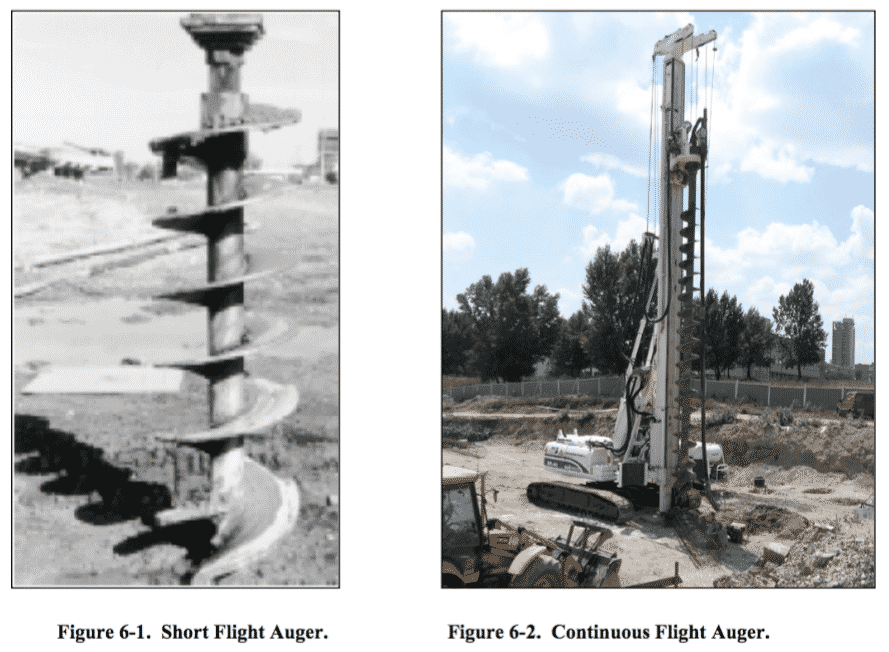
There are two basic varieties of augers–the standard short section (Figure 6-1) and continuous flight (Figure 6-2). Both have flights of varying diameter and pitch.
6-3.1 Continuous Flight Augers
Continuous flight augers have flight lengths that are longer than the hole to be drilled. They are generally lead-mounted. The power unit is located at the top of the auger and it travels down the leads with the auger as the hole is drilled. Drilling is performed in one continuous operation. As the auger moves down the hole, the drilling action of the flights forces the drill cuttings up and out of the hole. Hence, much material has to be shoveled away from around the drilled hole. Continuous flight augers are most commonly used for short piles, such as those used to support soundwalls or standard retaining walls, or for pre-drilling driven piles. They may also be used where overhead clearance is not a problem.
Short flight augers are powered by “Kelly Bar” units fixed to the drill rig. The lengths of these augers generally vary between 5 and 8 feet. The auger is attached to the end of the Kelly Bar and, as drilling progresses; the auger (and material carried on the flights) must be removed frequently. After the auger is removed from the drilled hole, the material is “spun” off the flights onto a spoil pile and the operation is repeated. Short flight augers are generally used for smaller diameter piles (less than 48′′ in diameter), although they have been successfully used for larger diameter piles.
6-3.3 Single Flight and Double Flight Augers
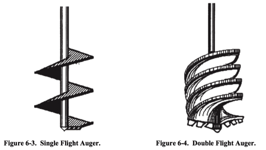
There is a variety of different auger shapes/styles used in different situations. Augers may be single flight (Figure 6-3) or double flight (Figure 6-4). Double flight augers are better balanced than single flight augers and are more useful when alignment and location of the drilled hole are important due to clearance or right-of-way problems. Soil augers are equipped with a cutting edge that cuts into the soil during rotation. The drill cuttings are carried on the flights as the auger is removed from the drilled hole and are then “spun” off. The pitch of the flights can vary and should be chosen for the type of material encountered. Soil augers may not work well in cohesionless materials, as the soil may not stay on the flights during auger extraction. They may also have issues in highly cohesive materials where the auger may become clogged.
6-3.4 Rock Augers
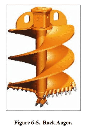
Rock augers (Figure 6-5) differ from soil augers in that they are equipped with high- strength steel cutting teeth that can cut through soft rock. These augers typically have flights with a very shallow pitch so that rock pieces, cobbles and boulders can be extracted. For this reason, rock augers are generally the preferred tool for drilling in materials that have a high concentration of cobbles or boulders.
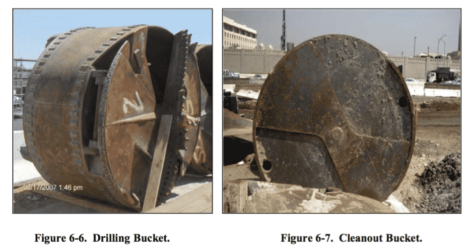
Drilling buckets (Figure 6-6) are drilling tools used when augers are not able to extract material from a drilled hole. This can happen when wet materials or cohesionless materials are encountered. Drilling buckets may also be appropriate when heavy gravel or cobbles are encountered. Drilling buckets have a cutting edge that forces material into the bucket during rotation. When the drilling bucket is full, the bucket is spun in the direction opposite of drilling, which closes the built-in flaps. This prevents the cuttings from falling out of the bucket. The bucket is then extracted from the drilled hole and emptied.
6-3.6 Cleanout Buckets
Cleanout buckets (Figure 6-7) are specialized drilling buckets that are used to clean loose materials from the bottom of a drilled hole and to flatten the bottom. This ensures that the tip of the pile is founded on a firm flat surface. These buckets have no cutting teeth but are similar to drilling buckets in other aspects. Figures 6-6 and 6-7 show the difference between the drilling bucket and the cleanout bucket. Specialized cleanout buckets can be used to extract loose materials when groundwater or drilling slurry is present. These buckets, referred to as “muckout” buckets, allow fluid to pass through them while retaining the loose materials from the bottom of the drilled hole.
6-3.7 Core Barrels
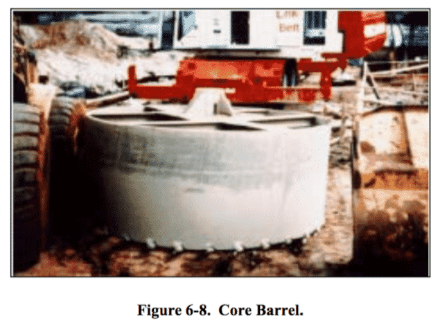
Core barrels (Figure 6-8) are used to drill through hard rock formations, very large boulders, or concrete. This type of drilling tool consists of a steel cylinder with hard metal cutting teeth on the bottom. Rock cores are broken off and extracted from the drilled hole as a single unit, or may be broken up with a rock breaker and then extracted with a drilling bucket or clamshell.
6-3.8 Down-Hole Hammers
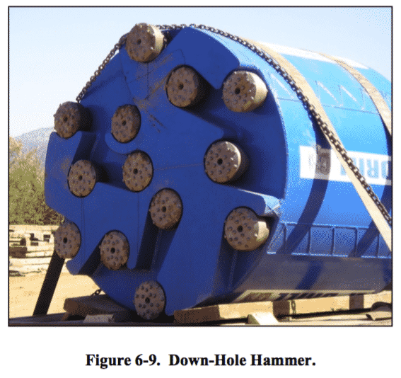
Down-hole hammers (Figure 6-9) are also used to drill through hard rock formations. This type of drilling tool uses compressed air or hydraulic-powered percussion drilling heads to pulverize the formation and blow the resulting debris from the drilled hole.
6-3.9 Rotators and Oscillators
Rotators (Figure 6-10) and oscillators (Figure 6-11) are specialized drilling equipment used to advance a drilled hole through difficult ground formations. Each machine uses a hydraulic-powered apparatus to simultaneously rotate and push down on a drilling casing. Drilling casings are sections of steel pipe, usually 20 feet in length, designed specifically for the rotator or oscillator model, with attachments for cutting teeth or splicing of additional sections. Additional sections of drilling casing are attached as the drilled hole is advanced to tip. As the drilled hole is advanced, the materials within the drilling casing are extracted using a clamshell or drilling bucket. The major difference between a rotator and an oscillator is that the rotator rotates the drilling casing in one direction, while the oscillator rotates the drilling casing in two directions, never making a complete rotation in either direction. The advantage provided by the rotator and oscillator is the drilling casing provides a temporary casing that preserves the integrity of the drilled hole, even in unstable or wet ground formations. The drilling casing remains in the drilled hole until pile concrete is placed, at which time the drilling casing is extracted from the drilled hole in a similar manner as any other temporary steel casing as described below.
6-3.10 Reverse Circulation Drilling Equipment
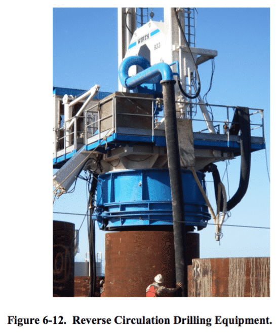
Reverse circulation drilling equipment (Figure 6-12) is used to advance a drilled hole through difficult wet ground formations. The advantage of reverse circulation is that very deep holes can be advanced without the need to cycle in and out of the hole with the drill tool to remove cuttings. The drilled hole must be full of water or other drilling fluids. The drilling head is self-contained and is driven hydraulically or by compressed air. As the hole is advanced, the drill cuttings are suspended in the water or drilling fluid. The water or drilling fluid is continuously circulated out of the drilled hole, where the drill cuttings are removed and disposed, and then re-circulated back into the drilled hole to repeat the process.
6-3.11 Temporary Steel Casings
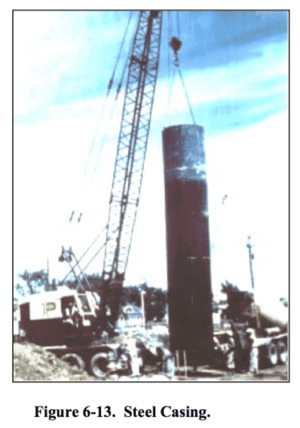
Temporary steel casings (Figure 6-13) are used to support drilled holes when unstable conditions are encountered. Various methods are used to advance steel casings into the hole. Among them, spinning the casing with the Kelly Bar while applying some vertical force, driving the casing with whatever means are available as the hole is drilled, or using a vibratory hammer. Steel casings are generally extracted from the hole in the manner specified in the contract specifications as concrete is placed.
6-3.12 Drilling Rigs
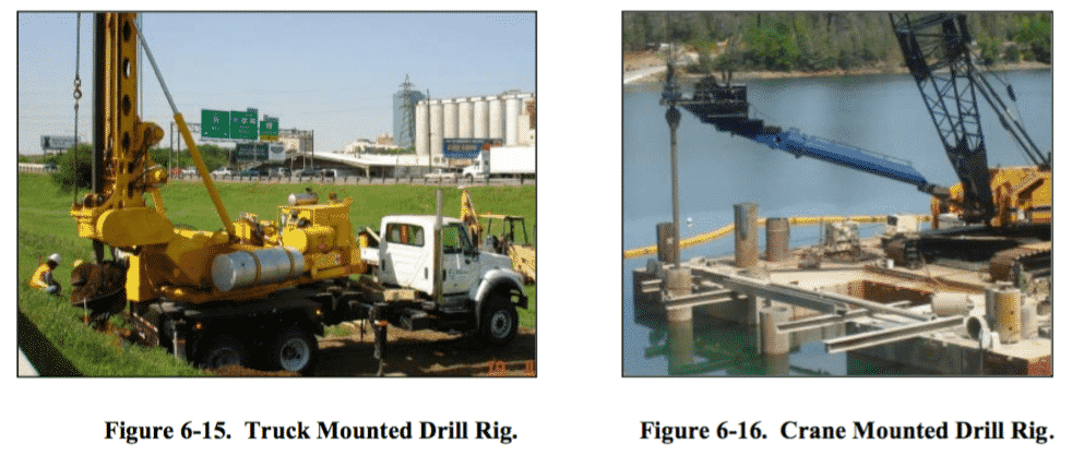
Drilling is performed almost exclusively with portable drilling rigs. These units can be self-propelled crawler mounted (Figure 6-14), truck-mounted (Figure 6-15), or crane- mounted (Figure 6-16).
6-4 Drilling Methods
Various other materials are used to supplement the drilling work. Water or other drilling fluid is sometimes added to certain ground formations to assist drilling and lifting materials from the hole. Soil may be placed back into the hole to dry out supersaturated materials. The drilling tool is used to agitate the materials so they can be extracted from the hole. This is known as “processing” the hole.
6-5 Drilling Problems
The difficulties encountered in drilling can include cave-ins, groundwater, and utilities. The following briefly describes some actions that can be taken in these situations.
6-5.2 Groundwater
In the case of groundwater, the following action or combination may be required:
-
 SPW911 Sheet Pile Design Software
Rated 5.00 out of 5$150.00 – $599.99Price range: $150.00 through $599.99
 -
 Sheet Pile Design (PDF Download)
Rated 5.00 out of 5$89.00
 -
 Pile Driving (PDF Download)
$89.00
-
 Marine Construction Volumes 1 & 2 (PDF Download)
$157.00
-
 Pile Driving (Book)
$89.00


