Chapter 14 – Specialty Piles and Special Considerations for Pile Foundations
- Chapter 1 – Foundation Investigations
- Chapter 4 – Footing Foundations
- Chapter 5 – Pile Foundations
- Chapter 6 – Cast-In-Drilled-Hole Piles
- Chapter 7 – Driven Piles
- Chapter 8 – Static Pile Load Testing and Pile Dynamic Analysis
- Chapter 9 – Slurry Displacement Piles
- Chapter 11 – Ground Anchors & Soil Nails
- Chapter 12 – Cofferdams and Seal Courses
- Chapter 14 – Specialty Piles and Special Considerations for Pile Foundations
Foundations Manual by Caltrans
14-1 Introduction
This chapter provides information on specialty piles and special considerations for pile foundations.
Specialty piles include: Alternative Piling, Continuous Flight Auger Piling and other pile types that are under consideration for use by Caltrans.
Special considerations for other pile foundations include use of CIDH piling for overhead sign structure foundations, tip grouting of CIDH piling, Type II CIDH piling, Soldier Piling and other considerations used or proposed for use on Caltrans projects.
14-2 Specialty Piles
14-2.1 Alternative Piling
For projects using the 2006 Standard Specifications, the special provisions allow the Contractor to propose substitute alternative pile systems instead of the micro piling shown on the contract plans. The use of alternative pile system is contingent upon approval of working drawing submittal and successful performance of the alternative pile system once it has been load tested. There are four vendors who have on file generalized working drawings for given alternative pile systems that have been successfully tested and approved by the Engineer. These alternative pile systems are:
• DBM Micropile System
• Malcolm Micropile
• Nicholson Pin Pile
• Tubex Grout Injection Pile
During the development of the 2010 Standard Specifications, reserved sections 49-5, Micropiling, and 49-6, Alternative Piling, were created. However, the corresponding Standard Special Provisions 49-5 and 49-6 were not published, because there were a number of significant items that needed revisions, among them the fact that the four previously approved alternative pile systems have not been evaluated using load resistance factor design. It was decided that these specifications should not be published or used until these items were addressed. A new micropile Standard Special Provision 49-5 has been developed and was issued in 2013. However, a new alternative piling specification has not yet been developed. Hence, for projects utilizing the 2010 Standard Specifications, Alternative Piles are not authorized for use at this time.
14-2.2 Continuous Flight Auger Piling
Continuous flight auger piling uses a hollow continuous flight auger to drill and lift spoils from the drilled hole. Once drilling is complete, concrete is introduced into the drilled hole through the hollow continuous flight auger and placed as the auger is removed from the drilled hole. Steel reinforcement is stabbed into the wet concrete upon completion of concrete placement.
Advantages of continuous flight auger piling include minimal site disturbance, reduced spoils, the ability to drill through nearly all geomaterials, including contaminated soils, and no need for nondestructive evaluation.
Disadvantages of continuous flight auger piling include no ability to assess the axial capacity of the in-place piling without performing static load testing, the quality of the concrete placed, or the quality of the steel reinforcement placement.
Caltrans is considering use of continuous flight auger piling in locations where appropriate, such as standard retaining wall or soundwall piling, but no decision has been made to date.
14-2.3 Other Specialty Piling
Other specialty piling includes types that have been used rarely or not at all on Caltrans projects, including stone columns, soil-mixed auger-cast piling, helical piling and secant piling. Should one of these or other type of specialty piling be specified for your project, the reader is encouraged to consult with the Designer of the specialty piling, members of the DES Substructure Technical Committee, and perform an Internet search for additional information on the specialty piling.
14-3 Special Considerations
14-3.1 Overhead Sign Structure Pile Foundations
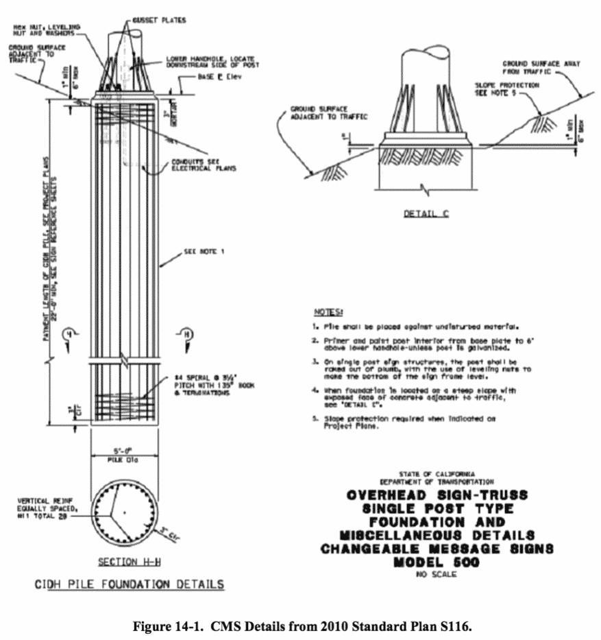
Overhead Sign Structures (OHS) are overhead signs attached to a steel truss that are typically supported by a combination of a single post with a large diameter Cast-In- Drilled-Hole (CIDH) pile foundation. Figure 14-1 shows a 5-foot diameter pile with a minimum length of 22 feet for Changeable Message Sign (CMS) Model 500.
Construction of an OHS foundation is difficult when groundwater is encountered. If there is groundwater, then the slurry displacement method is usually required as described in Chapter 9, Slurry Displacement Piles.
The contract specifications outline all the requirements. However, plans for CIDH piles for OHS foundations are found in the 2010 Standard Plans. These plans do not show the location of the PVC inspection pipes, which means the pile reinforcement cage requires reconfiguration to accommodate the inspection pipes in accordance with the requirements of Bridge Memo to Designers 3-1, Attachment 2, when the slurry displacement method is used.
Another consideration is the presence of the signpost anchor bolts. The anchorage system is typically heavy and must be positioned precisely to accommodate the signpost. This is further complicated if the foundation pile is constructed using the slurry displacement method. Use of the permissible construction joint shown on the OHS foundation plan sheet should be encouraged when the pile is constructed using the slurry displacement method, which allows the signpost anchorage system to be placed after the pile concrete is placed below the construction joint. Structure Representatives are advised to consider all of these factors during review of the Contractor’s pile installation plan.
Contractors that are smaller operations or inexperienced typically have difficulty meeting slurry displacement method submittal and construction requirements. Structure Representatives need to thoroughly communicate all requirements. The CIDH pile preconstruction meeting is a good forum to initially discuss slurry displacement method requirements.
A Log of Test Borings (LOTB) might not be included in small OHS projects, making it difficult to anticipate the presence of groundwater, indicating no foundation investigation was performed. If this is the case, corrosion information might not be available for corrosion evaluation of an anomalous pile. A proactive Structure Representative can obtain LOTB as-built drawings from the nearest bridge structure location. The proactive Structure Representative should review the LOTB as-built drawings and share the information with the Contractor. As-built drawings are available at District Headquarters and online on the Intranet [Bridge Inspection Records Information System (BIRIS) and Document Retrieving System (DRS)].
Personnel safety must be enforced during drilling and excavating operations. A full-body harness should be used when working near open holes. In order to avoid falling in or collapsing edges, personnel not directly involved in the construction operation should not stand next to an open hole.
14-3.2 Tip Grouting
Tip grouting is a procedure used to enhance the end bearing capacity of a CIDH pile. The CIDH pile is constructed with a grout delivery system installed at the base of the pile reinforcement cage. Upon completion of pile concrete placement and cure, grout is pumped through the grout delivery system to consolidate the foundation material at the tip of the CIDH pile, which, in theory, enhances the end bearing capacity of the pile.
An advantage of tip grouting includes the ability to shorten CIDH piles considerably from the length that would be required considering only “skin friction” capacity of the pile. This reduction in length can be substantial and result in considerable cost savings to the project.
A disadvantage of tip grouting includes the inability to properly assess the actual end bearing capacity of the CIDH pile after tip grouting is completed without performing a static load test. There is no known methodology of calculating the enhancement of end bearing capacity using only grout pressures and grout volumes placed.
Caltrans’ position on tip grouting is that it is not authorized for use on state highway projects. However, tip grouting has been utilized on a design-build project sponsored by a local agency. Results have been tabulated and lessons have been learned from this project, but there has been no conclusive evidence presented to date that tip grouting resulted in the piles meeting the required design capacity. Due to the potential for cost reduction, Caltrans continues to investigate tip grouting and it may be authorized for use on state highway projects in the future.
14-3.3 Type II Shafts
Foundations that use a single pile to support a column are designated as Type I or Type II shafts. A Type I shaft utilizes a single bar reinforcement cage for the pile and the column. A Type II shaft utilizes a bar reinforcement cage for the pile and one or more separate reinforcement cages for the column.
For a Type II shaft constructed using the slurry displacement method, the special consideration occurs at the tip of the column reinforcement cage(s). A construction joint is required at this location. The construction joint is a constructability enhancement designed to allow concrete to be placed in the area of pile and column reinforcement cage overlap by the dry method. However, there are several factors that must be considered at the construction, which include the following:
- Since the location of the construction joint is typically below grade, a permanent casing suitable for worker entry is required, from the ground surface to 5 feet (2-feet if the casing is embedded in bedrock) below the level of the construction joint.
- The pile concrete must be placed, acceptance testing performed, and any mitigation completed before column construction begins.
- Any pile concrete that is wasted above the level of the construction joint as described in Chapter 9, Slurry Displacement Piles, must be removed to at least the location of the construction joint before column construction begins.
Structure Representatives are advised to review the project documents for the presence of Type II shafts, engage in discussions with the Designer and Contractor about design considerations and construction methods, and thoroughly vet the Pile Installation Plan before authorizing it.
Additional safety concerns with Type II shafts include the presence of an open hole for a longer period of time than with ordinary CIDH piles and that workers must enter the hole to prepare the construction joint for column construction. Fall protection and confined space safety procedures must be followed, and if the level of the construction joint is far enough below the ground surface, CalOSHA Mining and Tunneling Safety Orders may apply. Structure Representatives must ensure the Contractor has an authorized safety plan addressing these concerns – and adheres to it.
14-3.4 Soldier Piling
Soldier Piling consists of a heavy rolled structural steel shape placed in a drilled hole, which is then filled with concrete. Soldier Piles are typically used for temporary shoring and permanent earth retaining structures. Requirements for Soldier Piling are found in the 2010 Standard Specifications1.
One of the special considerations for soldier piling is the drilled hole must be dry when concrete is placed. Those of you who have built soldier piling know that this is not always the case. Tremie seals and temporary casings may be required, which can be difficult to maneuver in locations where soldier piling are typically used. Dewatering the drilled hole can also be problematic. Prudent Structure Representatives discuss the possibility of wet holes and how they will be handled with the Contractor – prior to the start of soldier pile construction.
Another special consideration for soldier piling is the specification requirement that the drilled hole have 1-inch minimum clearance to the steel piling. Typically this means the Contractor will try to drill the smallest diameter hole possible. Structure Representatives are advised to discuss the size, location, and plumbness of the drilled hole and soldier pile alignment requirements with the Contractor – prior to the start of soldier pile construction.
-
 SPW911 Sheet Pile Design Software
Rated 5.00 out of 5$150.00 – $599.99Price range: $150.00 through $599.99
 -
 Sheet Pile Design (PDF Download)
Rated 5.00 out of 5$89.00
 -
 Pile Driving (PDF Download)
$89.00
-
 Marine Construction Volumes 1 & 2 (PDF Download)
$157.00
-
 Pile Driving (Book)
$89.00


