Chapter 12 – Cofferdams and Seal Courses
- Chapter 1 – Foundation Investigations
- Chapter 4 – Footing Foundations
- Chapter 5 – Pile Foundations
- Chapter 6 – Cast-In-Drilled-Hole Piles
- Chapter 7 – Driven Piles
- Chapter 8 – Static Pile Load Testing and Pile Dynamic Analysis
- Chapter 9 – Slurry Displacement Piles
- Chapter 11 – Ground Anchors & Soil Nails
- Chapter 12 – Cofferdams and Seal Courses
- Chapter 14 – Specialty Piles and Special Considerations for Pile Foundations
Foundations Manual by Caltrans
12-1 General
A cofferdam is a retaining structure, usually temporary in nature, which is used to retain water and support the sides of excavations where water is present. These structures generally consist of: (1) vertical sheet piling, (2) a bracing system composed of wales, struts, or tiebacks, and (3) a bottom seal course to keep water from piping up into the excavation or to prevent heave in the soil. Cofferdams differ from braced excavations or shoring in that they are designed to control the intrusion of water from a waterway and/or the ground.
A seal course is a concrete slab poured under tremie to block the intrusion of water into the bottom of an excavation. The limits of the cofferdam are the limits of the seal course and the thickness is calculated to address engineering considerations such as pressures from differential hydrostatic head at the bottom of footing elevation.
12-2 Sheet Piles and Bracing
There are three basic materials used for the construction of sheet piles: wood, concrete, and steel. Wood sheet piling can consist of a single line of boards or “single-sheet piling” (Figure 12-1), but it is suitable for only comparatively small excavations where there is no serious ground water problem.
In saturated soils, particularly in sands and gravels, it is necessary to use a more elaborate form of sheet piling which can be made reasonably watertight with overlapping boards spiked or bolted together, such as the “lapped-sheet piling” or “Wakefield” system (Figure 12-2).
“Tongue and groove” sheet piling (Figure 12-3) is also used. This is made from a single piece of timber that is cut at the mill with a tongue and groove shape.
Precast concrete sheet piles (Figure 12-4) are normally used in situations where these members are going to be incorporated into the final structure or are going to remain in place after they fulfill their purpose. Caltrans does not normally encounter precast concrete sheet piling in structure work. However, it is usually made in the form of a tongue and groove section. They vary in width from 18 to 24 inches and in thickness from 8 to 24 inches. They are reinforced with vertical reinforcing steel bars and hoops in much the same way that is done with precast concrete bearing piles. This type of sheeting is not perfectly watertight; however the spaces between the piles can be grouted to try to address this.
 In order to provide a more watertight precast concrete sheet pile, two halves of a straight steel web sheet pile, which has been split in half longitudinally, are cast into the concrete pile during fabrication (Figure 12-5).

Steel sheet piling is most commonly used in the field. It is available in a number of different sizes and shapes. The shape provides bending strength and each end is fabricated with an interlock (connection between sheets) that provides alignment and interconnectivity between sheets. Each steel company that manufactures sheet piling has its own shape and form of interlock. The simplest shape is known as the “straight-web” (Figure 12-6). These are made in various widths ranging from about 15 to 20 inches. The web thickness varies from about 3/8 to 1/2 inch. The straight-web sheet piling is comparatively flexible and it requires a considerable amount of bracing in deeper excavations where lateral loads from waterways and soils are large.
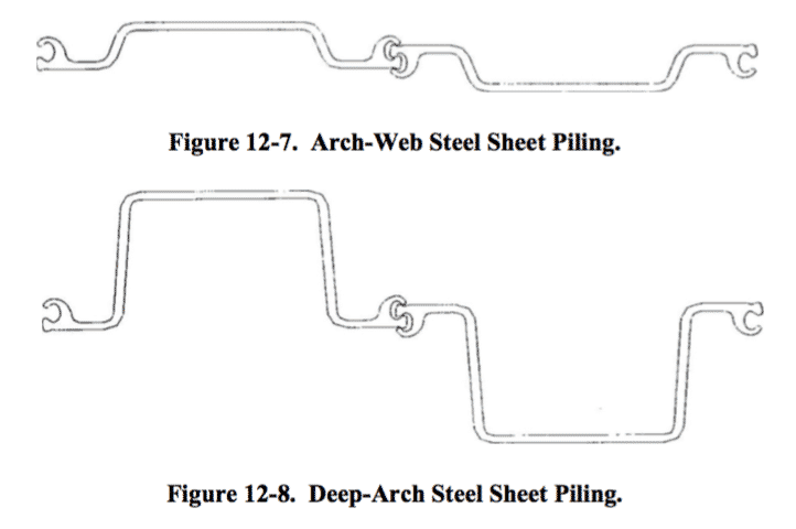
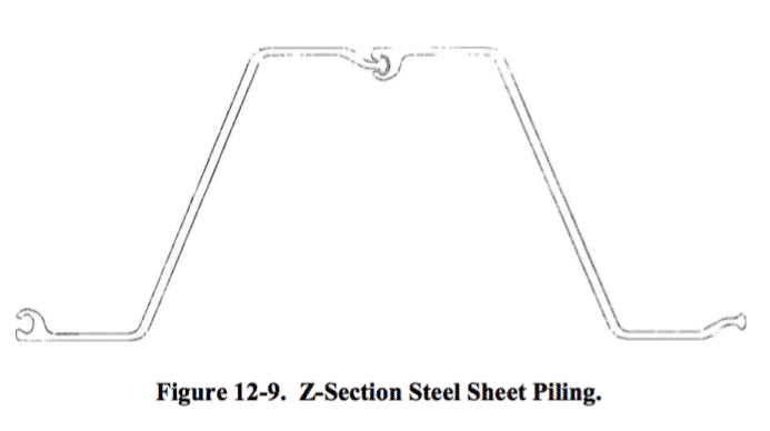
In order to provide greater resistance to bending, the steel companies have developed sheet piles in a variety of shapes. One type is known as the “arch-web” section (Figure 12-7), where the center of the sheet is offset to provide a greater moment of inertia in the cross section. A “deep-arch” section (Figure 12-8) provides an even greater stiffness. It is similar to the “arch-web” except that the offset in the web is considerably larger. A third type, known as the “Z-Section” (Figure 12-9) has considerably greater stiffness than that of the “deep-arch” and is used in deeper excavations.
The choice of the type of steel sheet pile to be used on a given project depends largely on the kind of service in which it will be used. The straight-web is comparatively flexible so it requires a considerable amount of bracing to resist large lateral loads in excavations. However, its cross section allows it to be used in locations where space is an issue and where a deep-arch or Z-Section will not fit in between the excavation limits and an obstruction or Right-of-Way line.
The composition of the bracing system inside the cofferdam will depend upon the forces that system must resist, the availability of materials, and the costs connected with the system. Ground anchors can be used in large land cofferdams where a system of cross bracing is impractical.
12-3 Excavation
Cofferdams in waterways are typically excavated with a submerged clamshell bucket, with the excavation elevations being checked by sounding. In the case of pile foundations, it is often advisable to over-excavate a predetermined amount to compensate for possible heave of the foundation material caused by driving piles; displacement piles in particular. This is done to eliminate the need for excavation after driving. If excavation is needed, care needs to be taken so as not to damage any of the driven piles.
To ensure the stability of the excavation, a seal course is used to control the influx of water into the excavation from the bottom due to hydrostatic head differentials. The contract plans show where seal courses are required. As in many other areas of our work, there are times when engineering judgment should be used to make decisions. Depending on the types of soils and the depth of the excavation in relation to that of the water table, the cofferdam may be dewatered without constructing a seal course while still allowing construction of the footing in the dry. The decision to use a seal course that is shown on the contract plans, or to revise its thickness, is the responsibility of the Engineer. Discussions about the need for a seal course or revisions to thickness need to take place early so that design considerations for the cofferdam can be addressed.
Seal courses for cofferdams might not be shown on the contract plans but may be needed to facilitate construction and provide a quality product. If a seal course is not shown on the contract plans and the Contractor elects to use one to control and remove water from the excavation, the work must be done in accordance with the provisions of the contract specifications1.
12-4 Seal Course
The contract specifications2 state that a seal course should be used when the Engineer determines it is impossible or inadvisable to dewater an excavation prior to pouring concrete. As the name implies, a seal course seals the entire bottom of a cofferdam and prevents subsurface water from entering the cofferdam. It also controls the expansion of soils that have a tendency to expand or heave. Sealing the bottom of the cofferdam allows cofferdams to be dewatered and permits the construction of footings, columns or other facilities in the dry. The seal course is a concrete slab placed underwater by the tremie placement method and is constructed thick enough so that its weight is sufficient to resist uplift from hydrostatic forces. The friction bond between the seal course concrete, the cofferdam, and piles if present, also helps resist uplift. A seal course is a construction tool and in terms of importance to the designed structure it has no structural significance.
Following the installation of the cofferdam and prior to dewatering, the soil is excavated to the elevation of the bottom of the seal course, and the piles are driven. The seal course is poured under tremie and allowed to cure. The cofferdam is dewatered after the seal course has cured. A small area of the seal course can be left low for the placement of a pump to remove water that seeps into the excavation prior to the placement of footing concrete.
Information about seal courses for a project can be found in the contract plans. Additional information may be found in the Foundation Report or RE Pending File. As previously discussed, when seal courses are shown on the contract plans, the decision about the need for the seal course and its thickness rests with the Engineer. This decision is based on conditions encountered on the jobsite. The contract specifications3 also contain provisions for adjusting excavation item quantities if seal courses are adjusted or eliminated. Additional information about seal courses can be found in Bridge Construction Memo 130-22.0, Seal Courses. Bottom of footing elevations should not be revised as a result of eliminating or revising seal courses unless shown on the contract plans or addressed in the special provisions.
-
 SPW911 Sheet Pile Design Software
Rated 5.00 out of 5$150.00 – $599.99Price range: $150.00 through $599.99
 -
 Sheet Pile Design (PDF Download)
Rated 5.00 out of 5$89.00
 -
 Pile Driving (PDF Download)
$89.00
-
 Marine Construction Volumes 1 & 2 (PDF Download)
$157.00
-
 Pile Driving (Book)
$89.00


