Chapter 1 – Foundation Investigations
- Chapter 1 – Foundation Investigations
- Chapter 4 – Footing Foundations
- Chapter 5 – Pile Foundations
- Chapter 6 – Cast-In-Drilled-Hole Piles
- Chapter 7 – Driven Piles
- Chapter 8 – Static Pile Load Testing and Pile Dynamic Analysis
- Chapter 9 – Slurry Displacement Piles
- Chapter 11 – Ground Anchors & Soil Nails
- Chapter 12 – Cofferdams and Seal Courses
- Chapter 14 – Specialty Piles and Special Considerations for Pile Foundations
Foundations Manual by Caltrans
1-3 Foundation Investigation Overview
At the beginning of a design project for a new structure, widening, strengthening, or seismic retrofit, the Designer submits a Foundation Investigation Request to the appropriate Geotechnical Design Section. From this request, a Geoprofessional is assigned to perform the foundation investigation.
The assigned Geoprofessional performs a foundation investigation by first collecting as much information as possible about the proposed site. This includes reviewing preliminary structure plans, previously written foundation reports, as-built plans, the area’s historical seismicity information, and historical subsurface conditions. This planning phase of the investigation gives the Geoprofessional an idea of what to watch for during fieldwork.
A drilling plan is important to make efficient use of the available drilling equipment and personnel. Once all preliminary subsurface information from the site is collected, the drilling plan is generated to outline locations for drilling relative to the structure’s proposed foundation. The Geoprofessional directs the foundation drilling crew during the subsurface drilling operation (described later in this chapter) as they collect soil samples and perform in situ testing at the site.
Information necessary to develop the project’s LOTB includes: soil samples collected during the subsurface drilling operation, results of in situ tests, manual field tests, and various recorded observations. Once the LOTB is completed, it is transmitted to the Designer and is included in the structure plans.
The Geoprofessionals in Geotechnical Services analyze information compiled in the LOTB, along with the loads provided by Structure Design, and make foundation recommendations. The recommended foundation type and other important information is included in the Foundation Report, and transmitted to the Designer. These recommendations are used to complete the structure design. The Foundation Report is included in the RE Pending File and the Supplemental Project Information handout for the contractor at time of bid.
1-4 Subsurface Drilling Operation
Results obtained from the subsurface drilling operation are the most important aspects of a foundation investigation. Foundation drilling crews conduct one or more drilling operations at the structure’s proposed location. The subsurface investigation helps determine the depth of rock, rock type and quality, soil types, soil strengths, and groundwater levels. Determining these parameters enables development of a soil/rock profile, which is a visual representation of the subsurface conditions interpreted during subsurface investigations and laboratory testing. The soil/rock profile can be determined by interpolating between comparable lenses of material in individual borings within the LOTB.
The appearance and feel of the cuttings, difficulties or changes in the rate of drilling tool advancement, and other observations help estimate the mechanical properties or strengths of the soil or rock lenses. These observations are noted within field logs. Any groundwater encountered during the drilling operation also is noted, and special care is taken to accurately determine its elevation and whether the groundwater encountered is static or under pressure (“perched” or in an “artesian” condition). These observations, along with the results from field and laboratory testing, are used to develop the soil/rock profile.
Two important facets of the subsurface drilling operation are the recovery of soil samples retrieved during drilling operations and the in situ soil tests. Soil samples are divided into two categories: disturbed and undisturbed. Disturbed soil samples are those that have experienced large structural disturbances during the sampling operation and may be used for identification and classification tests. Undisturbed samples are those in which structural disturbance is kept to a minimum during the sampling process. Undisturbed samples are used for consolidation and strength tests. Examples of these strength tests are direct shear, triaxial shear, and unconfined compression tests. The strength tests provide shear strength values, which are then used as design parameters in static analysis for pile foundations. Consolidation tests provide information needed to estimate settlements of spread footings or pile groups, and are performed on cohesive soils.
Several types of soil samplers are used to retrieve undisturbed samples during subsurface investigations. Types include the California Sampler (which is the primary tool used by Geotechnical Services), the Shelby Tube, the Piston Sampler, and the Hydraulic Piston Sampler. Undisturbed soil samples provide the best opportunity to evaluate the soil in its natural, undisturbed state. Destructive testing of these samples provides the most accurate soil data; however, undisturbed samples from non-cohesive, or cohesionless soils are difficult to obtain, trim, and test in the laboratory. Soft, saturated clays; saturated sands; and intermixed deposits of soil and gravel are difficult to sample and test in the laboratory. To overcome these difficulties, in situ test methods are used to measure soil parameters.
When standard drilling and sampling methods cannot be used to obtain high-quality, undisturbed samples, in situ tests are used to provide information about the material characteristics. The most common of these tests is the Standard Penetration Test (SPT). This test identifies a penetration resistance value, “N,” which can be used to obtain estimates for the angle of internal friction of a cohesionless soil, the unconfined compressive strength of a cohesive soil, and the material’s unit weight (refer to Appendix C). The SPT is performed using a split-spoon sampler and provides a disturbed sample for visual inspection and classification. Other in situ tests include the static cone test, pressure meter test, vane shear test, and the borehole shear test. They provide soil strength values such as cohesion, angle of internal friction, and shear strength.
Design parameters obtained from field and laboratory testing are used for static analytical design procedures, pile and footing foundations. They may also provide valuable information to the Engineer during the course of administering a construction project.
1-5 Log of Test Borings
After the subsurface investigation and laboratory testing is complete, the project’s LOTB is developed. The LOTB includes a plan view showing the location of each boring retrieved during the subsurface drilling operation. It provides a graphic description of the various layers of geological formations, soils, and the location of the groundwater table (if encountered). Various soil and rock properties also are described. Each LOTB includes a standard legend on the left side of the sheet that describes the different symbols and notations used within the LOTB. Examples of LOTB are included in the Caltrans Soil and Rock Logging, Classification, and Presentation Manual provided in Appendix A. It also can be found on the SC website3.
1-6 Foundation Report
The Foundation Report contains all information retrieved during the foundation investigation, and provides the Designer with a description and evaluation of the geological formations and soils at the proposed project site. It also describes and evaluates any seismic hazards that may be present, such as the anticipated amount of ground shaking and probability of liquefaction at the site. The report gives recommendations for:
-
- The type of foundation to be used to support the proposed structure.
- Seismic design criteria, such as peak horizontal bedrock acceleration to be used in the seismic analysis.
- Recommendations for bottom of footing elevations, pile type, and size and tip elevations.
Most reports include special comments about anticipated foundation-related concerns during construction such as caving, soil compaction problems, expected variations in pile driving, and potential problems due to groundwater. This section of the report may even suggest that job-specific specifications be included in the contract’s special provisions. The Structure Representative should pay particular attention to these comments as advance knowledge of potential foundation problems allows for more effective problem- solving and mitigation. The Foundation Report normally is included in the RE Pending File and is included in the Supplemental Project Information handout available to the Contractor at time of bid. If the Structure Representative did not receive a copy of the Foundation Report for a specific project, he or she should contact the SC Headquarters Office to request one.
The Structure Representative should review the project plans to verify that the footing elevation, pile tip elevations, and type of piling recommended in the Foundation Report are shown on the contract plans. In addition, the Structure Representative should confirm that any suggested specifications or design features mentioned within the special comments section of the Foundation Report are included in the contract plans and specifications. Consult with the Designer and Geoprofessional if there are any discrepancies. Contract change orders most likely will be required to address these discrepancies.
Constructability issues discussed in the Foundation Report should be discussed with the Contractor as early as possible. Once the Contractor begins work, the Structure Representative should observe and note how the Contractor makes preparations to deal with the constructability issues discussed in the Foundation Report. Detailed and thorough documentation of all conversations with the Contractor about these issues will be of important if any claims are submitted by the Contractor.
1-7 Applicability of the Log of Test Borings (LOTB) and Foundation Report to the Contract
It is very important for Structure Representatives and all SC field staff to be aware of how the contract specifications describe the applicability of the LOTB, the Foundation Report, or any record of subsurface investigation produced by Caltrans. The contract specifications4 describe the Contractor’s responsibilities for reviewing these documents prior to performing work for Caltrans.
In the past, the LOTB and other information provided to the Contractor at the time of bid were not considered part of the contract and were provided for information only. The 2006 Standard Specifications4 states that the Contractor is required to investigate the site, and includes other available information. Information provided by Caltrans will be used by the Contractor to develop a competitive bid. Therefore, the accuracy of this information is essential for a claim-free contract. Even though Caltrans takes responsibility for the information that is provided, the Contractor still is required to carefully examine the site and the Caltrans-provided information, and is responsible for conclusions they draw from that investigation. The 2010 Standard Specifications4 simplifies this by requiring the Contractor to “Examine the job site and Bid Documents.” The LOTB and the Foundation Report are included within the Bid Documents as the Supplemental Project Information handout.
1-8 Basic Soil Properties
Geotechnical Services recently published the Caltrans Soil and Rock Logging, Classification, and Presentation Manual (Appendix A). It contains information about the field and laboratory procedures used in soil classification and descriptions. It will help the Engineer clearly understand and interpret information presented in the LOTB and the Foundation Report, and facilitate communication with Geotechnical Services.
The information presented in Chapter 2 of the Caltrans Soil and Rock Logging, Classification, and Presentation Manual (Appendix A) is particularly important as it outlines procedure and methodology to identify and classify rock and soil samples. Information presented in the logs and descriptions is based on the ASTM D 2488-06 Standard Practice for Description and Identification of Soils (Visual-Manual Procedure) and the Engineering Geology Field Manual published by the Bureau of Reclamation.
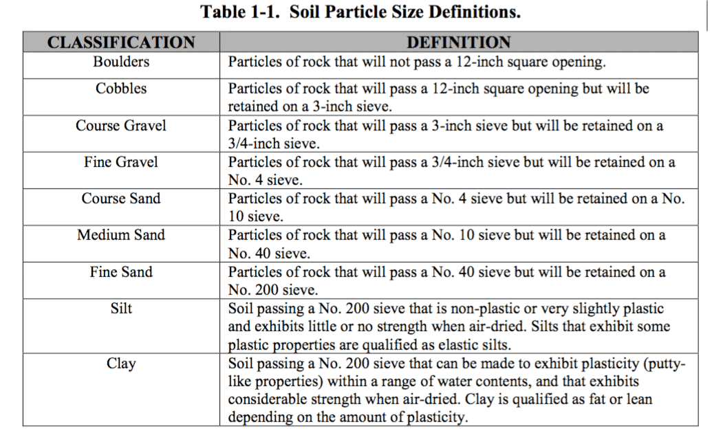
Table 1-1 lists soil particle size definitions used by Geotechnical Services:
Geoprofessionals provide descriptive components and describe soils by name and group symbol to complete the identification. Some descriptive components such as consistency, apparent density, and percent or proportion of soils are mandatory while others, such as particle shape, are not. Refer to Figure 2-5 Identification and Description Sequence of the Caltrans Soil and Rock Logging, Classification, and Presentation Manual for a complete list of descriptive components (Appendix A). An example of a complete descriptive sequence for a sample is:
Well-graded SAND with GRAVEL (SW), medium dense, brown to light gray, wet, about 20% coarse subrounded to rounded flat and elongated GRAVEL, about 75% coarse to fine rounded SAND, about 5% fines, weak cementation.
Visual inspection generally is sufficient to differentiate between the coarse-grained soils. However, distinctions between soil particles such as silts and clays can be difficult.
Several simple field exercises using settling measures, plasticity, dry strength, and permeability characteristics of the soil result in more accurate soil classifications. Soil samples also can be taken to the laboratory and tested to determine plasticity, unit weight, unconfined compressive strengths, and other mechanical properties to refine field classification. Alternatively, the following tests can be used to help classify soils in the field:
- Water dispersion: Once a soil is dispersed in water, sand grains settle rapidly – usually in less than one minute. Silt settles more slowly, usually from 10 to 60 minutes. Clay will remain in suspension for several hours.
- Plastic thread formation: Sand, having little to no plasticity, will not form a plastic thread by rolling it on a smooth surface. Silt will form a thread when rolled, but it is weak and crumbles as it dries. Clay forms a plastic thread of high strength, which dries slowly and usually becomes stiff and tough as it dries.
- Dry strength: Sand has no unconfined dry strength. Silt has very little dry strength and easily powders when rubbed. Clay has a high dry strength and will not powder easily.
- Shaking or patting: A rough indication of the plasticity (clay content) of a soil can be determined by observing a sample’s reaction to shaking or patting. For example, when a sample of silt is subjected to this type of movement, water appears on the surface. However, when shaking or patting a sample of clay soil, this reaction occurs slowly or not at all due to the level of the sample’s plasticity.1-9 Geotechnical Drilling and Sampling EquipmentMany different tools are used by foundation drilling crews and Geoprofessionals to obtain samples and evaluate subsurface conditions.The SC employees must have a good working knowledge of the equipment used during the subsurface drilling operation for their projects. Different tools used to perform a drilling operation have different levels of reliability. Reliability of the tool used during a subsurface investigation is an important factor in determining the accuracy of information provided in the Foundation Report.
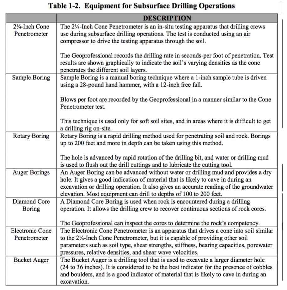
Table 1-2 describes equipment used by Geotechnical Services and consultant geotechnical companies.
-
 SPW911 Sheet Pile Design Software
Rated 5.00 out of 5$150.00 – $599.99Price range: $150.00 through $599.99
 -
 Sheet Pile Design (PDF Download)
Rated 5.00 out of 5$89.00
 -
 Pile Driving (PDF Download)
$89.00
-
 Marine Construction Volumes 1 & 2 (PDF Download)
$157.00
-
 Pile Driving (Book)
$89.00


