Hoisting & Rigging – Part II: Hardware and Hoists

Proper utilization and inspection of shackles, eyebolts, hooks, and clips is of high importance when moving sizable loads. The following article provides operating guidelines and inspection-related overviews of these common rigging components, along with a review of hoists and general terminology.
Shackles
Manufactured in anchor and chain configurations for rigging use, shackles are available with screw pins, round pins, or safety bolts.
Anchor shackles have a rounded eye, making them suitable for attaching one or more hooks or slings. Featuring a straight eye, chain shackles are designed for connection to a single lifting device. Each shackle body should be marked with an identifying manufacturer’s name or shackle size, which is determined by the diameter of its bow or body.
Prior to conducting lifting, an operator should inspect shackles to ensure that the pin is completely seated, pin threads are not exposed, and the shackle itself shows no signs of deformation. If the pin can’t be completely seated, the shackle should not be used. If the pin can roll under a load and unscrew, in the case of a screw pin shackle, it also must not be used.
When replacing a shackle pin, never use a bolt, as they’re not intended to take the bending that is typically applied to the pin. Only a properly fitted pin should be used. Once replaced, the shackle pin should go on a hook whenever possible. If needed, washers may be used to pack the pin in order to centralize the shackle. Once in operation, shackles should never be pulled at an angle, as eccentric loading may cause them to open or distort.

Eyebolts
Available as shouldered or unshouldered, eyebolts firmly attach a securing eye to a structure and feature self-locking nuts. The minimum thread engagement between an eyebolt and its tapped hold should be 1.5 times the diameter of the thread engagement.
Used for vertical and angular lifts, shouldered eyebolts are found in many applications. When utilized for angular lifts, the safe working load must be down rated, with lifting angles of less than 45 degrees being prohibited. Unshouldered eyebolts are used for vertical lifts only, as angular lifts would bend the threaded shaft.
When eyebolts cannot be properly seated, washers or shims may be inserted under the shoulders; however, minimum thread engagement must be maintained.
Angular loading of eyebolts should be avoided. This occurs in any lift where the lifting force is applied at an angle to the centerline of the shank of the eyebolt. Again, lifting angles of less than 45 degrees are prohibited. Spreader bars, lifting yokes, or lifting beams should be utilized to eliminate angular loading when more than one eyebolt is used in conjunction with multiple-leg rigging.
To keep bending forces on an eyebolt to a minimum, a load should always be applied in the plane of the eye rather than in the other direction. If a hook will go completely into an eyebolt, a shackle should be used to avoid hook tip loading.
Lastly, slings should not be reeved through a single or pair of eyebolts, as doing so adds greater load tension in the eyebolt.
When inspecting eyebolts prior to use, ensure the shank has a smooth radius into the plane of the shoulder and is not undercut. Any eyebolt that is cracked, bent, or has damaged threads must be discarded.
Hooks
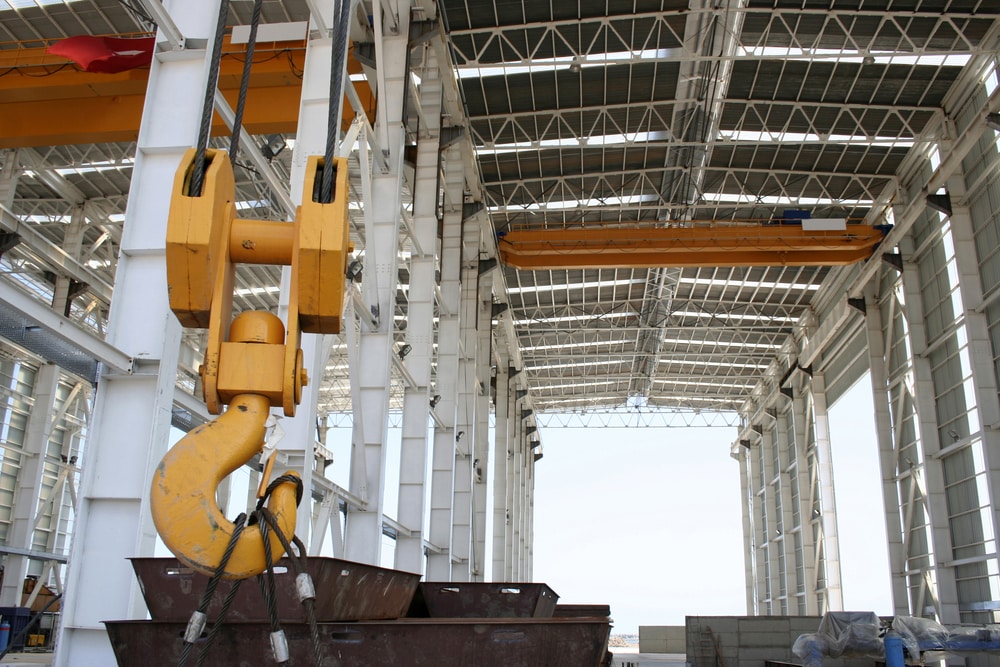
Load hooks are generally the weakest member of lifting equipment, bending if overloaded before any other piece of equipment fails. The safe working load for a rigging hook should be higher than the rated load of the chain wire rope or other suspension member to which it is attached to avoid bending.
It is common practice to use a shackle when two or more sling eyes are used on a hook. This allows the load to be centralized on the hook for full capacity. Hooks should also be provided with a safety latch to bridge the throat opening, which itself prevents the release of load lines.
Hook tips should point out and away from the load to assure that, when slack is taken up, the hook will not tip load. Additionally, hands, fingers, and other body parts should be kept from between the hook and load.
Prior to use, the operator must look for bending or twisting that exceeds 10 degrees from the plane of the unbent hook while also checking for wear in the saddle area of the hook. Wear exceeding 10 percent of the original dimension warrants taking the hook out of service.
If an increase in throat opening exceeds 15 percent of the original throat opening, the hook must also be taken out of use. Most hooks feature punch marks as reference points.
Cracks, severe nicks, and gouges can also eliminate hooks from service. Note that transverse cracks are more critical to a hook’s performance than longitudinal cracks.

Wire Rope Clips
Used to make an eye on wire rope, U-bolt, fist grip, and collet connection clips may never be reused, as they may not torque properly on second application. All clips utilized in the field should be legibly and permanently marked with size and their manufacturer’s identifying mark.
When installing clips, apply the first clip one base width from the dead end of the wire rope, tightening nuts evenly to the recommended torque. Next, apply the second clip as near the loop as possible and then the U-bolt over the dead-end. Turn nuts firmly, but do not tighten. Apply the remaining clips equally between the first two, before tightening all nuts to the recommended torque. When using single grip clips, place the saddle on the live end of the rope. Always recheck torque after use of any clips.
Clips should not be used to fabricate wire rope slings except where application prevents the use of prefabricated slings. In these situations, the clips must be proof tested to 200 percent of the safe working load.
Before use, clips should be visually inspected for damage, corrosion, wear, and cracks. The operator or person in charge must also verify that the assembled clip contains the correct size, type, and class parts.
Rings
Weldless, forged steel rings are standard in lifting operations. Welded rings are not recommended unless designed by a qualified engineer and subjected to testing. All rings must be visually inspected for corrosion, wear, cracks, twists, and openings prior to use.
Turnbuckles
Turnbuckles are rarely used in a rigging system. Those that are should be fabricated from forged alloy steel. If used in an application where vibration is present, the turnbuckle’s end fitting must be secured to the frame with lock pins or wires in order to prevent them from turning or loosening. Locknuts must not be used, as they increase the level of stress imposed upon the threads.
Before use in lifting, turnbuckles should be inspected for thread damage, as well as cracks and bends in the frame. The appearance of these deficiencies disqualifies a unit from use.
Load Measuring Devices
Used to measure loads under stress, these devices are needed with lifts where the biding or friction of the load could result in a greater stress on the hoist or tackle. These devices are also utilized when loads slated for lifting are more than 90 percent of the rated capacity of the equipment being used, or in situations where the load can’t be weighed or verified.
The load indicating system should include a means for the operator to determine that it is operational before crane use. The read-out device should be placed in a location where the operator can obtain readings from their normal working position.

Hoists
Available as electric, air, or hand powered types, hoists are not permanently mounted and are always allowed to hang freely.
Both electric and air powered hoists are pendant operated, with controls returning to the off positions when released and when motion stops. Pendant control components include power cable, pendant support, hoist drum, hoist line, limit switch actuator, block, hook, sling, safety latch, and I-beam.
Hand chain operated hoists are manually powered, and designed to automatically stop and hold a load when lifting force is removed. Chain hoists should be rigged so that a straight line between the upper and lower hooks exists. These hoists are intended for use only in a vertical or near vertical position. If rigged at an angle, the upper hook can be damaged at the shank and the throat may open. If the gear housing rests against an object while under load, it can be damaged or broken.
In general, hoists feature four basic components: bottom (load) block, drum, limit switches, and pendant station.
The bottom block is the assembly of hook, shackle, swivel, bearing, sheaves, pins, and frame as suspended from hoisting ropes or chains. A cylindrical, flanged barrel on which rope is wound, the drum may be smooth or grooved.
Upper and lower limit switches are tasked with restricting the raising and lowering capabilities of the hoist through altering of the electrical circuit. The upper switch restricts the upward travel of the hoist based on the revolutions of the drum or when the block contacts a device below the hoist drum. Lower switches reduce the downward travel of the hoist in a similar fashion. When no lower switch is utilized, no less than two full wraps of rope should remain on the hoist drum when the hook is in a fully-extended position.
The pendant station is comprised of controls suspended from the hoist. These controls are used to operate the hoist unit from the ground.

Overhead Traveling Cranes
Large cranes utilized in lifting operations are mostly of the overhead type, these being controlled by a pendant that hangs from the crane. The pendant controls the hoist motion and bridge, along with trolley travel.
While types of overhead traveling cranes vary, each features three basic components: runway, bridge, and trolley.
Resembling a railroad truck, the runway is comprised of rails, beams, girders, and brackets that provide the framework and support for the crane. Traveling on the runway, the bridge is made up of two or more girders, trucks, and a drive mechanism that moves the bridge along. The trolley is carried by the bridge, moving horizontally between the runways and providing support for the hoist mechanism, which consists of the load block.
Wire ropes connected to a motor-driven drum and threaded through the load block are used to raise and lower the load. As the load is raised to the end of the load block travel, it meets a limit switch actuator, which stops the travel of the block and prevents the crane from being damaged and the load from being dropped.
All overhead cranes must be inspected monthly by maintenance, with the procedure noted on the inspection tag.
How should shackles be inspected for safe rigging operations?
Operators should inspect shackles before lifting to ensure the pin is fully seated, pin threads are covered, and there are no signs of deformation, avoiding use if the pin can't be seated or can roll under a load.
What are the key considerations for inspecting load hooks in lifting equipment?
Before use, operators must check load hooks for bending, twisting, wear in the saddle area, and any signs of cracks, with wear exceeding 10% warranting removal, and any increase in throat opening beyond 15% disqualifying the hook from use.

