


Thermal Integrity Profiling (TIP) vs CSL Testing for Drilled Shafts
Drilled shaft integrity testing is an essential part of drilled shaft QA/QC for bridges, transmission structures, marine facilities, commercial foundations, and other critical infrastructure. For DOT engineers, contractors, geotechnical consultants, and quality managers, the decision between Thermal Integrity Profiling and Crosshole Sonic Logging affects instrumentation planning, construction sequencing, testing coverage, data timing, and the type of information available for drilled shaft integrity evaluation. TIP testing and CSL are both non-destructive methods, but they use different physical principles and should not be treated as interchangeable without considering project requirements.
Understanding Drilled Shaft Integrity Testing
Drilled shaft integrity testing is used to evaluate whether the completed concrete shaft appears consistent with the intended construction and whether the results indicate conditions that require additional engineering review. Testing does not replace sound drilling practices, concrete placement procedures, slurry control, excavation inspection, reinforcement cage installation, or detailed construction records. Instead, it gives project teams another source of information for evaluating the completed foundation.
Conditions that may require review can include potential necking, soil intrusion, poor-quality concrete, segregation, unexpected geometry changes, cage eccentricity, or other irregularities. The cause and structural significance of an indication cannot be determined from one data point alone. Engineers typically review testing data alongside concrete volume records, slurry reports, drilling logs, tremie placement records, cage elevation information, design assumptions, and site observations.
Why Integrity Testing Matters
Drilled shafts are often installed below grade in conditions where direct visual inspection of the completed concrete is not possible. Once the concrete is placed, the project team needs reliable methods to assess whether the shaft appears consistent with the expected geometry and concrete quality.
This is especially important for projects involving bridge piers, elevated roadways, transmission structures, marine terminals, retaining systems, and heavily loaded commercial facilities. An unresolved drilled shaft concern can affect production schedules, acceptance decisions, remediation planning, and the sequencing of follow-on work.
Selecting a Method Before Construction
Both TIP testing and CSL require coordination before concrete placement. The testing method should be identified during design, specification development, preconstruction planning, or at minimum before the reinforcing cage is fabricated and placed.
Waiting until a shaft concern appears after concrete placement can limit the testing options available. A complete drilled shaft QA/QC plan should identify the testing method, instrumentation layout, reporting process, acceptance criteria, construction documentation requirements, and the roles of the contractor, testing provider, engineer of record, and owner.
What is Thermal Integrity Profiling?
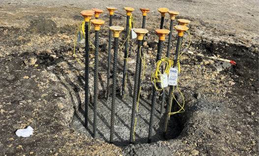
Thermal Integrity Profiling, often called TIP testing, evaluates the heat generated as concrete cures. Cement hydration produces heat, and the temperature pattern within a drilled shaft can provide information about concrete continuity, shaft shape, reinforcing cage position, and potential changes in the concrete section.
Thermal sensors are typically installed along the reinforcing cage before it is lowered into the excavation. The sensors collect temperature data during the curing period, allowing the project team to compare readings at different depths and locations around the cage.
Thermal Integrity Profiling is covered by ASTM D7949, which establishes procedures for integrity testing of concrete deep foundations by thermal methods. The method is used on drilled shafts and other cast-in-place concrete foundation elements where temperature development can be measured during curing.
How TIP Testing Works
TIP testing relies on temperature measurements collected along the shaft length. Thermal wires may be attached to the reinforcing cage in several locations around its perimeter, allowing the test to capture temperature behavior from multiple directions.
Concrete with a relatively uniform geometry and material condition tends to produce a consistent thermal response at a given depth. A lower temperature reading compared with nearby readings at the same elevation can indicate a potential reduction in concrete volume, lower cement content, lower-quality concrete, or another condition that requires review. A higher temperature reading may indicate increased concrete volume or an enlargement in the shaft section.
The results should always be evaluated by qualified personnel. Concrete mix design, shaft diameter, placement temperature, ambient conditions, concrete curing behavior, cage configuration, and sensor locations can all influence the temperature profile.
What TIP Testing Can Show
TIP testing can provide information about potential changes around the reinforcing cage perimeter, rather than only along direct paths between access tubes. This can be valuable when the project team wants information about potential changes in shaft shape or concrete cover around the cage.
Thermal data can also help identify possible cage eccentricity. When the cage is closer to one side of the shaft than another, the concrete cover varies around the cage. Because concrete cover influences the thermal response, this condition may be reflected in the temperature profile.
For projects that need early data review, thermal testing can be particularly useful because data collection begins soon after concrete placement. The temperature profile develops during curing, allowing project teams to begin reviewing results before many other post-placement integrity testing methods are performed.
What is Crosshole Sonic Logging?
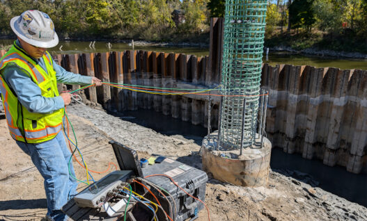
Crosshole Sonic Logging, commonly called CSL, is a non-destructive test method that evaluates ultrasonic wave transmission through concrete between access tubes installed in the drilled shaft. The tubes are generally attached to the reinforcing cage before concrete placement and extend along the shaft length.
After concrete placement, the access tubes are filled with water. During testing, probes are lowered into adjacent tubes. One probe transmits an ultrasonic signal while the other receives it. The test measures the signal travel time and energy between the tubes as the probes move along the shaft depth.
CSL is commonly used on drilled shaft projects, especially where project specifications have established access tube requirements and sonic testing procedures. The method is addressed by ASTM D6760, which covers integrity testing of concrete deep foundations by ultrasonic crosshole testing.
How CSL Testing Works
CSL evaluates the concrete located between access tubes. The quality of the access tube installation is therefore critical to the value of the testing program. Tubes must be securely attached to the reinforcing cage, extend through the intended test length, remain open during construction, and be filled with water before testing.
A signal response that differs from the expected behavior may indicate a potential anomaly between the tested tube pair. Longer travel times, lower signal energy, or signal loss can indicate conditions that require further engineering evaluation.
CSL does not directly identify the exact cause of an indication. The results must be reviewed in relation to construction records, shaft geometry, tube layout, concrete placement procedures, and other project information. When a result raises concern, the engineer may consider additional testing, crosshole tomography, coring, excavation review, or another appropriate evaluation method.
What CSL Testing Can Show
CSL can provide detailed information about concrete quality along the sonic paths formed between access tubes. It is particularly effective when access tube layouts are designed to provide appropriate coverage for the shaft diameter and reinforcement cage geometry.
Because CSL evaluates the concrete between tube pairs, the testing coverage depends on tube number, tube spacing, and tube condition. If a tube is blocked, damaged, or inaccessible, the available testing paths may be reduced. Proper tube installation and protection are therefore essential components of drilled shaft QA/QC.
For many owners and DOT agencies, CSL remains familiar because it has been widely specified for drilled shaft construction for many years. It can fit well into quality programs that already include standardized access tube layouts, testing procedures, reporting formats, and acceptance criteria.
Comparing CSL vs TIP
The main difference in CSL vs TIP is the type of data each method collects. TIP testing measures temperature changes generated during concrete curing. CSL measures ultrasonic signal transmission between access tubes after concrete placement.
TIP can provide information about thermal behavior around the reinforcing cage perimeter and along the shaft length. CSL provides information about concrete quality between access tube pairs. Both methods can identify conditions that need review, but the test coverage and timing are different.
| Comparison Area | Thermal Integrity Profiling | Crosshole Sonic Logging |
|---|---|---|
| Testing Principle | Measures concrete heat generated during curing | Measures ultrasonic signal travel between access tubes |
| Typical Instrumentation | Thermal sensors or thermal wires attached to reinforcement | Water-filled access tubes attached to reinforcement |
| Data Collection Timing | Begins during early concrete curing | Performed after concrete reaches a suitable testing condition |
| Primary Coverage | Around the reinforcing cage and along the shaft length | Between adjacent access tube pairs |
| Potential Information | Shaft shape changes, concrete cover variation, cage eccentricity, potential anomalies | Potential anomalies in concrete between the tested tube paths |
| Key Installation Concern | Correct sensor layout, cable routing, and protection | Correct tube number, tube spacing, continuity, and accessibility |
| Schedule Consideration | Can support early review during curing | Requires post-placement probe access through tubes |
Timing and Schedule Differences
TIP testing begins during the concrete curing period because it depends on heat generated by cement hydration. This can allow early review of shaft information while the project is still progressing through foundation construction.
CSL is generally performed after the concrete has cured sufficiently for ultrasonic testing. This requires the access tubes to remain open and accessible after concrete placement. The testing schedule must account for probe access, water filling, data collection, and engineering review.
For projects with accelerated schedules, the timing difference can be important. An owner or contractor may prefer early thermal data when the goal is to identify potential concerns quickly and reduce delays before proceeding with related construction activities.
Coverage Differences
TIP testing evaluates temperature behavior at sensor locations around the reinforcing cage. This can provide useful information about potential changes in concrete cover, shaft radius, and shaft geometry around the cage perimeter.
CSL evaluates the concrete between access tubes. Its coverage depends on the number and arrangement of the tubes. A well-designed tube layout can provide substantial information about the concrete inside the cage area, but the method is limited to the sonic paths created by the tube arrangement.
The project team should evaluate these coverage differences before selecting a test method. Shaft diameter, reinforcing cage dimensions, expected ground conditions, construction methods, and project risk all affect the appropriate instrumentation layout.
TIP Testing for Early Quality Review
TIP testing can be a strong choice when early information is important to the project. Because data collection begins during curing, the testing team can review temperature development while the shaft is still in its early post-placement period.
This may be beneficial for transmission foundation projects, transportation work, marine construction, and high-production drilled shaft programs where the contractor is installing multiple shafts within a compressed schedule. Earlier review can help the project team communicate quickly about potential concerns before later construction activities become more difficult to adjust.
For projects using connected data systems, a Thermal Integrity Profiler (TIP™) system can support collection and review of thermal measurements from cast-in-place concrete foundations. Cloud-based systems can also help project stakeholders access data remotely when authorized users need to coordinate decisions across multiple locations.
Instrumentation Planning for TIP
The value of TIP testing depends on the sensor layout. Thermal wires must be attached securely to the reinforcement cage and located to represent the areas of interest. Cable routing, splicing, protection, and data collection hardware must also be planned before the cage enters the excavation.
The testing provider, contractor, and engineer should coordinate on the number of thermal wires, their spacing around the cage, the sensor interval, and the anticipated test length. Projects with larger shaft diameters, unusual cage geometry, or higher risk conditions may require more detailed planning.
CSL Testing for Established QA/QC Programs
CSL may be the preferred choice when project specifications already require access tubes and ultrasonic testing. Many DOT agencies, bridge owners, consultants, and contractors have established procedures for CSL installation, testing, reporting, and review.
The method can be particularly practical when the project team has experience with access tube fabrication and understands the testing requirements before cage installation. It may also be a logical choice when the owner’s acceptance process is built around CSL terminology and established evaluation procedures.
For projects requiring experienced field testing and interpretation, Crosshole Sonic Logging (CSL) services can provide testing support for drilled shaft programs that use embedded access tubes and ultrasonic evaluation.
Access Tube Installation Requirements
CSL results depend on successful access tube installation. The tubes should be installed to the required depth, attached securely to the cage, protected during cage placement, and maintained in a condition that allows probe travel.
The tubes must be filled with water for the ultrasonic test. If a tube is blocked, damaged, leaking, or inaccessible, the planned test coverage may be reduced. For this reason, CSL should be coordinated with reinforcing cage fabrication, field handling procedures, concrete placement operations, and post-placement inspection.
Using TIP and CSL Together
TIP and CSL are sometimes used together on projects with high structural importance, difficult ground conditions, large shaft diameters, complex reinforcing cages, or unusually high consequences of failure. The methods are not identical, so using both can provide complementary information.
TIP can offer information about temperature behavior around the cage perimeter and potential changes in shaft geometry. CSL can provide ultrasonic data along direct paths between access tubes. When both methods indicate consistent results, the project team may have greater confidence in the integrity evaluation.
When the methods identify different conditions, the results should not automatically be treated as a conflict. The engineering team should review the test coverage, instrumentation location, construction records, concrete placement conditions, and the specific nature of each indication before determining whether additional investigation is necessary.
Choosing the Right Method for Your Project
The right testing method depends on the project’s risk profile, design requirements, owner specifications, construction schedule, shaft geometry, testing objectives, and available quality documentation. There is no universal answer to whether TIP testing or CSL is always better.
TIP may be the stronger fit when early information, shaft shape assessment, concrete cover variation, and potential conditions around the cage perimeter are important. CSL may be the stronger fit when access tube testing is already required, the owner has established CSL acceptance procedures, or the project needs ultrasonic data between tube pairs.
For critical drilled shafts, the best approach may include both methods as part of a broader drilled shaft QA/QC program. The most reliable integrity evaluation combines testing data with quality construction practices, complete field records, proper instrumentation installation, and qualified engineering interpretation.
Ultimately, the goal of drilled shaft integrity testing is not simply to collect data. The goal is to give project teams the information needed to make defensible, timely decisions about the quality and condition of the completed foundation.