H-Pile Splices
 Traditionally H-pile splices were made by riveting or bolting. They are now routinely made by full penetration butt welding or with patented splicers.
Splicers are generally manufactured as a strong unit prefabricated from carefully formed structural plate and accurately spaced to the thickness of web for each weight of H-pile by a heavily welded spacer. Made as directed, a splice makes a member as strong as an unspliced pile. Ends of the splicer are flared in two directions to a pre-determined shape that guides the end of the H into alignment with the next section.
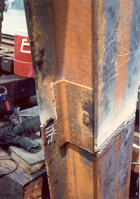
Use of the splicer makes the connection quicker and safer; once the H enters the splicer, it is held against dangerous slippage from movement of the crane or a gust of wind. For moderate additions to vertical piles, in some cases the splicer has been used to hold the added length until the welds could be made at the other edges and across the flanges. This releases the driver, or auxillary-lifting device, at once to continue essential work elsewhere. The close fit holds the pile in alignment. A loose fit would permit wobble and require that the H extensive be held by the crane until it is securely welded. In addition no time is lost welding guides to the H and using wedges for alignment as would be required when splicing an H-Pile without a “factory splice” as the manufactured splice performs this function.
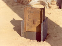 During driving and in service, splices should develop the required strength in compression, bending, tension, shear and torsion at the point of splice. The current AASHTO Bridge Specifications require that a splice must provide the full strength of a pile (for a compression pile full strength in bending is required).
The splicer can be attached in advance to the length of pile to be added. This should be put on the driven length. The attached fabricated splicer will aid in positioning the added length and hold it firmly against dangerous movement. This is especially advantageous when having to drive batter piles or when working off a barge.
For H-Piles a splicer provides for quick extension. The unit is prefabricated with flared ends. A heavy spacer bar is welded to hold the accurately shaped members at about 1/16 in. tolerance over the thickness of any weight of H. This close fit requires that burrs from cutting and other protrusions be removed.
For installation a 7/8 in. x 1-1/8 in. notch is cut in one length only. (Note that the spacer is offset so that only one slot is needed. Be sure that the splicer is turned so it centers on the joint). The notch is cut into the web of the driven section of pile and the splicer is slipped on the pile. Short welds are then made to the flanges near the corners of the splicer. The top section must have flanges chamferred to achieve effective welding. The length of pile to be added is positioned and held while welds across flanges are made. Proprietary H-pile splicers are fabricated from ASTM A 36 steel. This type of splicer has been tested in the laboratory and the results have shown that it provides full strength in bending (as required by the AASHTO Bridge Specifications). The patented splicer allows quick and efficient splicing.
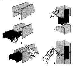 The outside edge of each flange of the H to be added must be beveled to half the thickness of the steel. Irregularities in the contact edge will have a little space for weld metal to penetrate full depth. Make a short fillet weld at each corner of the splicer to the inside of the flange of the H. Weld along the full width of each flange with a minimum 5/16 in. groove weld; 3/8 in. for 1/2 in. or greater metal thickness and 1/2 in. over 7/16 in. steel. Resume driving as soon as the weld cools to “touchable” temperature.
As shown in the sketches, a good weld across each flange and a short weld near each corner of the splicer to the flanges completes the joint. Splices can be placed on the driven length if more convenient for the job. If welds should be inadequate the splicer keeps the two lengths in alignment for continued load carrying ability.
Tack weld each flange of the sleeve to the pile with a 2-1/2 in. long 5/16 in. fillet weld. This can be most effectively placed just below the flare of the splicer. (The closer it is to the end the greater strength it will have for holding an added length of pile while welding is completed. There is no need for welds across the ends of the splicer.) The splice can be placed on either the driven H-pile or the section to be added. If put on the driven length, the four short welds can be made at once. If placed on an H on the ground, the piece must be turned or the welds underneath made after the pile is raised by the crane.
After the next section is set into the splicer and forced to tight contact, a weld is made across the outside of the flanges of the H. Short welds are made near the remaining corners of the splicer. This equals the weld it is not possible to make along the web of the H. Driving can be resumed as soon as the weld cools to the touch.
 NOTE: For any method of splicing, the flanges of the upper section of H must be beveled for welding. Do not bevel ends where driving will be done.
Full penetration butt welds of the H section may be used. Butt welds usually require back-up plates or back gouging. When welding is done in the leads, special precautions must be taken to assure that the upper section does not disengage from the driven length, developing a hazardous condition. Piles usually do not line up at a joint due to tolerances and bends so special wedging devices may be needed for alignment prior to start of welding.
Whenever piles are spliced it is essential that the sections be accurately aligned before welding. The pile sections should be checked for strraightness on each axis by a straight edge before welding.
If there is trouble in getting the splicer on the pile, check for battered ends and for burrs from cutting or burning. Many splices are made to very close clearance, about 1/16 in. This is to assure a full strength splice and to help hold the added section of H pile securely until it can conveniently be welded. Foreign H piles sometimes have more variations than domestic. A “T” made by cutting a short piece of H-pile can be used in driving the splicer on with a sledge.
For all methods of attachment each flange of the upper length of pile should be beveled, leaving 1/8 in. of metal for weld backing. AWS E60 or E70 rod is ordinarily used. Welds on flanges or around plates where used, should be carefully made. Close inspection is essential for plates on webs and especially for all welds across the flanges.
Welding in place without a splice requires exceptional attention, as it is difficult to exactly align and hold the pile sections. There is always a tendency to rush the weld to continue driving or to release a holding crane for other work. The splicer helps to correct for misalignment or flanges out of square and holds the pile so welding time is minimized.
When factory splices are not utilized, splices may be made by full penetration butt welds across both flanges and the web. To attain full penetration welds, plates should be used to back up the weld or the weld should be back gouged to good metal and filled in. For welding, flanges should be accurately aligned with plates and wedges.
Plates may be welded across the joint at the pile ends, either inside or outside the flanges, and on the web. Flange plates should be 1 in. narrower than the flange space available and the web plates the maximum width that can be welded between the flanges. Each plate should be fillet welded along what will be the vertical edge. Ends of the flanges of the upper length of pile must be beveled and a penetration butt weld made across them. Where plates are used they can sometimes be attached in advance to the upper length of a pile in a way to help position and hold it on the driven length.
A bevel is cut to one half the metal thickness on the section to be added (do not bevel where the hammer will strike). A minimum 5/16 in. groove weld is made along the full contact surface. NOTE: For metal thicker than 9/16 the weld should be 3/8 in. and greater for above 3/4 in. steel. Clips should be temporarily welded to one length at the splice for quick positioning of the next length. This will also aid in preventing the pile from moving should a sudden wind gust or lurch of the crane occur. For this direct welding it is desirable to have an additional small crane or cherry picker handling the extension and holding the pile while it is firmly attached. This additional piece of equipment will permit greater efficiency for the pile driver and crew, while maintaining a safe attachment procedure.
-
 SPW911 Sheet Pile Design Software
Rated 5.00 out of 5$150.00 – $599.99Price range: $150.00 through $599.99
 -
 Sheet Pile Design (PDF Download)
Rated 5.00 out of 5$89.00
 -
 Pile Driving (PDF Download)
$89.00
-
 Marine Construction Volumes 1 & 2 (PDF Download)
$157.00
-
 Pile Driving (Book)
$89.00


