


Basic Configuration of Sheet Pile Design Analysis
by Don C. Warrington, PhD, P.E., University of Tennessee at Chattanooga
Introduction
Sheet pile design and analysis is an important part of geotechnical engineering, and is well documented in publications such as Sheet Pile Design by Pile Buck. The advent of software such as SPW 911 has made executing this design a much simpler task than in the past, when charts and graphical methods were employed to accomplish the task.
But someone who is not a regular practitioner may wonder: why is this task so complicated? Why can’t we just use some formulas and be done with it? The purpose of this article is to show why this is so, while at the same time give some idea as to how the charts featured in Sheet Pile Design by Pile Buck came into being and how we can perhaps use these simplified cases to give us some “back of the envelope” understanding of sheet pile design.
Cantilever Sheet Pile Walls
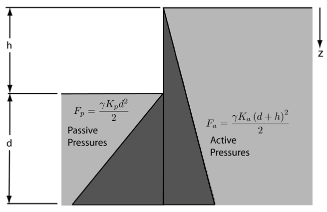
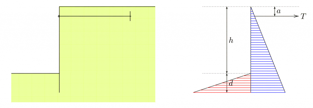
We start with the simplest case: a cantilever sheet pile wall with a uniform stratigraphy and no water to affect the results. This type of system is shown in Figure 1:

In simple terms, sheet piles are supported by the passive pressures below the dredge line offsetting (either in overturning or sliding) the active pressures on the earth side. Since the passive earth pressure coefficient is greater than the active one, the distance d, which is shorter than the active side’s h+d, can accomplish this if d is allowed to a sufficient depth. For this analysis the “simplified method” will be used, which eliminates the reversals of active and passive pressures at the toe of the wall that are analyse in the “conventional method.” This is the same method used by SPW 911.
Let us define some variables, first the earth pressure coefficient ratio:

This is used in the chart solutions featured in Sheet Pile Design by Pile Buck. The next is the dimensionless height below the top of the wall, or

Last we have the ratio of the penetration of the sheeting below the dredge line to the height above, or

The dimensionless moment at any point below the dredge line is

The d’ (and thus d) we are seeking is the point at which is moment is zero, i.e., at the toe of the pile. If we obtain the real root for this equation and then solve for d’, we have
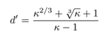
We can see that the depth of penetration below the dredge line depends here on two things only: the height of the sheeting above the dredge line (Equation 3) and the ratio of the passive and active earth pressures (Equation 1.) This underscores our description of the basic principle behind sheet pile walls.
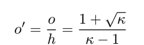
One more important parameter is the maximum moment. If we take the derivative of Equation 4 and set it to zero, we will have the location of the point of zero shear or maximum moment. That location o (and its dimensionless counterpart o’) is given by the equation
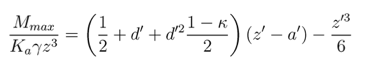
Substituting that result into Equation 4 and dimensionalising it yields the maximum moment,
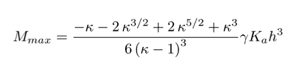
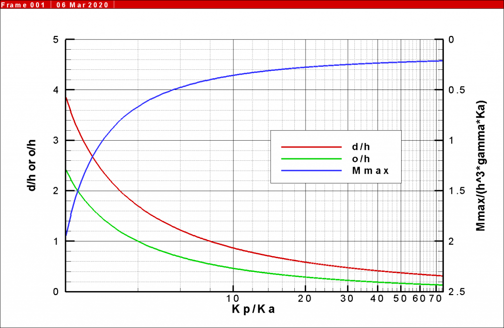
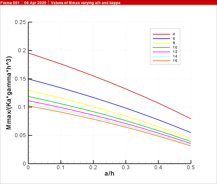
The quantity outside of the fraction is familiar to users of the charts in Sheet Pile Design by Pile Buck. A chart similar to the one shown there is presented in Figure 2.
We can consider an example problem as follows:
- Dry cantilever wall, uniform cohesionless soil , level backfill, Rankine conditions
- φ = 30°, γ = 109.2 pcf
- h = 10’
- Passive reduction for the factor of safety = 1.5. This method of applying the factor of safety is explained in Sheet Pile Design by Pile Buck.
We need to find the penetration below the dredge line d and the maximum moment on the sheeting.
- From Rankine theory, Ka = 1/3 and Kp = 3.
- However, since we should reduce the Kp for the factor of safety, Kp = 3/1.5 = 2. From this κ = 2/(1/3) = 6.
- Substituting this into Equation 5, d’ = 1.22, and thus from Equation 3 d = (1.22)(10’) = 12.2’.
- The simplified method requires that d be increased. Sheet Pile Design by Pile Buck and the online help for SPW 911 explain how that is properly applied. For our purposes we will further simplify the process by increasing the entire penetration below the dredge line by 20%, thus d = 12.2 + (0.2)(12.2) = 14.6’.
- The total length of the sheet pile wall is h + d = 10’ + 14.6’ = 24.6’.
- Substituting the variables into Equation 7 yields a maximum moment of 17,325 ft-lb/ft of wall.
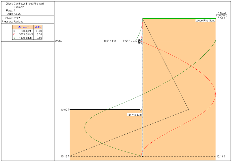
This result can be compared with the output of SPW 911, which yields the result of Figure 3.
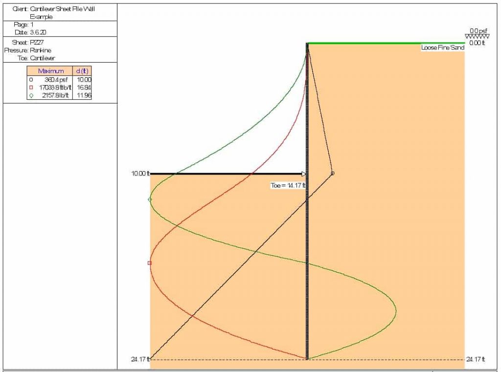
The results of SPW 911 vary little from those of the closed form solution. The greatest variance is in the penetration below the dredge line, which was explained above.
Anchored Sheet Pile Walls
Adding an anchor to the wall complicates the analysis. A schematic of this is shown in Figure 4.
The following likewise appears in Verruijt and van Bars (2007) except some of the nomenclature is different.
In addition to the variables defined earlier, we define

One shortcoming of the anchored wall chart given in Sheet Pile Design by Pile Buck is that it is restricted to walls with a’ = 0.25.
The penetration distance ratio d’ is the solution of the equation

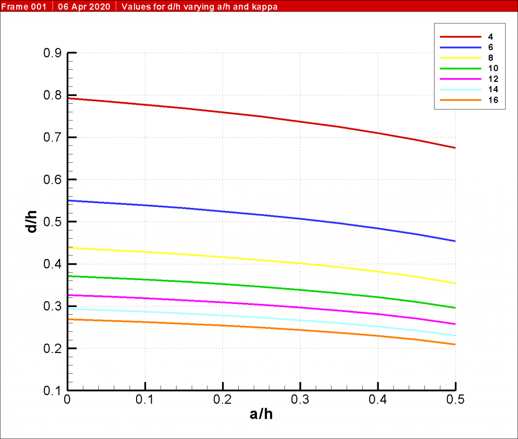
As was the case with Equation 4, this is a cubic equation; however, the solution is considerably more complex in every sense of the word. The simplest way to solve this is numerically. Virtually all spreadsheets, for example, feature Goal Seek, which can be used to solve this equation. Also, a chart showing the relationship of a’ to d’ for various values of κ is shown in Figure 5.
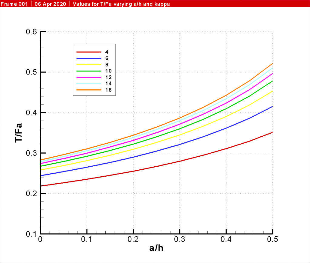
In any case the ratio of the anchor pull T to the total active earth pressure on the sheet pile wall is given by the equation
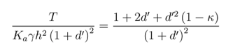
A chart illustrating this relationship (using the same axis scheme as Figure 5) is shown in Figure 6.
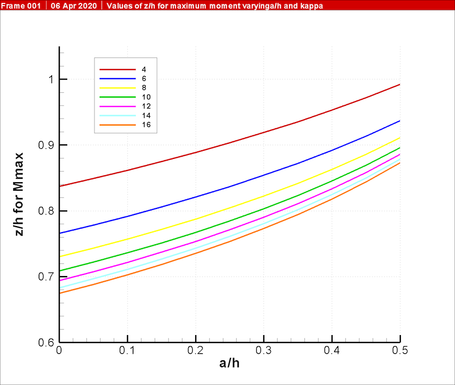
The maximum moment is located (using a similar procedure to that used with cantilever walls) using the equation
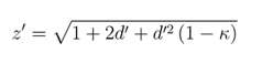
The results of this equation are illustrated in Figure 7.
The dimensionless maximum moment is given by the equation
This is illustrated in Figure 8.
Turning to an example, we will use the same example as with the cantilevered wall except to add an anchor at 2.5’ from the top of the wall. This yields a’ = 0.25. The dimensionless ratios that result from the equations above are as follows:
- d’ = 0.516 (Equation 9)
- Anchor pull ratio = 0.305 (Equation 10)
- z’ for maximum moment = 0.836 (Equation 11)
- Moment ratio = 0.108 (Equation 12)
Substituting, the actual parameters that result are as follows:
- d = 5.16’
- T = 1274.6 lb/ft of wall
- z = 8.37’
- Mmax = 3924.5 ft-lbs/ft
These can be compared with the results of SPW 911, shown in Figure 9. The results are very close.
Discussion
Comparing the cantilever and anchored solutions shows the contrasts between the two. As one would expect, the cantilever wall requires greater penetration below the dredge line than the anchored one. However, the maximum moment in the cantilever wall (and thus the section required to resist it) is much greater than that of the anchored wall. This underscores the inherent advantages of anchored walls, especially for sections (such as vinyl or fibreglass) which have a low section modulus.
There are also some comments specific to anchored walls and the charts shown in Figure 5 through Figure 8.
Although the required penetration can be decreased by lowering the anchor point, the more significant trade-off comes with the maximum moment vs. the anchor pull. The lower the anchor pull, the lower the maximum moment but the higher the anchor pull force. Balancing these two parameters is an important part of anchored sheet wall design. These charts do not include the effect that lowering the anchor point has on the area above the anchor, where cantilever deflections can be significant.
Inspection of Figure 5 also shows that variations in the earth pressure ratio κ have a great deal of influence in the depth of penetration of the sheeting, as was the case with the cantilever walls.
Conclusion
It is worth noting that none of these equations consider the effect of variations in the soil stratigraphy or the presence of water. Absence of either or both is rare in actual sheet piling design. The complexity of the solution rapidly increases with the presence of either, and in current practice the use of software packages such as SPW 911 is necessary. Nevertheless these are useful perhaps as a “back of the envelope” way of estimating parameters of sheet pile design and as a check for the results of software, which is always a good thing in geotechnical design.
References
In addition to the extensive references to Sheet Pile Design by Pile Buck and the online help for SPW 911, the only reference used was Verruit and van Bars (2007), Soil Mechanics. Delft, the Netherlands: VSSD.
Why is sheet pile design considered complicated, and why can't simple formulas be used for analysis?
Sheet pile design involves various factors such as earth pressure coefficients, penetration depths, and moment calculations, making it complex; traditional charts and graphical methods were replaced by software like SPW 911 for more accurate and efficient solutions.
How does adding an anchor affect the analysis of sheet pile walls, and what is the impact on the design?
Adding an anchor complicates the analysis of sheet pile walls, introducing variables like anchor force and a new dimensionless parameter (a'). The design involves solving complex cubic equations, and the relationship between a' and d' is crucial for accurate analysis