Soil Improvement: Methods to Enhance Soft Ground Conditions

View the complete article here.
When designing and constructing a superstructure’s foundation, the enhancement of soft ground conditions can often eliminate the need for a deep foundation. Specialty contractors routinely improve the performance of the ground in situ by compacting, reinforcing, or fixing soil masses and particles.
The following copy details the benefits of these primary soil improvement techniques with a focus on applicable soil types, equipment, procedures, the materials utilized, and quality control.
Note that inherent dangers are associated with these techniques, and thus they should only be implemented by trained and experienced specialty contractors.
Compaction
Dynamic, vibro, grouting, and surcharging represent the primary techniques used to compact or densify soil in situ.
Dynamic (Deep) Compaction
This process involves the repetitive dropping of a heavy weight on the surface of the ground to compact soils
Dynamic compaction is most effective in permeable, granular soils, as cohesive soils can absorb and limit the technique’s effectiveness. The process is primarily used to reduce foundation settlements, seismic subsidence, and liquefaction potential. In organic soils, dynamic compaction has been used to construct sand or stone columns.
Once a three- to four-foot crater is created, the hole is filled with granular material prior to additional drops.
At completion, the soils within three to four feet of the surface will be loose. These surface soils are compacted with a low energy ironing pass. This procedure consists of dropping the weight several times from a height of 10 to 15 feet, this procedure spanning the entire surface area.
Penetration testing is then routinely performed to measure the improvement achieved by the dynamic compaction.
Because the process produces large vibrations, it is important to review adjacent facilities for vibration sensitivity and document their pre-existing conditions prior to the dropping of weight.

Vibro Compaction (Vibroflotation)
This process involves the use of a down-hole vibrator that is lowered into the ground to compact soils at depth. The method is used to increase bearing capacity and reduce foundation settlements, and is most effective in free-draining granular soils below the groundwater table.
The vibroflot consists of a cylindrical steel shell with an interior electric or hydraulic motor that spins an eccentric weight. The vibration is horizontal and the source is located near the bottom of the probe. Common vibration dimensions are 10 feet in length and 1.5 feet in diameter.
Vibrators vary in power from 50 to more than 300HP and are hung from standard cranes. Extension tubes are bolted to the top of a vibrator, allowing it to be lowered to a necessary treatment depth. Electric vibrators have a remote ammeter that displays amperage being drawn by the motor.
Compaction begins at the bottom of a treatment depth, which can extend down to 120 feet. The vibrator is raised at a certain rate or repeatedly raised and lowered as it is extracted. The surrounding granular soils rearrange into a denser configuration of 70 to 85 percent.
Sand is added around the vibrator at the ground surface. This sand falls around the vibrator to its tip in order to compensate for the volume reduction achieved during densification. Coarser backfill can be used instead of sand to improve the effectiveness of the technique, namely in silty soils. Overall, the technique does not densify the sands within two to three feet of the ground surface. This job is typically reserved for steel drum vibratory rollers.
Penetration tests are routinely performed at the midpoint of the probe pattern to determine the degree of improvement achieved, which is itself dependent on the vibrator’s energy, the spacing of vibrator penetrations, the quantity of backfill, and the time spent densifying soil.
Compaction Grouting
This technique densifies soils by injecting them with a low mobility, low slump mortar grout. As additional grout is injected through a drilled or driven pipe, the grout bulb expands, compacting the soils through compression. The soil mass is then reinforced by the resulting grout column, reducing settlement and increasing shear strength.
Grout utilized typically consists of Portland cement, sand, and water. Natural fine-grained soils, fly ash, or bentonite can be added to the mix. Generally, the grout strength is not critical for soil improvement.
Compaction grouting is most effective in free-draining granular soils and low sensitivity soils. The process is known to reduce settlements in collapsible soils, eliminating sinkhole potential. The method can also stabilize existing sinkholes in karst regions.
The process is commonly started at the bottom of a zone to be treated and then proceeds upward. The treatment can be terminated at any depth and is very effective in targeting isolated zones at depth.
Achieving significant improvement within eight feet of the ground surface is difficult unless a contractor utilizes a top-down procedure. In this method, grout is pumped at the top of the treatment zone first. After the grout sets in, a pipe is drilled to the underside of the grout and additional grout is injected. Post-grouting, penetration testing can verify the improvement of granular soil.


Surcharging
This method places soil fill on-site to pre-consolidate existing soil prior to construction. Surcharging improves soils via compression, increasing stiffness and shear strength. Preloading is best suited for soft, fine-grained soils that will experience excessive settlement under a structure’s load.
In partially or fully saturated soils, prefabricated vertical drains are placed prior to surcharge placement, which accelerates drainage and reduces surcharge time. The drains are 4-inch wide strips of corrugated or knobbed plastic wrapped in a woven filter fabric. Typically, 1000-foot-long rolls of drain are fed into a mandrel, which is pushed, vibrated, driven, or jetted vertically into the ground via a mast mounted to a backhoe or crane.
Fill soil utilized for preloading is typically delivered to the area with dump trucks. Dozers are then used to push the soil into a mound. The mound’s height depends on the pressure required to achieve desired improvement. In very soft sites, piezometers and inclinometers may be required to avoid the abrupt placement of fill.
Reinforcement
This method of improvement involves constructing a reinforcing element within the soil mass that does not change the soil properties. Types of reinforcement include stone and vibro concrete columns, along with soil nailing, micropiles, and fracture grouting.
Stone Columns
In this method of reinforcement, columns of compacted, gravel size stone particles are constructed vertically in the ground. The columns improve the performance of soft or loose soils via densification of surrounding granular soil and reinforcement of the soil with a stiffer, higher shear strength column. The stone is commonly compacted with a vibroflot. This method is often used to increase bearing capacity up to 10 ksf and pre-collapse sinkholes prior to construction in karst regions.
Column construction starts at the bottom of the treatment depth, which can extend to depths of 100 feet, and proceeds to the surface.
The vibrator initially penetrates the ground with assistance from its weight, vibration, and the wet jets in its tip. A front-end loader then places stone around the vibroflot at the ground surface. The stone falls to the tip of the vibroflot via the flushing water around the exterior of the vibroflot. The vibrator is then raised several feet and the stone falls around the vibroflot to the tip, filling the cavity that has been formed. The vibroflot is repeatedly raised and lowered in this fashion, compacting and displacing the stone in two- to three-foot lifts. The flushing water is directed to a settlement pond where suspended soil fines settle.
If the dry bottom feed procedure, rather than the wet feed method, is selected, the vibroflot penetrates the ground assisted by its weight and vibrations alone. If difficult penetration is encountered, predrilling through firm soils may be required.
Post-treatment penetration testing and full-scale load tests are often performed post-column installation to measure the improvement achieved in the granular soils.

Vibro Concrete Columns
This method of reinforcement involves constructing concrete columns in situ using a bottom feed vibroflot, which densifies granular soils and transfers area loads through soft cohesive and organic soils. The method reduces foundation settlements and increases bearing capacity, while also serving as an alternative to piling. These columns are typically placed no more than 40 feet below the ground surface.
Installation of vibro concrete columns initially involves lowering or pushing the vibroflot through soft soil until it penetrates the bearing stratum. Concrete is then pumped as the vibroflot is repeatedly raised and lowered by roughly two feet, which creates an expanded base and densifies granular soils. The concrete continues to be pumped as the vibroflot is raised to the surface. Once at the ground surface, the vibroflot is raised and lowered several times to form an expanded top.
During production, it is imperative to monitor the pumping and extraction rates, verifying that the grout pumping rate matches or exceeds the rate at which the void is created as the vibroflot is extracted. These columns can be load tested in accordance with ASTM D 1143.
Soil Nailing
An in situ technique for reinforcing, stabilizing, and retaining excavations and deep cuts, soil nailing introduces small, closely spaced inclusions, typically in the form of reinforcing steel bars, into a soil mass. The face of this mass is then locally stabilized, resulting in a zone of reinforced ground that functions as a soil retention system.
Cohesive soil or weathered rock is best suited for this technique, as the procedure requires the soil to temporarily stand with a near vertical face until a row of nails and facing are installed.
Soil nailing is a top-down method, where a piece of earth-moving equipment first excavates the soil in incremental depths of three to six feet. A drill rig is then used to put the nails in place on three- to six-foot centers. After each row of nails is installed, the excavated face is stabilized by fastening a welded wire mesh to the nails and placing shotcrete.
It’s important to note that soil nail walls are generally not designed to withstand fluid pressures. Therefore, drainage systems are incorporated into the wall. These systems can include geotextile facing, drilled-in-place relief wells, and slotted plastic collection piping. Surface drainage control is also essential.
Extreme care should be exercised when an existing structure is adjacent to the top of a soil nail wall, as movement during soil mass stabilization can cause damage.
Following installation, tension tests can confirm that the intended design bond was achieved.
Micropiles
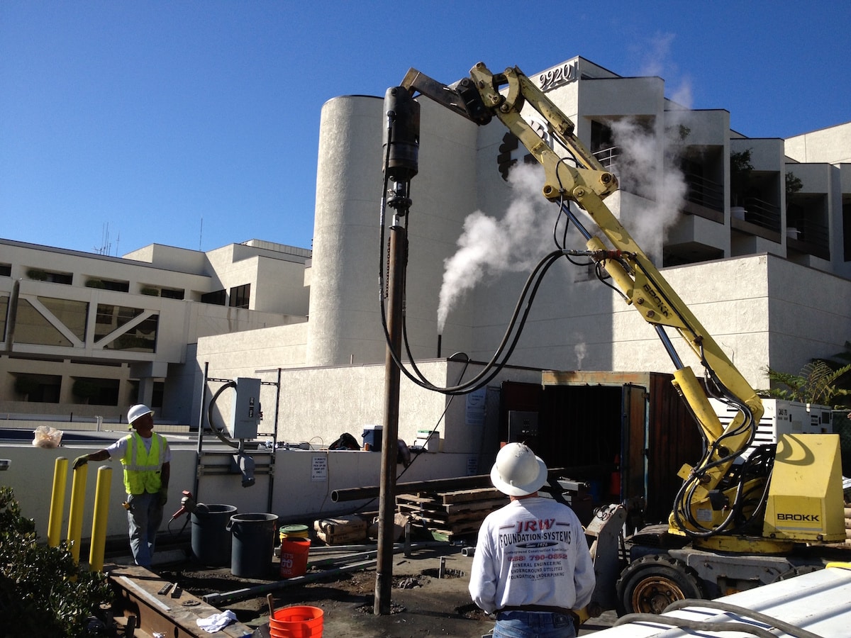
Used in nearly any subsurface soil or rock to transfer a structural load to competent bearing strata, micropiles were originally small diameter, low-capacity piles. Today, advances in drilling equipment have resulted in design load capacities beyond 300 tons and diameters of more than 10 inches.
Micropiles are often installed in restricted access and limited headroom situations. The micropile shaft is commonly driven or drilled into place via a drill rig or small pile driving hammer on a base unit. The micropile consists of a steel rod or pipe. A full-length steel threaded bar is also common, composed of grade 40 to 150 ksi steel.
Prior to construction, a test pile is typically constructed and load tested to 200 percent of the design load in accordance with the standard specification, ASTM D 1143. Throughout installation of the micropile, the drilling penetration rate is monitored as an indication of the stratum being drilled.
Fracture Grouting
Referred to as compensation grouting, this method uses a grout slurry to hydro-fracture and inject the soil between the foundation to be controlled and the cause of the settlement, essentially producing a controlled heave of the foundation.
This technique can be performed in any soil type and is routinely used to reduce previous settlements or prevent the settlement of structures while underlying tunneling is performed.
When performing fracture grouting beneath existing structures, large diameter shafts or pits are constructed adjacent to the exterior of the structure to be controlled. From these shafts, a drill rig horizontally installs the sleeve port pipes beneath the structure. A grout injection tube is then inserted into the sleeve port pipe. Packers on the injection tube are inflated and grout is injected. The packers are then deflated, the injection tube moved to another port, and the process repeated.
It is critical to know where all injection ports are located when installing fracture grouting beneath existing structures. The monitoring of the overlying structure is also critical.
When fracture grouting in expansive soils takes place, multiple injection rods are pushed into the ground via a track-mounted rig—to a treatment depth of 7 to 12 feet. An aqueous solution is then injected as the rods are extracted.
These techniques fix or bind soil particles, increasing the soil’s strength while reducing its compressibility and permeability. Soil fixation is commonly achieved via permeation grouting, jet grouting, or soil mixing.
Permeation Grouting
This process is generally used to create a structural load-carrying mass, a stabilized soil zone for tunneling, and a water cut-off barrier via the injection of grout into highly permeable, granular sands and gravels.
The type of grout used depends on the application and soil grain size. For structural applications in gravel, Portland cement and water can be used. A finely-ground Portland cement is used in course to medium sands. In fine, medium, and coarse sand, chemical grout—most commonly sodium silicate—is utilized.
Grout is typically mixed in batches or stream mixed.
Batch mixing involves integrating a selected volume of grout and injecting it before the next batch is mixed. The amount batched depends on the speed of injection and the amount of time the grout can be held and still remain usable.
Steam mixing involves storing the grout components in several tanks. The grout is then pumped through separate hoses that are combined before the grout reaches the injection pipe.
When conducting permeation grouting for excavation support walls, a rig drills a hole in the soil and fills it with Portland cement grout before insertion of a sleeve port pipe. After the grout has hardened, an injection pipe with two packers is inserted into the sleeve port pipe, which allows the grout to be injected through one port at a time. The injection pipe is then raised or lowered to another port, and the process repeated.
During production, grout volume and pressure should be monitored and documented. The grouted soil can also be cored and tested following operations.
Jet Grouting
This technique serves as an alternative to conventional grouting, chemical grouting, slurry trenching, underpinning, or the use of compressed air or freezing in tunneling. Jet grouting is commonly used to provide excavation support of an existing structure before an adjacent site is excavated to make way for a new, deeper structure.
Jet grouting is effective across a range of soils, and represents a bottom-up process. A drill flushes the monitor to the bottom of the treatment zone. The erosion and grout jets are then initiated as the monitor is rotated and extracted, which forms a soilcrete column. Rotating the monitor through a portion of a circle will create only a portion of a column. Extracting the monitor without rotating will create a panel.
Three traditional jet grout systems exist: single, double, and triple fluid.
The single-fluid system uses only a high-velocity cement slurry grout to erode and mix the soil. This system is most effective in cohesionless soil.
The double-fluid system surrounds the high-velocity cement slurry jet with an air jet and is more effective in cohesive soils than the single-fluid system.
A triple-fluid system uses a high-velocity water jet surrounded by an air jet, which erodes the soil. A lower jet then injects the cement slurry at a reduced pressure. Separating the erosion process from the grouting process equates to higher quality soilcrete. The system is the most effective in cohesive soils.

Soil Mixing
This process is used in a host of general civil works projects to provide excavation, tunneling, and foundation support. The system is most applicable in soft cohesive soils, with the quality achieved being only slightly less than that achieved through jet grouting.
For wet soil mixing, a binder is delivered in a slurry form, with slurry volumes ranging from 20 to 40 percent of the soil volume being mixed. Common binders are Portland cement, fly ash, ground blast furnace slag, and additives. For dry soil mixing, the same materials are dry pumped using compressed air.
In both methods, the binder is injected as a tool and advanced down to assist in penetration. The soil and binder are mixed a second time as the tool is extracted. Single columns or integrated walls are then created as augers are worked in overlapping configurations. Treatment depths down to 100 feet have been achieved via soil mixing.
Foundational Techniques
While most of the compaction, reinforcement, and fixation methods discussed above were developed decades or centuries ago, these methods of improving soft soil masses remain critical to the success of today’s superstructure foundations. Performed by specialty contractors only, these techniques continue to reduce settlement while eliminating the need for deep, costly foundations.
View the complete article here.
What is dynamic compaction?
Dynamic compaction involves the repetitive dropping of a heavy weight on the surface of the ground to compact soils. Dynamic compaction is most effective in permeable, granular soils, as cohesive soils can absorb and limit the technique’s effectiveness. The process is primarily used to reduce foundation settlements, seismic subsidence, and liquefaction potential. In organic soils, dynamic compaction has been used to construct sand or stone columns.
What is Soil Nailing?
An in situ technique for reinforcing, stabilizing, and retaining excavations and deep cuts, soil nailing introduces small, closely spaced inclusions, typically in the form of reinforcing steel bars, into a soil mass. The face of this mass is then locally stabilized, resulting in a zone of reinforced ground that functions as a soil retention system.

