Chapter 12 – Analysis and Design of Anchored Walls and Anchor Systems for Earthquake Loads
- Chapter 1 – Overview of Sheet Piling
- Chapter 2 – Structural Design of Sheet Pile Walls
- Chapter 3 – Overview of Soil Mechanics
- Chapter 6 – Dynamic Earth Pressures
- Chapter 9 – Design of Cantilevered and Anchored Walls Using Classical Methods
- Chapter 12 – Analysis and Design of Anchored Walls and Anchor Systems for Earthquake Loads
- Chapter 13 – Sheet Piling Cofferdams
For a complete version of this document click here.
This section describes the procedures for evaluating the stability and safety of anchored sheet pile walls during earth- quakes. Although these can be evaluated using the classical methods described earlier, the implementation of these has many unique features, and so is treated separately.
12.1. Introduction
For earthquake analysis, the free earth support method is used to determine the required depth of sheet pile penetra- tion below the dredge level and the force the anchor must resist so that excessive sheet pile wall movements do not occur during earthquake shaking. The forces acting on both the sheet pile wall and anchor during the earthquake include the static and dynamic earth pressure forces, the static and hydrodynamic pool water pressure forces and the steady state and residual excess pore water pressure forces within the sub- merged backfill and foundation soils. Because anchored walls are flexible and because it is difficult to prevent some perma- nent displacement during a major seismic event, it is appro- priate to use active and passive earth pressure theories to evaluate dynamic as well as static earth pressures. The Mononobe-Okabe theory is used to evaluate the dynamic earth pressures.
There have been very few documented cases of waterfront anchored walls that have survived earthquakes or of walls that have failed for reasons other than liquefaction.
Hence uncertainty remains concerning the procedures out- lined in this chapter and the difficulty of ensuring adequacy of anchored sheet pile walls during strong earthquake shak- ing (e.g. one rough index is seismic coefficients above 0.2).
One of the few seismic design procedures for anchored sheet pile walls is the Japanese Code. Using the observations regarding the performance of anchored sheet pile walls dur- ing earthquake shaking, the following improvements over past practice are recommended:
(1) Anchors must be placed further away from the wall.
(2) Larger seismic coefficients are required. They are to be assigned with consideration of the seismotectonic structures as well as the characteristics of soil and structural features comprising the wall, the anchorage and its foundation.
(3) There is a limitation upon the build-up of excess pore pressures in backfill.
The procedures outlined in this chapter are to be viewed as interim guidance, an improvement over past practice. An anchored sheet pile wall is a complex structure and its per- formance (e.g. displacements) during earthquake shaking depends upon the interactions between the many compo- nents of the structural system (e.g. sheet pile wall, backfill, soil below dredge level, foundation, and anchorage), which impact overall wall performance. The seismic design of anchored sheet pile walls using the procedures described in this chapter requires considerable judgement during the course of design by an earthquake engineer experienced in the problems associated with the seismic design of anchored sheet pile walls.
As a general design principle, anchored sheet pile walls sited in seismic environments should be founded in dense and dilative cohesionless soils with no silt or clay size parti- cles. The proposed design procedure presumes this to be the case. Strength parameters are to be assigned in accordance with the criteria described earlier.
Additionally, the design procedure is limited to the case where excess pore water pressures are less than 30 percent of the initial vertical effective stress.
12.2. Background
Agbabian Associates117 summarize the performance of anchored sheet pile walls at 26 harbours during earthquakes in Japan, the United States, and South America. Their survey indicates that the catastrophic failures of sheet pile walls are due to the large-scale liquefaction of the backfill and/or the foundation, including the foundation soil located in front of the sheet pile wall and below the dredge level. For those structures that underwent excessive movements but did not suffer a catastrophic failure, there was little or no evidence of damage due to the vibrations of structures themselves. For those walls whose backfill and foundation soils did not lique- fy but did exhibit excessive wall moments during the earth- quake, the survey identified the source of these excessive sheet pile wall movements as:
(1) the soil in front of the sheet pile wall and below the dredge level moved outward (toe failure),
(2) the anchor block moved towards the pool (anchor fail- ure), or
(3) the entire soil mass comprising the sheet pile structure and the anchor block moved as one towards the pool (block movement).
The report identified a number of factors that may contribute to the excessive wall movements, including:
(1) a reduction in soil strength due to the generation of excess pore water pressures within the submerged soils during the earthquake shaking,
(2) the action of the inertial forces due to the acceleration of the soil masses in front and behind the sheet pile wall and the anchor block, and
(3) the hydrodynamic water pressures along the front of the wall during the earthquake.
The Japanese Ports and Harbours commissioned a study by Kitajima and Uwabe118 to summarize the performance of 110 quay walls during various earthquakes that occurred in Japan during the past several decades. This survey included a tally of both damaged and undamaged waterfront structures and the dates on which the earthquakes occurred. Most of these waterfront structures were anchored bulkheads, according to Gazetas, Dakoulas, and Dennehy119. In their survey, Kitajima and Uwabe were able to identify the design procedure that was used for 45 of the bulkheads. This is identified as the Japanese code. Their survey showed that (1) the percentage of damaged bulkheads was greater than 50 percent, including those designed using the Japanese design procedure and (2) the percentage of bulkhead failures did not diminish with time. These two observations indicate that even the more recently enacted Japanese code is not adequate. To under- stand the poor performance of anchored sheet pile walls dur- ing earthquakes, it is useful to review the Japanese code that was used in the design of the most recent sheet pile walls that were included in the Kitajima and Uwabe survey.
12.2.1. Summary of the Japanese Code for Design of Anchored Sheet Pile Walls
Most of the case histories regarding the performance of anchored sheet pile walls during earthquakes that were included in the Agbabian Associates and the Kitajima and Uwabe surveys are for Japanese waterfront structures. To understand the performance of these Japanese waterfront structures, it is useful to review the Japanese design proce- dures that were used for the most recently constructed water- front structures included in the surveys. The Japanese code for the design of anchored sheet pile walls as described by Gazetas, Dakoulas, and Dennehy consists of the following five steps:
(1) Estimate the required sheet pile embedment depth using the free earth support method, with the factor of safety that is applied to the shear strength of the soil reduced from 1.5 for static loadings to 1.2 for dynamic loadings. The effect of the earthquake is incorporated in the analysis through the inertial forces acting on the active and passive soil wedges by using the Mononobe-Okabe method to compute PAE and PPE.
(2) The horizontal seismic coefficient, kh, used in the Mononobe-Okabe relationships for PAE and PPE is a product of three factors: a regional seismicity factor (0.10 ± 0.05), a factor reflecting the subsoil conditions (1 ± 0.2), and a factor reflecting the importance of the structure (1 ± 0.5).
(3) Design the tie rod using a tension force value computed on the assumption that the sheet pile is a simple beam sup- ported at the dredge line and by the tie rod connection. Allowable stress in the tie rod steel is increased from 40 per- cent of the yield stress in a design for static loadings to 60 percent of the yield stress in the design for dynamic loadings.
(4) Design the sheet pile section. Compute the maximum bending moment, referred to as the free earth support moment, in the sheet pile using the simple beam of Step 3. In granular soils Rowe’s procedure is used to account for flexure of the sheet pile below the dredge level. A reduction of 40 to 50 percent in the free earth support moment value is not unusual. Allowable stress in the sheet pile steel is increased from 60 percent of the yield stress in a design for static load- ings to 90 percent of the yield stress in the design for dynam- ic loadings.
(5) Design the anchor using the tie rod force of step 2 increased by a factor equal to 2.5 in the design for both stat- ic and dynamic loadings and assume the slip plane for the active wedge starts at the dredge line.
From the modes of failure observed in the Kitajima and Uwabe study of anchored sheet pile walls that were designed using the Japanese code, Gazetas, Dakoulas and Dennehy identified the following as the primary deficiencies in the Japanese code procedure:
(1) The values for the seismic coefficients, kv and kh, used in the Mononobe-Okabe relationships for PAE and PPE are not determined from a site response analysis but are specified within the Japanese code (kv = 0, and kh is within a narrow range of values for most of the waterfront structures involved in the study).
(2) The resistance provided by the anchor is over estimated because the code allows the anchor to be placed too close to the sheet pile wall such that the passive wedge that develops in front of the anchor interferes with the active wedge devel- oping within the backfill behind the sheet pile wall.
(3) The code does not account for the earthquake induced excess pore water pressures within the submerged soils and the corresponding reduction in the shear strength for the sub- merged soil regions, nor the excess water pressure forces and hydrodynamic forces acting on the sheet pile structure.
Gazetas, Dakoulas, and Dennehy listed only one of the fail- ures of the sheet pile walls designed using the Japanese Code as a general flexural failure. In this case, the structural failure was attributed to corrosion of the steel at the dredge level.
Each of these deficiencies is addressed in the steps used in the design of anchored sheet pile walls using the free earth support method of analysis.
 12.2.2. Displacements of Anchored Sheet Piles during Earthquakes
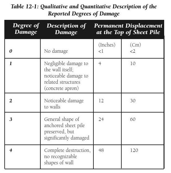
In the Kitajima and Uwabe survey of damage to anchored sheet pile walls during earthquakes, the level of damage to the waterfront structure was shown to be a function of the movement of the top of the sheet pile during the earthquake. The damage can be categorized as one of five levels as given in Table 12-1. Their survey shows that for sheet pile wall dis- placements of 10 cm (4 inches) or less, there was little or no damage to the Japanese waterfront structures as a result of the earthquake shaking. Conversely, the level of damage to the waterfront structure increased in proportion to the magnitude of the displacements above 10 cm (4 inches). Using the infor- mation on the anchored sheet pile walls survey reported in Kitajima and Uwabe and using simplified theories and the free earth support method of analysis, Gazetas, Dakoulas, and Dennehy showed that the post-earthquake displacements at the top of the sheet pile wall correlated to (1) the depth of sheet pile embedment below the dredge level and (2) the dis- tance between the anchor and the sheet pile.
Two anchored bulkheads were in place in the harbour of San Antonio, Chile, during the very large earthquake of 1985. A peak horizontal acceleration of about 0.6g was recorded within 2 km of the site. One experienced a permanent dis- placement of nearly a meter, and use of the quay was severe- ly restricted. There was evidence of liquefaction or at least poor compaction of the backfill, and tie rods may not have been preloaded. The second bulkhead developed a perma- nent displacement of 15 cm, but the quay remained function- al after the earthquake. This bulkhead had been designed using the Japanese procedure with a seismic coefficient of 0.15, but details concerning compaction of the backfill are unknown.
12.3. Design of Anchored Sheet Pile Walls for Earthquake Loadings
12.3.1. Considerations from Static Analysis
In the design of anchored sheet pile walls for static earth pressure and water pressure loads, the free earth support method or any other suitable method may be used to deter- mine the required depth of sheet pile embedment below the dredge level and the magnitude of the design anchor force required to restrict the wall movements to acceptable levels. The interrelationship between the changes in earth pressures, the corresponding changes in the sheet pile displacements, and the changes in the distribution of bending moments along the sheet pile make the free earth support method of analysis an attractive design tool. Rowe’s120 free earth support method of analysis assumes that the sheet pile wall moves away from the backfill and displaces the foundation soils that are below the dredge level and in front of the wall, as shown in Figure 12-1. These assumed displacements are sufficient to fully mobilize the shear resistance within the backfill and foundation, resulting in active earth pressures along the back of the sheet pile wall and passive earth pressures within the foundation in front of the sheet pile wall, as shown in Figure 12-1.
The free earth support method is described in 9.4.2. Rowe’s moment reduction curves can also be used as well.
Various important load and material factors in common practice are as follows: The allowable stress in the sheet pile is usually restricted to between 50 percent and 65 percent of…
-
 SPW911 Sheet Pile Design Software
Rated 5.00 out of 5$150.00 – $599.99Price range: $150.00 through $599.99
 -
 Sheet Pile Design (PDF Download)
Rated 5.00 out of 5$89.00
 -
 Pile Driving (PDF Download)
$89.00
-
 Marine Construction Volumes 1 & 2 (PDF Download)
$157.00
-
 Pile Driving (Book)
$89.00


