Chapter 1 – Overview of Sheet Piling
- Chapter 1 – Overview of Sheet Piling
- Chapter 2 – Structural Design of Sheet Pile Walls
- Chapter 3 – Overview of Soil Mechanics
- Chapter 6 – Dynamic Earth Pressures
- Chapter 9 – Design of Cantilevered and Anchored Walls Using Classical Methods
- Chapter 12 – Analysis and Design of Anchored Walls and Anchor Systems for Earthquake Loads
- Chapter 13 – Sheet Piling Cofferdams
For a complete version of this document click here.
The term sheet piling refers to any retaining wall type that is a) installed into the ground by driving or pushing, rather than pouring or injection, and b) is of relatively thin cross-section and low weight so that the weight of the wall does not assist in the wall’s stability.
The modern sheet piling industry is a little more than 100 years old with perhaps the most important changes in type and selection of products occurring since the early 1970’s.
Sheet piling have been used in a wide variety of applications, especially marine bulkheads and retaining walls where space is limited. In addition to these, a special type of retaining wall is the cellular cofferdam, which are used extensively for both temporary and permanent structures.
1.1. Types of Sheet Piling
Sheet piling are made in a number of materials. The material chosen depends upon a number of factors including both strength and environmental requirements. The designer must consider the possibility of material deterioration and its effect on the structural integrity of the system. Concrete is capable of providing a long service life under normal circumstances but has relatively high initial costs when compared to steel sheet piling. They are more difficult to install than steel piling. Long-term field observations indicate that steel sheet piling provides a long service life when properly designed. Permanent installations should allow for subsequent installation of cathodic protection before excessive corrosion occurs.
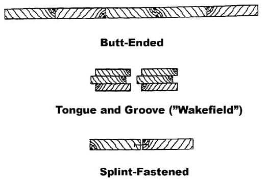
Thousands of years ago, timber logs were placed or pounded into the earth to act as retaining walls or crude dams. Rows of logs were sometimes paralleled and the centre filled with earth to make a stronger wall. Logs were probably lashed together with rope, and a strong back added to combine the logs into a wall. Eventually, it was found that sawn, shaped logs fit together better with less loss of fill through the joints. This lead to the first manufactured sheet pilings having a positive interlocking mechanism between each sheet. Timber sheet piles called “Wakefield” piles were fabricated of three flat wooden pieces. The centre section was offset from the outer sections thus forming a groove and a tongue for joining adjacent piles. A variation of this system was a single timber section in which the groove and tongue were cut to shape. Wakefield type sheet piling is still being used today (see Figure1-1.) Many wood sheet pile walls follow the “Navy Wall” design concept, where loads are transferred to round timber master piles and standard dimensional lumber is used for the sheeting.
The interlocking systems devised for timber or concrete sheet piling have been based on the tongue and groove concept. This method serves to keep the wall aligned while providing a longer path against infiltration with more potential contact points than a simple butt joint. The efficiency of such joints depends on good installation practice but the longterm effectiveness is often in jeopardy due to impact from waves or from settlement. The development of filter cloth membrane material for the lining the backside of these walls has reduced the need for more positive interlocks on walls made of these products. As a consequence, many shallow timber bulkheads are built with regular dimension lumber. Timber sheet piling continues to enjoy an important position, in the industry providing relatively inexpensive bulkheads for homes, commercial property and marinas. Timber sheeting is also used extensively in retainment work for shallow trenches and land cofferdams where water intrusion is not a factor.
1.1.2. Steel Sheet Piling
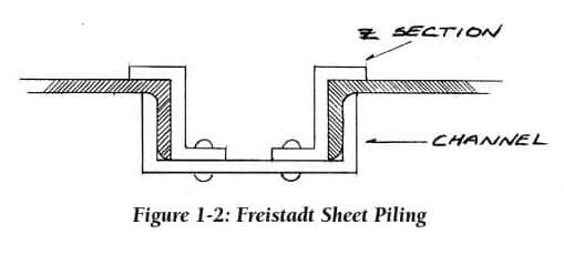
Metal sheet piling was a natural advancement in the evolution of this product as we entered the “Iron Age” in the mid-1800’s. Cast iron was used to make some crude sections, but these were not successful due to lack of ductility. Toward the end of the century, Bessemer steel was developed and mills began hot-rolling I-beams, channels and angles, among other structural shapes. Freistadt-type piling appeared about 1890, fabricated from a rolled channel section as shown in Figure 1-2. Z-bars riveted to the web provided a groove into which the flange of a channel could slide, thus forming a crude but innovative interlock. A “Universal” type sheet piling introduced in Great Britain about 1895 utilized hot-rolled I-beams and special clips to join the flanges of the I-beams together. The efficiency of this wall was low because the I-beams were aligned in the weak structural direction.
1.1.2.1. Larssen Shapes
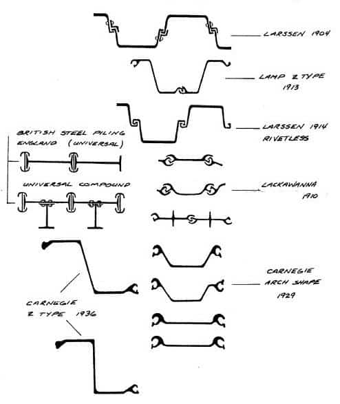
Inventors were striving to develop a sheet piling that would contain interlocks rolled into the beam during the manufacturing process, rather than attached afterwards by riveting. Gregson (USA) patented a bulb and jaw interlock in 1899, however this still resulted in production of a flat section with relatively small section modulus. Trygve Larssen obtained a German patent in 1904 for a deep, hot rolled section that greatly increased the strength and efficiency of steel walls and represented a major advancement. Larssen’s piling wall assumed a “wave shape” when assembled and all subsequent developments for efficient sheet pile walls are based on this concept. Larssen’s section still contained a partially fabricated interlock and it was not until 1914, that a riverless Larssen interlock appeared in Germany.
In the United States, Lackawanna Steel Co. (later acquired by Bethlehem Steel Corp.) was a flat sheet piling shape and several arched types with rolled, integral interlocks as early as 1910. Carnegie Steel Co. (U.S. Steel Corp.) offered three flat sections with rolled-on interlocks and one fabricated section. By 1929, Carnegie’s catalogue illustrated four deep-arch, two shallow-arch and two straight sections. Some of these and other historical sections of sheet piling are shown in Figure 1-3.
1.1.2.2. Z-Type Shapes
Z-shaped piles followed the Larssen concept for a wave shaped profile but with the added advantage that the interlocks are formed on the outer elements of the section. The extra metal is put to best use, since it is well out from the neutral axis of the wall. Larssen interlocks are located on the neutral axis. Surprisingly, Z-shaped piles were produced in Europe as early as 1911. The Ransome profile looked very much like some of today’s lightweight Z-shapes. The deeper Lamp Z-pile introduced about 1913, resembles a modern ball and socket Z-type pile.
In Europe, Z-type shapes fell from favour when the Larssen U-types were developed. Two Z-shapes were introduced in the United States in the 1930’s and became quite popular. PZ-38 and PZ-32 offered wider and deeper sections than any of the arch shaped shapes then available. Z-shaped piles obtained some impetus in the U.S. from the longstanding controversy regarding the actual moment-resisting properties of U and Arch shaped sections.
Z-shaped piles interlock on the wall extremities and provide a solid web connecting the two flanges. When the PZ-27 section was introduced in the 1940’s, its section modulus of 30.2 in3/ft was almost three times that published for the arch section with the identical weight per square foot of wall. This section subsequently became the all-time most popular sheet piling section in history. Z-type shapes are now produced with section modulii ranging from 8.6 to about 85 in3/foot of wall.
The Z-type piling is predominantly used in retaining and floodwall applications where bending strength governs the design and no deflection (swing) between sheets is required.
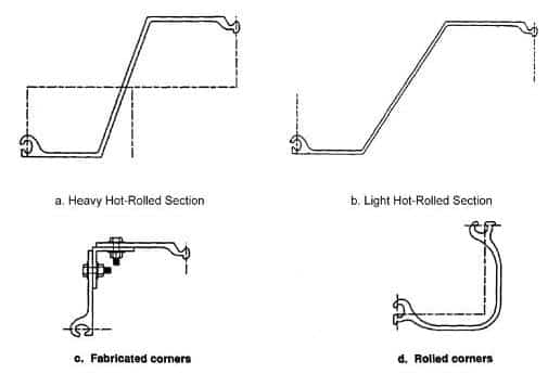
Most producers do not guarantee any swing although some can generally be attained or area can be built by providing some bent pieces in the run. Turns in the wall alignment can be made with standard bent or fabricated corners. Typical configurations are shown in Figure 1-4.
Z-piles are not used in applications when interlock strength is required such as filled cells. These sheets would tend to stretch and flatten in these cases. No minimum interlock strength is offered for this reason. When interlock tension is the primary consideration for design, an arched or straight web piling should be used.
1.1.2.3. Straight Web Sections
Flat profile sections were originally produced only because of mill rolling limitations. Competition and customer demand prompted the expansion into structurally efficient sheet piling. It was discovered that these flat profiles had strength in tension that was advantageous for building circular, filled structures from sheet piling. About 1908 a large cellular cofferdam was built on the Black Rock River in Buffalo N.Y. in order to dewater the site for a new lock. This concept was progressively expanded to include circular and diaphragm-shaped cells for piers and breakwaters that might have formerly been built of timber cribs or masonry.
The use of large diameter, cellular cofferdams was given a special impetus in the 1930’s when the Tennessee Valley Authority204 began a series of hydro dams and navigation locks on that river system in the south-eastern United States. Not only did TVA engineers develop new design methods for designing these large structures, they developed better ways of installing and maintaining them.
Flat sheets have little strength to resist bending, but do have very strong interlocks to resist “hoop” stress. These piles are used almost exclusively for building large, filled cellular structures. Flat sheets must provide some ability to “swing” between sheets so that a circle can be closed. Most manufacturers will guarantee a minimum swing of 8 to 10 degrees between adjacent sheets for standard lengths of piling. For overly long pieces, these warranties must generally be negotiated.
Available interlock strengths must be known in advance in order to design a structure that will be safe against bursting. Most manufacturers will guarantee a “minimum” interlock strength based on tension tests conducted on a number of representative production samples. It has been determined from experience that interlock dimensional tolerances that fall within certain limitations will provide tension values characteristic of the entire production run.2
Flat sheet piling is available only as a hot rolled product, since the cold-finishing process does not provide an interlock with sufficient strength in tension. Interlock strengths have been gradually increased due to the demand to build larger cells for deeper cofferdams.
Most flat sheet piling has been used to construct temporary cellular cofferdams. After the initial use, the sheets are pulled and used in other portions of the project or perhaps sold for another project elsewhere. Other flat sheets are used in permanent structures such as breakwaters, earth containment sites, piers and other applications. Cellular cofferdams are discussed in more detail in 1.2.1.4.
1.1.2.4. Cold Finished Piling
Since the early 1970’s another method of producing steel sheet piling has greatly expanded the availability and the selection of sections. This new method uses hot-rolled sheets in coil form, fed through a series of cold-rolling stands to form “Z” or “arch” shapes complete with a simple, hook-type interlock. This involves a relatively inexpensive capital expenditure compared to the hot-rolled product and has attracted a number of new producers.
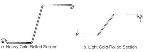
These steel pilings are shallow-depth sections, cold formed to a constant thickness of less than 0.25 inch and manufactured in accordance with ASTM A 857. Yield strength is dependent on the gauge thickness and varies between 25 and 36 kips per square inch (ksi). These sections have low-section moduli and very low moments of inertia in comparison to heavy-gauge Z-sections. Specialized coatings such as hot dip galvanized, zinc plated, and aluminized steel are available for improved corrosion resistance. Light-gauge piling should be considered for temporary or minor structures. Light-gauge piling can be considered for permanent construction when accompanied by a detailed corrosion investigation. Field tests should minimally include pH and resistivity measurements. See Figure 1-5 for typical light-gauge sections.
1.1.2.5. High Modulus Sections
There is a limited but regular demand for sheet piling with strength properties that exceed those available from standard products. These may be required for deep excavations, poor soil conditions, deeper dredge lines and other special conditions. These are discussed in detail in Chapter 14.
1.1.2.6. Interlocks for Steel Piling
There are no established industry standards for interlocks found on steel sheet piling. All manufacturers have the same objectives for the interlocks:
(1) Provide permanent connection of individual sheets in order to form a continuous, relatively water or earth tight wall
(2) Permit reasonably free sliding to grade during installation
(3) Meet the strength requirements for the application.
Various types of interlocks are shown in Figure 1-6.
1.1.2.6.1. History
The original interlocks devised for steel pilings were rather crude, riveted additions to a basic structural shape. When the Larssen U-shaped sheet piling section was introduced in 1903, the interlocks were still attached in this manner. Within a few years however, Larssen shapes with hot-formed, integral interlocks were developed which revolutionized the industry both as to the quality of the product and the cost. The Larssen development was and still is a rather simple shaped “hook” formed on the leading edge of each channel section.
-
 SPW911 Sheet Pile Design Software
Rated 5.00 out of 5$150.00 – $599.99Price range: $150.00 through $599.99
 -
 Sheet Pile Design (PDF Download)
Rated 5.00 out of 5$89.00
 -
 Pile Driving (PDF Download)
$89.00
-
 Marine Construction Volumes 1 & 2 (PDF Download)
$157.00
-
 Pile Driving (Book)
$89.00


