Chapter 4 – Bulkheads
For a complete version of this document click here.
4.1 Types of Construction
General types of construction are shown schematically in Figures 8, 9, and 10. Examples of actual constructions are shown in Figures 11, 12, 13, 14, and 15.
4.2 Selection Factors – Types of Construction
4.2.1 Cantilever Wall. This type of wall tends to creep “out of line” because of variations in soil properties (active pressure and passive resistance). To a degree, this can be compensated for by the use of a heavy cap to stiffen the wall and to increase the radii of curvature of the differential movements which occur. Alternately, consider increasing embedment of the toe in order to reduce total movement, or limit use of a cantilever wall to areas having compact, granular soils. Whatever is done however, a straight line is unlikely to be maintained. Some “sinkage” of the upland should be expected as the ground settles to fill the void resulting from the wall movement.
Increased depth of embedment of the sheet piling is required with accompanying increase in cost and difficulty in driving. As a result, a cantilever wall often is less economical than an anchored wall, particularly if a simple deadman anchorage can be used.
The principal advantage of a cantilever wall often is minimum property encroachment and minimum interference with adjacent constructions.
4.2.2 Anchored Wall With Single Level of Anchorage. This is the usual form of bulkhead (see Figure 16).
4.2.3 Relieving Platform. This type of construction is used to reduce the lateral pressure acting on the sheeting. In essence, the surcharge and a portion of the weight of the fill are carried as vertical load to a deep level where they do not have an influence on the sheeting (see Figure 17).
This allows deeper walls to be built and heavier loads to be supported within the strength limitations of the sections of sheet piling which are commercially available. There is an additional effect of the relieving platform in reducing the lateral pressures acting on the bulkhead wall. This is the screening effect of the piles supporting the platform. For granular soils, tests indicate that where the ratio of pile diameter to pile spacing (ba) is greater than or equal to 0.5, the screening effect is complete and none of the lateral pressure goes to the front wall. For ba = 0 (when no piles are used), full pressure goes to the front wall. For intermediate values of ba, interpolation would be appropriate; however, the bearing piles must be designed to resist the lateral pressures incident to the screening effect. With regard to reduction in pressure on the closure wall due to wall friction (see Figure 18).
4.2.4 Batter Piles in Lieu of Anchor System. (See Figure 9, type D.) Consider batter piles when there is a need to limit property acquisition or where nearby structures would interfere with an anchor system and depth (height of wall) is excessive for use of cantilever wall.
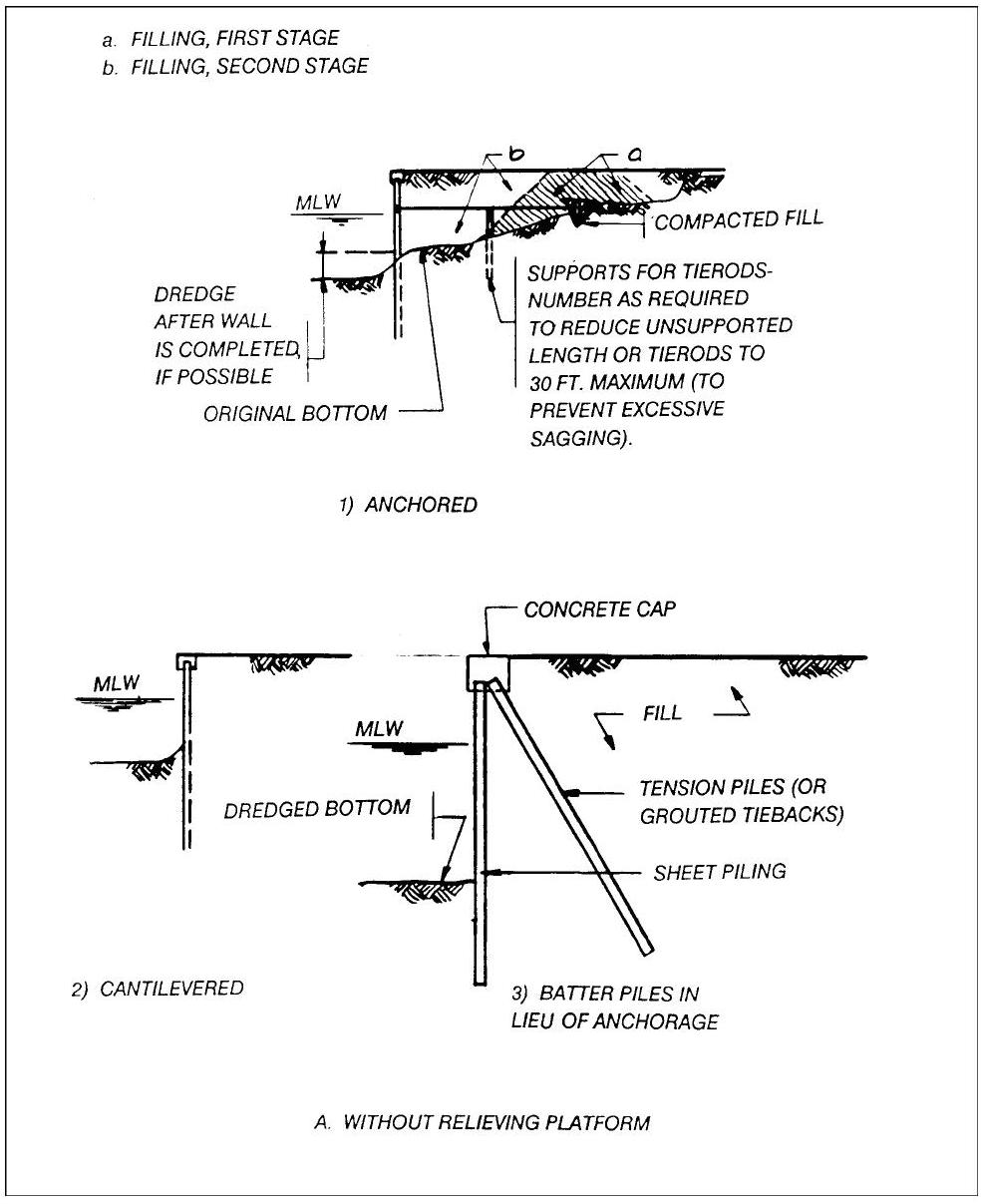
Type of Bulkheads (Example A)
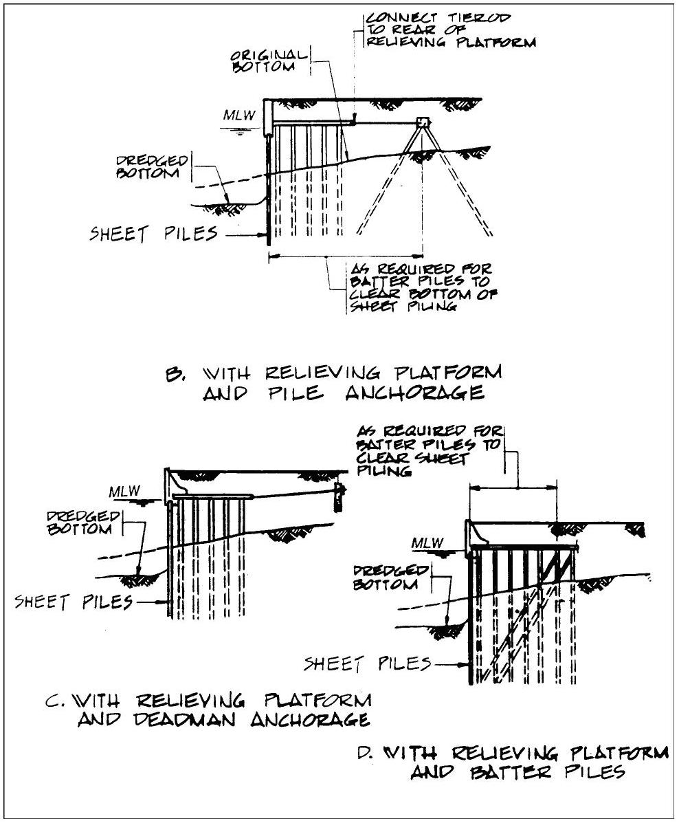
Types of Bulkheads (Examples B thru D)
4.2.5 Hard Bottom. Where impenetrable material exists at shallow depth such that sufficient toe resistance cannot be developed in the overlying soil, consider the use of soldier piles drilled into the hard bottom or set sheeting into a trench, blasted the hard bottom or set sheeting into a trench, blasted out of hard material. For reasons of incompatibility of strains, passive resistance in the hard material normally may not be added to the passive resistance of the looser overlying material. Similarly, the keying effect which can be attained by driving steel piling to refusal into the hard material should not be considered as adding to the passive resistance of the looser overlying material.
4.2.6 Soft Bottom. (See Figure 19.) Where a soft bottom creates problems with developing adequate toe resistance, consider excavating and replacing the soft material or strengthening the material by the use of:
a) sand blanket,
b) sand drains (with surcharge and waiting period),
c) compaction piles, or
d) heavy rock fill which will penetrate the soft material.
4.3 Special Measures. Where a high (deep) wall, heavy surcharge, or poor soil conditions require exceptional bending strength of the front wall, consider the special measures as described in paras. 4.3.1 through 4.3.7.
4.3.1 Use of Lightweight Material. Slag or shell, for example, when used as fill behind the wall, reduces the lateral pressure acting on the wall (see Figures 20 and 21).
4.3.2 Multiple Levels of Anchors. (See Figure 10, Example E.) This requires the use of divers to bolt sheets to lower wales which is facilitated by use of inside wales. The capacity of the sheeting should be estimated by plastic analysis as yield conditions are likely to occur locally in both sheeting and wales. The basic reason is that the sheeting will not be plumb nor will the wales be straight. Excess toe resistance and anchor rod capacity is required to compensate for the uncertainty of the distribution of lateral resistances. Special care is required to equalize the tension in the tie rods.
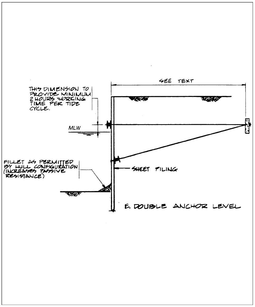
Type of Bulkheads (Example E)
4.3.3 Use of Non-Domestic or Built-up Sections. Figures 22 and 23 illustrate some steel sections which are available from non-domestic sources and some devices for strengthening commercially available domestic materials.
4.3.4 High-Strength Sheet Piling. Steel sheet piling with yield strengths of 50,000 psi (14.66 x 10⁷kg/mm2) or greater, are commercially available.
4.3.5 Modification of Characteristics of Soil Behind Wall. The characteristics of the upland fill may be modified by interposing a dike or blanket of better materials (see Figure 24).
4.3.6 Fixation of Tops of Sheet Piling. (See Figure 25.) This scheme reduces the moment in the sheet piling by fixing the upper end as well as the lower end. In effect it creates a fixed-end beam.
4.3.7 Methods to Reduce Wave Action. (See Figure 26.)
4.4 Types of Front Wall. (See Figure 27.)
4.5 Selection Factors – Types of Front Wall
4.5.1 Sheet Piling. (See Figure 27, Examples A, B, and C.) This type of construction is the usual selection and should be given primary consideration even if the use of cover plates to strengthen available rolled sections is required, the selection of steel, timber, or concrete (for low walls, aluminum, fiberglass, and corrugated asbestos may be considered) is a matter of relative cost. For concrete or timber sheet piling, which displace a large volume of soil during installation, consideration must be given to achieving the required toe penetration without excessive driving and damage to the sheets. Jetting often is required.
4.5.2 Soldier Pile Wall (also called “King” Pile Wall). Where the strength of available sections of sheet piling is insufficient for the proposed height of wall and loading, consider a soldier pile wall (Figure 28, type D). By using heavy soldier beams, large bending capacities can be achieved. The sheeting between the soldier piles is draped to act as a catenary (in tension). In the case of the PZ, PDA, and PMA sections, pure catenary action is not achieved. The fill “arches” between the soldier beams so that the sheeting gets little load. The sheeting is not “designed.” For normal spacing of the soldier piles (about 6 to 12 ft) (1.83 to 3.66 m), and assuming the soil behind the wall does not consist of soft clay or silt, minimum commercial sections of sheet piling are adequate.
4.5.3 Soldier Beams and Lagging. Sometimes a bulkhead can be constructed in the dry. An example is when dredging is to be done after the wall has been completed. In such a case, use of soldier beams and lagging often is a more economical solution than the use of sheet piling. One of the reasons is that the lagging can be virtually any material. Timber, concrete, aluminum, galvanized steel, and corrugated fiberglass have all been used. As with the soldier pile wall, arching between the soldier beams reduces the pressures acting on the lagging so that the lightweight sections can be employed. Theories as to pressure acting on lagging vary from an assumption of full arching wherein pressures may be estimated by considering the soldier beams as a series of silo walls (see Figure 29) to assumptions of partial arching. In its simplest form, partial arching is estimated by applying a reduction factor (often 13 to 12) to the basic trapezoidal pressure diagram. For timber lagging, assuming the use of commercial lumber and not stress graded lumber, the recommendations in Table 1 may be followed.
4.5.4 Close-Pile Wall. (See Figure 27, type C4.) This type of front wall construction once was common and still is economical where logs can be inexpensively obtained. The problem is that the logs (piles) do not fit well together and, despite the best efforts to seal the openings in the wall with various kinds of filters and sheathing, experience demonstrates that loss of backfill is a virtual certainty.
4.5.5 Double Wall. (See Figure 28, type F.) This variation of the soldier pile wall can develop great strength.
4.6 Materials for Front Wall Construction. Use of steel, concrete, and timber is common. General criteria for use in the design and detailing of such construction are presented in para 4.9, and MIL-HDBK-1025/6, General Criteria for Waterfront Construction. Other materials in occasional use include galvanized corrugated sheet metal, corrugated fiberglass, and corrugated aluminum.
4.6.1 Aluminum. Theoretically, aluminum should not be a durable sheeting material. Below the dredge line and on the filled face, the lack of oxygen should inhibit the formation of the usual protective oxide. However, the material reportedly has been used to construct thousands of feet of bulkhead. No special problems have been reported.
4.6.2 General. In general, experience with all of these materials is too limited to define their long-term durability. Under proper conditions, an adequate service life could be realized and their use may be considered. Design should be based on load factors as described in para. 4.9. The limited strength of available sections prevents their use as vertical sheeting in all but low walls. When used as lagging, they find application potential in medium and high walls as well.
4.7 Types of Anchorage. (See Figures 30, 31, and 32.)
4.8 Selection Factors – Type of Anchorage. Use simple concrete wall or sheet pile deadman wherever feasible. A pile supported anchorage, in general, is used only where it is necessary to provide support for the wall before the fill behind the wall can be built up to the anchor level. This occurs when the location is too close to the wall (see Figure 31, Detail No. 4). For usual criteria for locating anchorage, there is ample room to provide for simultaneous development of anchorage resistance with build-up of pressure on the front wall.
4.9 Allowable Stresses
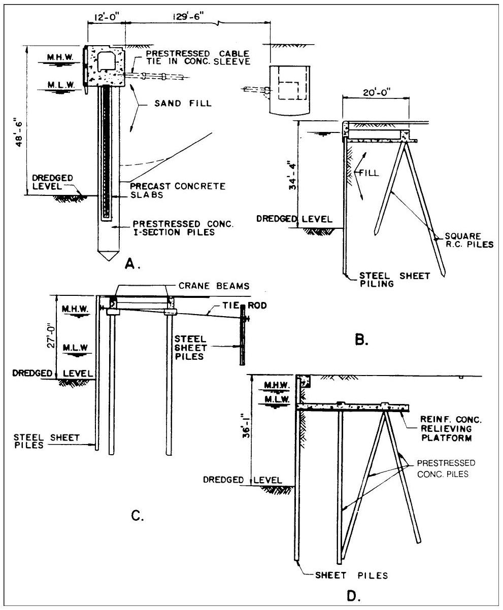
Bulkheads – Actual Construction (Examples A thru D)
4.9.1 Front Wall Materials. For vertical sheeting, use allowable stress = 1.2f, where f is allowable stress given in MIL-HDBK-1002/2 for Service Classification B, or alternatively, reduce overall load factor by 25 percent. Refer to para. 4.5.3. for lagging.
4.9.2 Tie Rods, Fittings, Connections, and Anchor Wall. Use allowable stress = 0.75f, where f is allowable stress given in MIL-HDBK-1002/2 for Service Classification B, or alternatively, increase overall load factor by 33 percent.
Numerous examples of failures of the components of a bulkhead anchor system and of failure due to displacement of the toes of the sheet piles have been reported. No instances of failure due to flexure of the sheeting are known to the authors. In general, it appears that if a bulkhead has ample embedment of the toe and a reserve of strength in the anchorage, it can tolerate substantial deterioration and overstress in the sheeting. Therefore, the toe embedment of the wall and the design of the anchorage should provide a load (safety) factor of 2.0.
4.9.3 Deck Framing. Deck framing, track beams, or other members which function as direct supports for crane, railway, or truck loading shall be designed for Service Classification A. Other elements of support, wherein the impact effect is dissipated into a mass of soil (buried portions of piling, for example), shall be designed for Service Classification B criteria.
4.9.4 Vertical Load on Sheet Piling. (Refer to MIL-HDBK-1025/6.)
4.9.5 Construction Conditions. Allowable stresses under temporary construction loads shall be 20 percent greater than the values indicated above.
4.10 Applicable Method of Design. The various common methods (theories) of the design of bulkheads differ in how they estimate the level of the lower point of inflection in the front wall (see Figure 33). For example, in the free-earth support method no lower point of inflection is assumed. In the fixed-earth support method (and the several empirical variations thereof), a lower point of inflection is assumed to occur at various levels at, and below the level of the mudline in
front of the wall. In a specific case, these different methods can yield vastly different results (see Figure 34). The following text suggests the limits within which each method is applicable, and it is intended to apply where the factor of safety against displacement of the toe of the wall is 2.0. If greater embedment is provided, a lower inflection point may develop even for cases where the freeearth method normally would be applicable. The free-earth support method is the most conservative and may be followed in cases of doubt. For details of these methods, reference is made to DM-7.02 on the design of earth-retaining structures. It is not intended that the discussion of these methods preclude recourse to other design procedures such as Danish Rules where applicable, or to any rational method of design which considers arching and creep effects.
4.10.1 Toe of Wall Embedded in Soft to Medium Fine Grained Soil. Use the free-earth support method.
4.10.2 Toe of Wall Embedded in Loose Sand – Sand Behind Wall. For dredged wall use freeearth support method with moment reduction for flexibility. For backfilled wall, use free-earth support method without moment reductions.
4.10.3 Toe of Wall Embedded in Medium to Compact Coarse Grained Soil. For steel or timber wall, assume hinge at the dredge line. For the case where medium to compact material is overlaid by shallow depth of soft or loose material, assume hinge at top of medium to compact material. For a concrete wall, use the free-earth support method.
-
 SPW911 Sheet Pile Design Software
Rated 5.00 out of 5$150.00 – $599.99Price range: $150.00 through $599.99
 -
 Sheet Pile Design (PDF Download)
Rated 5.00 out of 5$89.00
 -
 Pile Driving (PDF Download)
$89.00
-
 Marine Construction Volumes 1 & 2 (PDF Download)
$157.00
-
 Pile Driving (Book)
$89.00


