Chapter 8 – Slope Stability and Protection
- Pile Buck Guide to Soil Mechanics and Testing
- Chapter 1 – Soil Mechanics Introduction
- Chapter 2 – Identification and Classification of Soil and Rock
- Chapter 2 – Section 1: Soil Formation, Physical Properties, Moisture
- Chapter 2 – Section 2: Soil Surveys, Maps, Investigations, Samples
- Chapter 2 – Section 4: Soil Testing, Equipment
- Chapter 3 – Laboratory Tests and Index Properties of Soils
- Chapter 3 – Section 1: Bituminous Mixtures
- Chapter 4 – Field Exploration, Testing, and Instrumentation
- Chapter 6 – Soil Seepage and Drainage
- Chapter 7 – Analysis of Settlement and Volume Expansion
- Chapter 8 – Slope Stability and Protection
For a complete version of this document click here.
8.1. Introduction
This section presents methods of analyzing stability of natural slopes and safety of embankments. Diagrams are included for stability analysis, and procedures for slope stabilization are discussed.
Overstressing of a slope or reduction in shear strength of the soil may cause rapid or progressive displacements. Thus, embankment stability must be assured prior to consideration of other foundation related items. Embankment foundation problems involve the support of the embankment by natural soil. Problems with embankments and structures occasionally occur which could be prevented by initial recognition of the problem and appropriate design. Stability problems most often occur where the embankment is to be built over soft weak soils such as low strength clays, silts, or peats. Once the soil profile, soil strengths, and depth of water table have been determined by field explorations and field and lab testing, the stability of slopes may be evaluated by comparison of the forces resisting failure with those tending to cause rupture along the assumed slip surface. The ratio of these forces is the factor of safety.
8.2. Types of Failures
8.2.1. Modes of Slope Failure
Principal modes of failure in soil or rock are
- 1) Rotation on a curved slip surface approximated by a circular arc;
- 2) Displacement of a wedge-shaped mass along one or more planes of weakness;
- 3) Lateral squeeze of foundation soil.
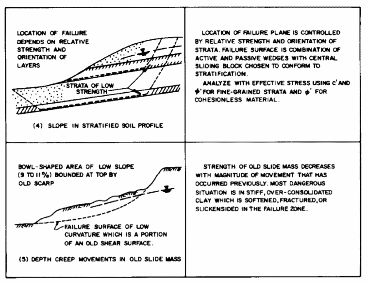
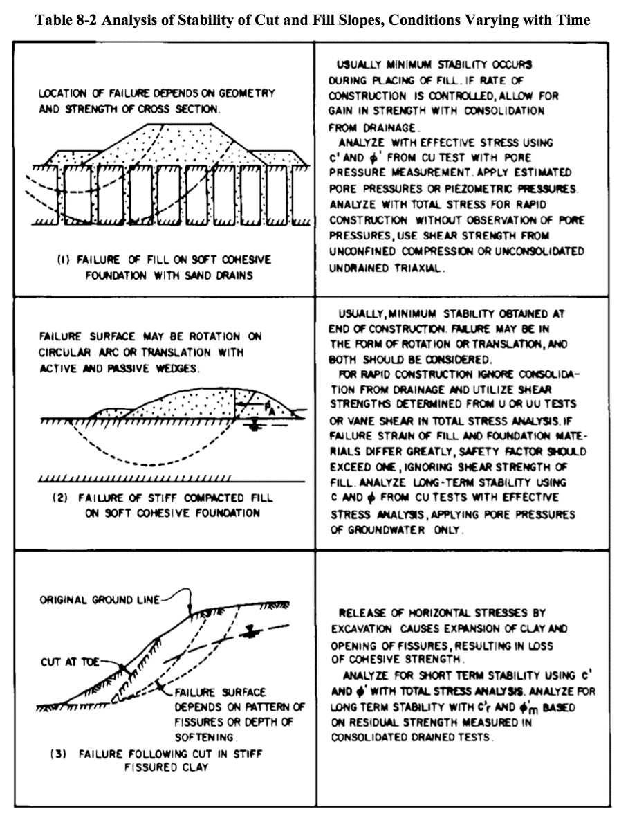
Other modes of failure include toppling of rockslopes, falls, block slides, lateral spreading, earth and mud flow in clayey and silty soils, and debris flows in coarse-grained soils. Table 8-1 and Table 8-2 show more detailed examples of potential slope failure problems in both natural and man-made slopes.
 8.2.2. Causes of Slope Failure
Slope failures occur when the rupturing force exceeds resisting force.
• Natural Slopes. Imbalance of forces may be caused by one or more of the following factors:
o Achangeinslopeprofilethataddsdrivingweightatthetopordecreasesresistingforceatthe base. Examples include steepening of the slope or undercutting of the toe.
o An increase of groundwater pressure, resulting in a decrease of frictional resistance in cohesionless soil or swell in cohesive material. Groundwater pressures may increase through the saturation of a slope from rainfall or snowmelt, seepage from an artificial source, or rise of the water table.
o Progressive decrease in shear strength of the soil or rock mass caused by weatheirng, leaching, mineralogical changes, opening and softening of fissures, or continuing gradual shear strain (creep).
o Vibrations induced by earthquakes, blasting, or pile driving. Induced dynamic forces cause densification of loose sand, silt, or loess below the groundwater table or collapse of sensitive clays, causing increased pore pressures. Cyclic stresses induced by earthquakes may cause liquefaction of loose, uniform, saturated sand layers.
• Embankment (Fill) Slopes. Failure of fill slopes may be caused by one or more of the following factors:
o Overstressingofthefoundationsoil.Thismayoccurincohesivesoils,duringorimmediately after embankment construction. Usually, the short-term stability of embankments on soft cohesive soils is more critical than the long-term stability, because the foundation soil will gain strength as the pore water pressure dissipates. However, it may be necessary to check the stability for a number of pore pressure conditions. Usually, the critical failure surface is tangent to the firm layers below the soft subsoils.
o Drawdown and Piping. In earth dams, rapid drawdown of the reservoir causes increased effective weight of the embankment soil thus reducing stability. Another potential cause of failure in embankment slopes is subsurface erosion or piping.
o Dynamic Forces. Earthquakes, blasting, pile driving, etc., may induce vibrations.
o Fills on Clays. Excess pore pressures are created when fills are placed on clay or silt. As the pore pressure dissipates, consolidation occurs, and the clay or silt strength increases. This is the reason the factor of safety increases with time.
• Excavation (Cut) Slopes. Failure may result from one or more of the factors described above. Additionally, as a cut is made in clay, the effective stress is reduced. This will allow the clay to expand and absorb water, which will lead to a decrease in the clay strength with time. This is the reason the factor of safety of clay cut slope decreases with time. Cut slopes in clay should be designed using effective strength parameters and the effective stress that will exist after the cut is made. An increase in absorbed moisture is a major factor in the decrease in strength of cohesive soils. Water is absorbed by clay minerals and high water contents decrease cohesion of all clayey soils.
o In cohesionless soils, water does not affect the angle of internal friction. The effect of water on cohesionless soils below the water table is to decrease the intergranular (effective) pressure between soil grains (due to buoyancy), and this decreases the frictional shearing resistance.
8.2.3. Effect of Soil or Rock Type
• Failure Surface. In homogeneous cohesive soils, the critical failure surface usually is deep whereas shallow surface sloughing and sliding is more typical in homogeneous cohesionless soils. In nonhomogeneous soil foundations the shape and location of the failure depends on the strength and stratification of the various soil types.
• Rock. Slope failure is common in stratified sedimentary rocks, in weathered shales, and in rocks containing platy minerals such as talc, mica, and the serpentine minerals. Failure planes in rock occur along zones of weakness or discontinuities (fissures, joints, faults) and bedding planes (strata). The orientation and strength of the discontinuities are the most important factors influencing the stability of rock slopes. Discontinuities can develop or strength can change because of the following environmental factors:
o Chemical weathering.
o Freezing and thawing of water/ice in joints. o Tectonic movements.
o Increaseofwaterpressureswithindiscontinuities.Suddenmoistureincreaseinadrysoilcan produce a pore pressure increase in trapped pore air accompanied by local soil expansion and strength decrease. The “slaking” or sudden disintegration of hard shales, claystones, and siltstones result from this mechanism. If placed as rock fill, water percolating through the fill causes these materials to disintegrate to a clay soil, which often leads to settlement and/or shear failure of the fill.
o Alternate wetting and drying (especially expansive shales). o Increase of tensile stresses due to differential erosion.
8.3. Methods of Analysis
Experience and observations of failures of embankments built over relatively deep deposits of soft foundation soils have shown that when failure occurs, the embankment sinks down, the adjacent ground rises and the failure surface follows a circular arc.
- The failure force (driving force) consists of the weight of the embankment. The overturning moment is the product of the weight of the embankment (acting through its centre of gravity) times the lever arm distance to the centre of rotation (Lw).
- The resisting force against movement is the sum at all soil shear strength (friction and cohesion) acting along the failure arc. The resisting moment is the product of the shear strength times the radius of the circle (Ls).The factor of safety against overturning is equal to the ratio of the resisting moment to overturning moment.Equation 8-1: F = Âstotal Ls ÂWLWWhere
- F = factor of safety
- stotal = Total shear strength
- (stotal)(Ls) = Resisting Moment
- W = Weight Force
- (W)(Lw) = Overturning MomentWhen the factor of safety is less than 1, failure will take place.A simple rule of thumb can be used to make a preliminary estimate of the factor of safety against circular arc failure for an embankment built on a clay foundation.
Equation 8-2: Festimate = 6c
g fill H fill
Where
-
- c = cohesion strength of clay
- gfill = Fill Soil Unit Weight
- Hfill = Fill HeightThe factor of safety computed using this rule of thumb should never be used for final design. The simple equation obviously does not take into account such factors as fill strength or fill slope angle and does not identify the location of a critical failure surface. If the factor of safety using the rule of thumb is less than 2.5, a more sophisticated stability analysis is required.However, this rule of thumb can be helpful very early in the design stage to make a quick preliminary check on whether stability may be a problem and if analyses that are more detailed should be conducted. It can also be of use in the field while the boring and sampling is being done. For example, if in situ vane shear tests are being carried out as part of the field investigation, the soils engineer or geologist, can use the vane strength with the rule of thumb equation to estimate the F.S. in the field. This can aid in directing the drilling, sampling, and testing program while the drill crew is at the site and help insure that critical strata are adequately explored and sampled. Finally, the simple rule of thumb factor of safety can be used to check for gross errors in computer output or input.Various techniques of slope stability analysis may be classified into four broad categories that follow.
8.3.1. Limit Equilibrium Methods
Most limit equilibrium methods used in geotechnical practice assume the validity of Coulomb’s failure criterion along an assumed failure surface. A free body of the slope is considered to be acted upon by known or assumed forces. Shear stresses induced on the assumed failure surface by the body and external forces are compared with the available shear strength of the material. This method does not account for the load deformation characteristics of the materials in question. Most of the methods of stability analysis currently in use fall in this category.
The method of slices, which is a rotational failure analysis, is most commonly used in limit equilibrium solutions. The minimum factor of safety is computed by trying several circles. The difference between various approaches stems from (a) the assumptions that make the problem determinate, and (b) the equilibrium conditions that are satisfied. The soil mass within the assumed slip surface is divided into several slices, and the forces acting on each slice are considered. The effect of an earthquake may be considered by applying appropriate horizontal force on the slices.
8.3.1.1. Fellenius Method
8.3.1.1.1. Overview
The simplest and most basic limit equilibrium method is known as the Fellenius Method of Slices.The Fellenius Method assumes that the moment arm is the same for both the driving and resisting forces, i.e, that these forces are collinear.
This method was developed by the Swedish geotechnical pioneer Wolmar Fellenius (1876-1957). His grandson Bengt is in his own right eminent in pile dynamics and deep foundations. The Fellenius Method as shown here is enhanced by details from Coduto, D.P., Geotechnical engineering: Principles and Practices. Upper Saddle River, NJ: Prentice-Hall, 1999.
Equation 8-3: F = Âstotal ÂW
The free body diagram shows the failure surface is divided into slices and the following basic assumptions are made:
- The available shear strength of the soil can be adequately described by the Mohr-Coulomb model, Equation 5-10.
- The factor of safety is the same for all slices
- The factors of safety with respect to cohesion (c) and friction (tan f ) are equal.
- All forces (shear and normal) on the sides of each slide are ignored.
- The pore water pressure is taken into account by reducing the total weight of the slice by the water uplift force acting against the slice baseTo compute the factor of safety for an approach embankment using the Fellenius method, the step-by-step computational procedure is as follows:
- Draw cross-section of embankment and foundation soil profile using either 1″ = 10 feet or 1″ = 20 feet scale both horizontal and vertical.
- Select a circular failure surface.
- Divide the circular mass above the failure surface into 10-15 vertical slices.238
- Compute The Total Weight Wt Of Each Slice. The weight of each slice is the product of the cross- sectional area of the slice and the unit weight of the soil (assuming a unit weight of embankment thickness is assumed for computational purposes.) If groundwater is present the buoyant effect of the water must be taken into account, as will be shown in the examples below.
- Compute sv tanf (frictional resisting force) for each slice. Note that the effect of water is to reduce the normal force against the slice base and thus reduce the frictional resisting force (sv tanf ).
- Compute CL (resisting force due to cohesion for each slice.)
- Compute tangential driving forces.
- Sum resisting forces and driving forces for all slices and compute factor of safety. The computations for the last four steps should be entered systematically in a form. Obviously, such a computation is ideal for a spreadsheet program.
The Fellenius method is generally conservative but does not taken into consideration the friction between the slices, which compromises its accuracy.
8.3.1.2. Other Methods of Slices
There are many other stability analysis methods available besides the Fellenius Method, such as Bishop’s Method, Janbu’s Method, etc. These methods are primarily variations and refinements of the basic method of slices. The differences in the more refined methods lie in the assumption made regarding the shear and normal forces made on the sides of slices. The method of analysis that should be used to determine a factor of safety depends on the soil type, the source of and confidence in the soil strength parameters, and the type of slope that is being designed. Only qualified experienced geotechnical personnel should perform soil design analyses.
8.3.6. Required Safety Factors
The following values should be provided for reasonable assurance of stability:
- Safety factor no less than 1.5 for permanent or sustained loading conditions.
- For foundations of structures, a safety factor no less than 2.0 is desirable to limit critical movements at foundation edge.
- For temporary loading conditions or where stability reaches a minimum during construction, safety factors may be reduced to 1.3 or 1.25 if controls are maintained on load application.
- For transient loads, such as earthquake, safety factors as low as 1.2 or 1.15 may be tolerated.
8.4. Effects of Soil Parameters and Groundwater on Stability
The choice of soil parameters and the methods of analyses are dictated by the types of materials encountered, the anticipated groundwater conditions, the time frame of construction, and climatic conditions. Soil strength parameters are selected either on the basis of total stress, ignoring the effect of the pore water pressure, or on the basis of effective stress where the analysis of the slope requires that the pore water pressures be treated separately.
8.4.1. Total vs. Effective Stress Analysis
The choice between total stress and effective stress parameters is governed by the drainage conditions that occur within the sliding mass and along its boundaries. Drainage is dependent upon soil permeability, boundary conditions, and time.
• Total Stress Analysis. Where effective drainage cannot occur during shear, use the undrained shear strength parameters such as vane shear, unconfined compression, and unconsolidated undrained (UU or Q) triaxial compression tests. Field vane shear and cone penetration tests may be used. Assume f = 0. Examples where a total stress analysis are applicable include:
o Analysisofcutslopesofnormallyconsolidatedorslightlypreconsolidatedclays.Inthiscase little dissipation of pore water pressure occurs prior to critical stability conditions.
o Analysis of embankments on a soft clay stratum. This is a special case as differences in the stress-strain characteristics of the embankment and the foundation may lead to progressive failure. The undrained strength of both the foundation soil and the embankment soil should be reduced in accordance with the strength reduction factors RE and RF in Figure 8-11.
o Rapid drawdown of water level providing insufficient time for drainage. Use the undrained strength corresponding to the overburden condition within the structure prior to drawdown.
o End-of-construction condition for fills built of cohesive soils. Use the undrained strength of samples compacted to field density and at water content representative of the embankment.
8.4.3. Stability Problems in Special Materials
• Overconsolidated, Fissured Clays and Clay Shales. See Table 8-2. Cuts in these materials cause opening of fissures and fractures with consequent softening and strength loss.
o AnalysisofCutSlopes.Forlong-termstabilityofcutslopesuseresidualstrengthparameters c’r and f’r from drained tests. The most reliable strength information for fissured clays is frequently obtained by back figuring the strength from local failures.
o Old Slide Masses. Movements in old slide masses frequently occur on relatively flat slopes because of gradual creep at depth. Exploration may show the failure mass to be stiff or hard; but a narrow failure plane of low strength with slickensides or fractures may be undetected. In such locations, avoid construction which involves regrading or groundwater rise that may upset a delicate equilibrium.
- Saturated Granular Soils in Seismic Areas. Ground shaking may result in liquefaction and strength reduction of certain saturated granular soils. Empirical methods are available for estimating the liquefaction potential.
- Loess and Other Collapsible soils. Collapse of the structure of these soils can cause a reduction of cohesion and a rise in pore pressure.o Evaluate the saturation effects with unconsolidated undrained tests, saturating samples under low chamber pressure prior to shear. See above for evaluating collapse potential.
- Talus. For talus slopes composed of friable material, f may range from 20o to 25o. If consisting of debris derived from slate or shale, f may range from 20o to 29o, limestone about 32o, gneiss 34o, granite 35o to 40o. These are crude estimates of friction angles and should be supplemented by analysis of existing talus slopes in the area.
8.5. Lateral Squeeze of Foundation Soil
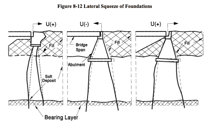
Field observations and measurements have shown that some bridge abutments supported on piling driven through thick deposits of soft compressible soils have tilted toward the backfill. Many of the structures have experienced large horizontal movements resulting in damage to the structure. The cause of this problem is the unbalanced fill load, which “squeezes” (consolidates) the soil laterally. This “lateral squeeze” of the soft foundation soil can transmit excessive lateral thrust which may bend or push the piles out, causing the abutment to rotate back toward the fill, as illustrated in Figure 8-12.
Two questions that need to be considered in design are:
- Can tilting occur?
- If so, how can the amount of horizontal movement be estimated?8.5.1. Tilting
Experience has shown that if the applied surface load imposed by the fill weight exceeds 3 times the cohesive shear strength of the soft soil, i.e.,
Equation 8-7: c < g fill H fill 3
Then this lateral squeeze of the foundation soil and abutment tilting can occur.
Therefore, using the above relationship, the possibility of abutment tilting can be evaluated in design. For all practical purposes, the fill unit weight can be assumed at 125 pcf. The cohesive strength c of the soft soil must be determined either from in situ field vane shear tests, triaxial tests on high quality undisturbed Shelby tube samples.
8.5.2. Estimation of Amount of Horizontal Abutment Movement
The amount of horizontal movement the abutment may undergo toward the fill can also be estimated in design. This data provides a basis for estimating horizontal abutment movement for similar problems, providing a reasonable estimate of the post-construction fill settlement is made, using data from consolidation tests on high quality undisturbed Shelby tube samples. Note that the data for the structures listed in the previous summary showed horizontal abutment movement to range from 6 to 33% of the vertical fill settlement, with the average being 21%.
Therefore, if the fill load exceeds the 3c limit, then the horizontal abutment movement that may occur can reasonably be estimated as 25% of the vertical fill settlement, i.e.,
Equation 8-8: Horizontal Abutment Movement = Fill Settlement 4
8.5.3. Design Solutions to Prevent Abutment Tilting
The best way to handle the abutment tilting problem is to prevent it by getting the fill settlement out before the abutment piling are driven.
If the construction time schedule or other factors do not permit the settlement to be removed before the piling can be driven, then the problems resulting from abutment tilting can be provided for by the following design provisions:
- Use sliding plate expansion shoes large enough to accommodate the anticipated horizontal movement.
- Make provisions to fill in the bridge deck expansion joint over the abutment by inserting either metalplate fillers or larger neoprene joint fillers.
- Design piles for downdrag forces due to settlement.
- Use steel H-piles for the abutment piling since steel H-piles are capable of taking large tensile stresses without failing.
- Use backward battered piles at the abutment and particularly the wingwalls.
Movements should also be monitored so that predicted movement can be compared to actual.
-
 SPW911 Sheet Pile Design Software
Rated 5.00 out of 5$150.00 – $599.99Price range: $150.00 through $599.99
 -
 Sheet Pile Design (PDF Download)
Rated 5.00 out of 5$89.00
 -
 Pile Driving (PDF Download)
$89.00
-
 Marine Construction Volumes 1 & 2 (PDF Download)
$157.00
-
 Pile Driving (Book)
$89.00


