Pier & Wharf Construction Part III: Load Requirements

View the complete article here.
When constructing a pier and wharf, one of the most important considerations is the weight that the structure must be able to bear. The load requirements of a given facility must be carefully analyzed prior to construction to ensure that it can safely handled the expected traffic.
Dead Loads
The first consideration for a pier and wharf facility load requirement should be its dead load. A dead load is the weight of the structure as a whole, which includes all permanent attachments (such as light poles, utility booms, mooring hardware, service utility lines, vaults, sheds and platforms). To best plan for the life of the facility, an analysis of both present and future attachments should be made. When making these assessments, the actual and available construction material weights should be used.
The design of fixed piers and wharves are typically controlled by the load requirements for live and lateral loads. For this reason, overestimating the dead load will not usually negatively impact the overall cost of the facility. For tension or uplift controlled design, overestimating dead loads can be problematic. Similarly, overestimating dead loads for floating piers and wharves can lead to significant cost increases.
Vertical Live Loads
A vertical live (or moving/movable) load is a critical factor to analyze in the construction of a pier and wharf facility. The specific type of loading that will take place at the structure will play an important part in design considerations.
For trucks, loadings should be performed in accordance with American Association of Statate Highway and Transportation Officials Standard Specifications for Highway Bridges. An impact factor of 15% should be applied for the design of slabs, beams and pile caps; the structural elements below pile caps do not need to be designed for impact.
Rail-mounted crane loading is common on many pier and wharf facilities. For many cranes, such as container cranes, there are various capacities, configurations and gages available. For this reason, the final design should not be made without more specific information from crane manufacturers. An increased gage and reach will result in a higher dead weight of the crane, and a higher wheel load. An impact factor of 20% should be added to the maximum listed wheel loads for deck slabs, crane girders and pile caps.
On open and floating piers and wharves, truck cranes are typically used. These vehicles have significant operational restraints. For this reason, realistic loading should be specified for truck cranes.
For loading on railroad tracks, a live load of 8,000 pounds per feet of track should be used. Slabs, girders and pile caps should be designed with an impact factor or 20%.
Generally, piers and wharves are not low enough in the water to be subject to buoyant forces. However, some portions of the structure, including vaults and utilidors, may be subject to these forces due to their position in the water. These are uplift forces, applied at the rate of 64 pounds per square foot for every foot of submergence below water level.
Loading can be applied in a number of ways. For concentrated loads, such as wheel loads and outrigger float loads from pneumatic-tired equipment (trucks, truck cranes, forklifts, etc), the loads should be applied at any point on the structure. The equipment can be placed in any direction on the facility, with the orientation causing the maximum force considered for design purposes.
As a general rule, both uniform and concentrated live loads should be applied in a logical manner, avoiding simultaneous live loading from pneumatic-tired equipment in the same area. However, uniform live loads should be assumed for crane tracks. If railroad tracks are located between crane tracks, then contractors should take into account track loads for both trains and cranes — but maximum loads for each track do not need to be assumed.
When designing short span elements such as deck slabs and trench covers, it is important to take concentrated loads into consideration. This includes the loads from trucks, forklifts, mobile cranes and straddle carriers. For the design of beams, pile caps and supporting piles, uniform loading is the more important consideration (such as in mobile crane float loading, rail-mounted crane loading and railroad loading).
Horizontal Loads
Just as critical as vertical loads, horizontal loads on piers and wharves must be taken into account by contractors prior to the construction of a facility. These factors play an important role in determining the type of elements used to disperse the forces that may act upon a structure and protect it from damage over time.
For piers and wharves, a primary function is the berthing and mooring of ships. A berthing load can be substantial, particularly when a ship is brought in with the help of two or more tugboats. A ship may impact the pier or wharf during berthing, particularly if acted on by wind, current, waves, or tidal forces. A fender system between the ship and facility can help to reduce the berthing energy and force transmitted to the structure. The amount and location of the force transmitted will depend on a number of factors, including the type of structure, the type of ship, approach velocity and angle, and the fender system used.
Once a ship is moored at a facility, forces may act on it to impact a pier and wharf facility. These forces may include winds, currents and waves. Determining mooring loads involves examining factors such as the direction and magnitude of winds, currents and waves, the number and spacing of mooring points, the exposure of the berth and orientation of the vessel, the layout of the mooring lines, the elasticity of mooring lines, and the load conditions of the vessel. If the facility is in sheltered waters, wave forces are not generally a consideration. However, for all moored ships, current and wind will act upon it, creating a force. Computer simulation programs are often useful to simulate potential mooring loads.
When analyzing mooring loads, one of the key elements is how the ships are moored to piers and wharves. A ship is moored by securing its mooring lines to fittings on the deck of the facility, which transmits mooring forces to the pier and wharf through tension in the lines or when the ship bears on the structure. The design and spacing of deck fittings should be planned carefully to control mooring loads when possible. However, the ships using the facility may still use a different arrangement of mooring lines and separators, so a pattern of mooring that is least favorable to the structure should be assumed when determining mooring loads.
Once a ship has been moored, winds, currents, and waves will act upon it, resulting in movement of the ship. A pier and wharf facility should be designed with a fender system, mooring arrangement and mooring lines that will minimize the impact of these ship motions and the forces transferred to the structure.
In some situations, it is not practical or economical to situate a pier and wharf facility for the maximum winds, currents and waves at a given site. In these situations, it is expected that a ship will either take on ballast or go to sea to reduce the effect of these forces acting on the vessel. However, there may be cases where a ship cannot readily leave berth. Contractors should consider allowing space for high-capacity storm bollards along the centerline of a pier or inboard edge of a wharf to allow a ship to be tied up at a more favorable line angle.
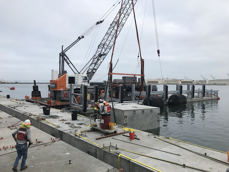
When designing a pier and wharf structure, mooring forces should be factored into the construction process. The structure itself should be able to hold a ship at berth for the maximum wind velocity in a multiple berth pier.
If the pier and wharf facility is located in a seismically active area, it must be able to resist earthquake forces. This can be achieved in accordance with specified state and local standards, or through dynamic analysis of the structure. Floating structures are not usually directly affected by seismic events, but may be subject to waves created by earthquakes, such as a tsunami. Any mooring systems that are used should be carefully analyzed if it is subject to ground motions.
Pressure from the earth and water may also impact a pier and wharf facility. This may occur with or without the presence of an earthquake or other weather events. Earth pressures may act on retaining structures, causing lateral movements of the structure. Generally, wharf retaining structures that are conservatively designed for static loading conditions may be better able to withstand this type of force than those designed more economically. Water level differentials may also cause pressure on facility elements, due to tidal fluctuations and/or groundwater accumulations. The design of sheet pile bulkheads, cells and curtain walls, as well as the stability of embankments and fills, should be carefully considered, particularly in seismic areas.
Thermal loads are another important aspect to be analyzed, as pier and wharf structures may expand or contract due to temperature differentials. Fluctuations in temperature can cause a build up in thermal forces. However, piers and wharves constructed along waterfronts will generally have less of a temperature swing, given the moderating impact of the water. Unballasted decks may see a large difference in temperature through the depth, particularly when compared to ballasted decks, solid-type piers and wharves and floating structures.
Other weather elements may come into play with a pier and wharf structures, such as the action of floating ice on a facility. Generally, freshwater ice will cause less pressure than seawater ice of the same size and thickness, and broken floes will cause less pressure than solid ice sheets.
Load Combinations
After each factor is considered individually, the combination of various load types should be analyzed to construct a pier and wharf facility that is able to withstand both the traffic on the deck, the action of the boats moored there, and the natural forces acting upon it. This requires a consideration of the load combinations that may act upon each component of the structure and the foundation.
Determining load requirements for a pier and wharf facility can be a complicated process, requiring the use of computer models and predictions about the anticipated use of the facility. By using best estimates, and planning for the maximum possible load, a contractor can ensure the long life of a pier and wharf structure.
View the complete article here.
What are dead loads in the context of pier and wharf construction, and why are they important?
Dead loads refer to the weight of the entire structure and permanent attachments; they are crucial as they impact the overall design and must be carefully estimated for construction planning.
How should contractors account for mooring forces in the design of a pier and wharf structure?
Mooring forces should be factored into the construction process by planning for maximum wind velocities, considering the ship's mooring arrangement, and implementing a fender system to minimize the impact of ship motions on the structure.

