Pier & Wharf Construction Part IV: Fender Systems

View the complete article here.
When constructing a pier and wharf facility, one of the critical factors that must be taken into consideration is the fender system. This is the interface between the ship and shore facility that acts as a buffer during the berthing of a ship. The fender system absorbs or dissipates the impact energy of the ship, ideally without causing permanent damage to either the vessel or the facility. For this reason, a well-designed fender system is crucial to the overall function of a pier and wharf project.
This article explores the various aspects of fender systems as it relates to constructing pier and wharf facilities, from understanding berthing practicing to selecting and designing fender systems. If you are tasked with the construction of a pier and wharf facility, read on to learn more about this essential component.
General Considerations
The first step in the process of designing a fender system is analyzing the greater concern: protection of the structure or of the vessel. For solid piers and wharves, which are relatively inflexible, protection of the ship is more important. With comparatively flexible pile-supported piers, wharves and dolphins, protection of the structure is the greater concern.After the ship has been berthed and is moored to the facility, the fender system will continue to transmit environmental loads, such as wind, waves and current, on the ship to the structure. For low-profile ship berthing, the fender system will also provide a physical barrier to prevent the vessel from going under the pier.
As a functional matter, fender systems should be designed to absorbed the ship’s berthing energy in any structural type of pier or wharf, within the working stress or acceptable deformation range as defined by the contract. Note that fender systems are comparatively less expensive than either the ships that will berth against it or the facility itself. As such, some damage to this system is both permissible and acceptable. If there is a berthing accident, the fender should be sacrificed rather than the berth, any part of the structure, or the ship. Similarly, because it is more expensive to repair a ship’s hull than a damaged fender system, all fender systems should be able to prevent deforming ships’ hulls.
Berthing Energy Determination
Berthing energy is a key factor that determines the type of fender system that should be utilized in a pier and wharf construction project. There are a number of methods that can be used to determine berthing energy: kinetic, statistical, and scale.
The kinetic model is the most-commonly used method, and is also the oldest. It is used when the displacement tonnage of the ship is known. The statistical model is dependent on fender layout as well as construction of the site, including the distance between piles. It is based on actual measurements of the energy of the impact at existing berths. The scale model utilizes a small scale model to test the berth in a hydraulic laboratory. This type of test requires experienced interpretation, and may suffer from scale and viscosity effects.
Types of Fender Systems
Fender systems work by either absorbing or dissipating the energy of the berthing ships, converting it from kinetic energy into potential energy. This may happen in a number of ways, from deflection of a fender pile, compression of a column of rubber, deformation of a foam-filled cylinder, pressuring of a pneumatic fender or torsion of a steel shaft. Some fender systems — namely, hydraulic fenders — also absorb energy in the form of heat. Most systems that can be practically applied use potential energy conversion.
There are seven potential components in a fender system. First, fender piles, which may be made of timber, steel, or prestressed concrete. These piles may be connected to a chock and waler system at the deck level, then supported by rubber fender units at the bullrail.
Second, end-loaded rubber fenders work through the elastic compression of hollow rubber cylinder elements that have small length-to-diameter ratios. To minimize wear, steel fender panels with special rubbing material facing is generally used. These components are usually attached directly to the structure as a cell fender.
Third, side-loaded rubber fenders are hollow rubber units that will deform by attempting to flatten when loaded at their side. These fenders are available in four shapes: trapezoidal, square, circular, or D-shapes. The potential energy of side-loaded rubber fenders is stored by both compression and bending the rubber elements. These fenders do not absorb large amounts of energy, and as a result, are typically used in combination with other components. They are generally installed at the top of fender piles in noncontinuous pieces.
Fourth, rubber shear fenders store potential energy as elastic shear deformation of the rubber. Rubber shear fenders are generally manufactured as a solid block of rubber vulcanized between two metal plates. This type of fender is sensitive to proper manufacturing, as it depends on the bond between steel plates and rubber.
Fifth, buckling fenders will accept an axial load until it buckles laterally. Buckling fenders are used with an abrasion or protector panel, as they are not designed for direct contact with a moving ship. Because they can absorb high energy with a constant reaction force, buckling fenders are popular for berthing large ships.
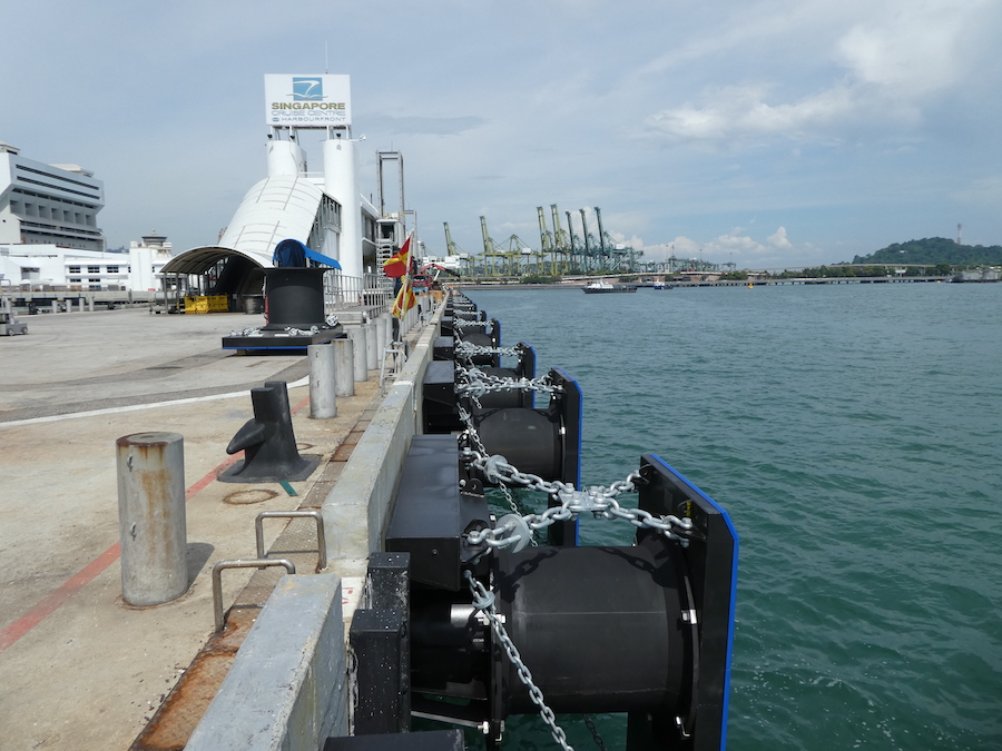
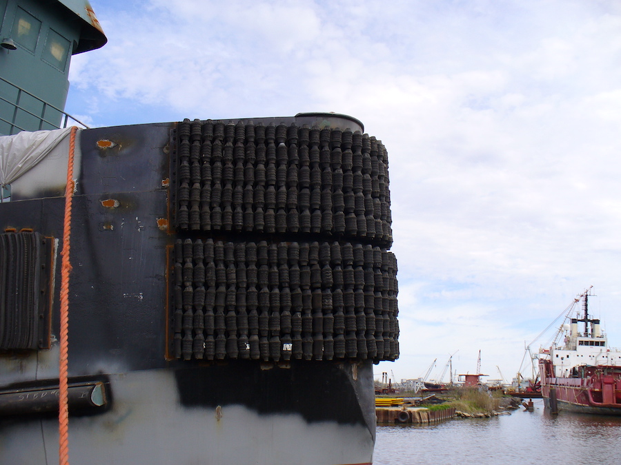
Sixth, pneumatic fenders store potential energy through the elastic compression of a confined volume of air. The energy absorption characteristics can then be changed by varying the internal pressure of the air, with a relief vale or deflection limiter to prevent a blowout. These fenders provide a uniform hull pressure, as they have a uniform surface pressure. There are three primary types of pneumatic fenders that may be used in pier and wharf construction. Air block and air cushion fenders have shells that are chemical bonded and mechanically coupled to a mounting plate that can be attached to the berthing structure. A floating pneumatic fender is usually cylindrical with hemispherical ends. It is then attached to the facility with chains, floating on the water. A tire pneumatic fender involves a large-diameter tire that is mounted on a roller-backed axle. This type of fender is well-suited for corners of a structure where an approach may be difficult.
These components may be used separately or in combination to form a fender system, along with the structure itself. With a proper fender system in place, ship deformation should be rare. There are a number of systems that can be used to prevent damage to both vessels and the pier and wharf facility. The five most common are discussed in detail below.
A combination of fender piles with side-loaded rubber units is frequently used in commercial and naval facilities. It involves a series of fender piles that are closely spaced, connected by chocks and walers, with rubber fender units mounted between the waler and facility. Diagonal chains from the structure to the waler finishes the fender system. The joints between the chocks, walers and pile heads should be tight. The ships can either be berthed directly or through a log camel in this system. This type of system offers flexibility in berthing, as ships of different sizes and types can be accommodated. However, this fender system is not recommended for solid and other types of piers and wharves where full deflection of the piles will be prevented. In addition, the use of floating camels may result in concentrating the energy on just one or two piles. For this reason, the rubber fender units should be sized so that the ships can be directly berthed without camels.
For direct berthing of surface ships, directly mounted fender units may be a good choice. Here, individual fender units are attached to the pier or wharf face. This is a cost-effective choice for solid piers and wharves with narrow tidal ranges and narrow vessel size ranges.
Floating fender units are a better option when surface ships of many sizes must be berthed. This fender system involves foam-filled or pneumatic fender units along with a backing system. These units can be positioned to float with the tide, and designed so that they can be moved as berthing plans change.
A combination system may be made of any of the above systems to make up for what another system lacks. For example, a berth may have floating fender units, directly mounted fenders at specific points, and then a pile-rubber system in-between. Working closely with engineers can allow you to choose a fender system that best meets the needs of the pier and wharf facility.
Finally, a monopile system involves the use of a floating ring-shaped fender unit that rides up and down on a large steel pile that has been driven to the seabed. Low friction bearing pads are installed on the inner surface of the hull, which allows the fender unit to rotate and slide on the pile. A monopile fender system is best used for corner protection, as well as for entrances to narrow slips.
Selection and Design of Fender Systems
When selecting and designing a fender system, a contractor must taken a number of factors into consideration. Beyond cost, these issues go into the suitability of the system for the facility itself — and whether the fender system will be able to perform as desired over time.
As an initial matter, the system must be able to absorb the kinetic energy of the berthing vessel. It also must have a minimal reaction force, which is the force that is exerted on the ship’s hull and the structure doing impact. Hull pressure must also be limited so as to avoid causing permanent damage to the berthing ship.
Contractors must consider the amount of deflection (the distance that the face of the fender system moves when absorbing the ship’s energy) when selecting and designing a fender system. The relationship between reaction and deflection will determine the stiffness of the fender system chosen.
The system must be able to withstand long-term contact without degrading over time. This includes contact involving wind, current, waves and tides during loading and unloading. Friction between the face of the fender system and the ship’s hull is also a factor to be analyzed, as it may have an impact on the performance of the fender system.
The degree of the berth’s exposure to severe environmental conditions may govern the design’s mooring conditions. In addition, the ability of the crew to appropriately berth the ship will impact the fender’s energy absorption ability, and should be analyzed.
Both the initial cost of the fender system should be considered, as well as its operation, maintenance, and repair. If maintenance is to be frequent or expensive, a simpler system may be preferred. If there are a great number of berthings expected, a higher expenditure for the system may be justified.
If a particular type of fender is more frequently used in a given location, it may be considered, as its performance in similar conditions can be evaluated.
Finally, the type, size and shape of ships that are anticipated to use the facility should also be determined. The fender system should be able to accommodate the full range of ships that are expected to use the facility. If ships with unusual hulls may berth at the structure, special attention should be paid to the fender system. Similarly, the fender system must be useable during all water levels.
Keep in mind that in most cases, a ship will only make contact with a small length of a fender system at a time while berthing. For this reason, a discrete fender component should be designed to be able to provide the full energy, with two components installed per berth.
Fender piles, backing members and other non-rubber components are not affected by temperature fluctuations, and should perform normally. However, rubber fender units will become stiff in colder temperatures, and their performance may be significantly impacted. The ability of rubber units to absorb energy should be evaluated based on the lowest expected temperature.
Fender systems place a crucial role in pier and wharf structures. By absorbing and dissipating the energy of berthing ships, these systems protect both the facility and the vessels. As a result, properly selecting and designing fender systems is an important part to the overall function of a pier and wharf facility.
View the complete article here.
What factors should be considered when selecting a fender system for pier and wharf construction?
Considerations include the ability to absorb kinetic energy, minimal reaction force, limited hull pressure, deflection, long-term durability, exposure to environmental conditions, maintenance costs, and accommodation of various ship sizes.
How does the berthing practice of a ship impact the design of a fender system?
The berthing practice influences fender system selection; for instance, large ships assisted by tugs will approach parallel to the berth, while unassisted ships may arrive at a slight angle, affecting initial contact with the fender system.

