INTERVIEW: Pile Dynamics, Inc.
Pile Buck’s interview with Pile Dynamics, Inc. (PDI), the largest manufacturer of industry-standard, high quality deep foundation testing solutions, worldwide. Established in 1972, PDI continues to innovate, develop, manufacture and supply state-of-the-art QA/QC testing and monitoring products and software for the deep foundations industry.
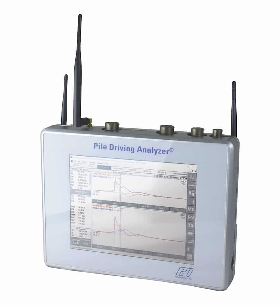
PB: I understand that PDI offers a range of products for driven piles, drilled shafts & bored piles, and ACIP/CFA & DD Piles. Over the years, we’ve heard quite a bit about the Pile Driving Analyzer® (PDA) System so I’m assuming this is your most popular product? What can you tell us about the PDA?
PDI: The Pile Driving Analyzer® (PDA) is the benchmark in foundation construction for quality assurance testing devices. In the mid-1960’s one of PDI’s Founders, Professor G. Goble was the principal investigator in a research project to develop new technologies for pile testing, which was funded by the Ohio Department of Transportation. This research led to the development of the Case Method and CAPWAP® analysis, which led to the creation of the electronic device now known as the PDA.
Initially, the PDA was used on driven piles. With modifications and development, the PDA now can be used on driven piles, drilled shafts, ACIP piles, micro piles, and helical piles, and most types of deep foundations. It is the most widely utilized device in the deep foundation industry and is employed worldwide.
PB: On a quick side note, how often do PDA sensors need to be recalibrated?
PDI: Pile Dynamics, Inc. (PDI) and the American Society for Testing and Materials (ASTM) D4945 recommend that sensors be recalibrated every two years despite how often they are used. Additionally, PDI suggests recalibrating sensors if they exhibit questionable data before two years. PDI’s policy is to recalibrate any sensor returned to its Maintenance Department for checkup or repair.
PB: Would you like to add anything regarding the software that accompanies the PDA? Where can someone learn to use this software?
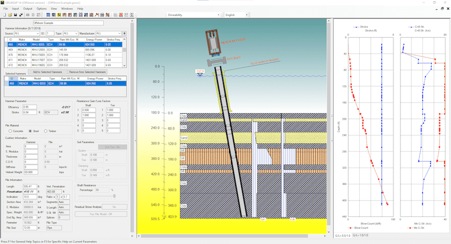
PDI: Because the PDA can be used on a variety of pile types, several software programs are available to fit every testing need. In fact, we just released the newest version of our wave equation analysis program, GRLWEAP14, which simulates motions and forces in a foundation pile when driven by either a vibratory or impact hammer. There are several updates and enhancements in this release. A full list can be found on our website. In addition, the commonly used software, CAPWAP® (Case Pile Wave Analysis Program) is a program that estimates total bearing capacity of a pile or shaft, as well as resistance distribution along the shaft and at the toe. The program inputs the force and velocity data obtained with a PDA to perform a soil resistance test. Also included in a PDA system are PDA-S with iCAP® to calculate capacity at the time of testing; PDIPLOT2l and PDI-Curves.
The PDA also offers add on software, such as PDA-DLT Software which allows multiple configurations of force measurement for drilled shafts. PDA SPT Analyzer Software allowing energy transferred to an SPT rod measurement. And, SiteLink® Technology for remote testing capabilities when the engineer is away from the job site.
The training on the use of the software varies depending upon the complexity of the particular software. For certain software products, the training can be done online either live or via pre-recorded trainings, allowing maximum flexibility for the user. For other software, the training is done live either in person or virtual.
PB: How is the pile weight accounted for in dynamic testing?
PDI: Dynamic tests and static load tests can both determine the additional load that can be placed on the pile top. There is a slight distinction, however, in that dynamic testing ignores the pile weight. An exception arises when testing a long pile. The load test is made on the pile’s top. Following, a section of the pile load is removed. An engineer can add the discarded pile weight to the test load. This is different from a static soil analysis. During a static soil analysis, engineers calculate the supported loads and the pile weight together.
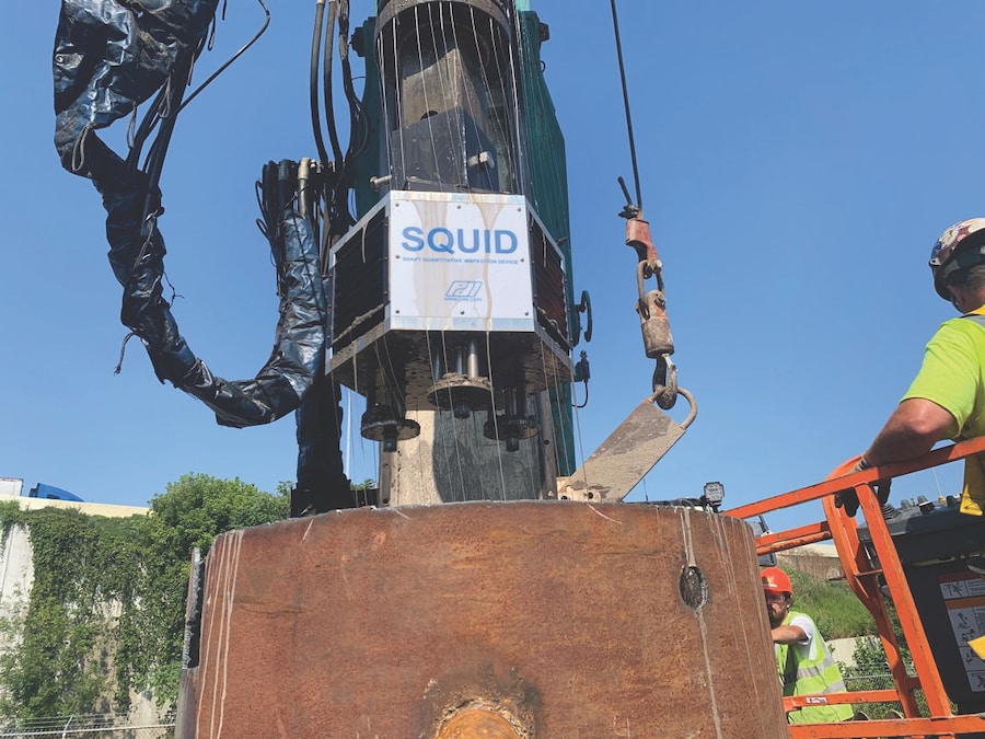
PB: I’ve been told that your Shaft Quantitative Inspection Device (SQUID), one of your newer products, is considered by many to be an essential tool for bored pile and drilled shaft foundations. What can you tell us about the SQUID?
PDI: The SQUID system is unique in that it can offer a data-driven assessment of a drilled shaft’s base. Other products utilize cameras, which are helpful for visualizing cleanliness, but are subjective, sometimes hard to see images through the cloudy slurry, and do not offer the same accuracy as the SQUID. The device has three penetrometers that are displaced at the bottom of the shaft. The SQUID provides a real quantifiable assessment of the shaft bottom so the engineers and owners can make accurately evaluate the shaft bottom. The displacement and force measurements are presented both graphically and in tabular form for assessment by the appropriate engineer. The engineer can be onsite or remotely at any location where there is internet available to receive data and approval of the base cleanliness can be done in minutes. Testing is simple and quick.
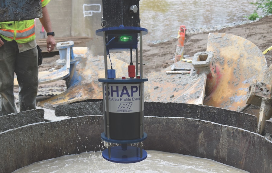
PB: And how about your Shaft Area Profile Evaluator (SHAPE®)—another crucial device for drilled shafts, I’ve been told—I understand that it can provide a visual representation of foundation excavation before concrete is poured?
PDI: That is correct, SHAPE can quickly be lowered into a drilled shaft via Kelly bar or winch deployment system before concrete is poured. The SHAPE is lowered into the slurry-filled shaft, and takes 360-degree scans at a rate of one scan per second. With a scan rate of 1 scan per second, the SHAPE can be lowered at a very rapid rate (typically 1 foot per second) minimizing the time to casting the concrete into the shaft. The sensors collect and send the data back to the engineer, who can then assess the shaft’s shape, verticality, and profile. SHAPE’s software creates a 3D visualization of the shaft at the jobsite for real-time assessment. allowing the engineer to confirm if the shaft meets the design specifications. As with the SQUID, SHAPE analysis can be done remotely in real time, saving time and money for the project.
PB: I’m just curious—How far can the SHAPE® descend into a drilled excavation?
PDI: Because we specialize in deep foundations, we have designed the SHAPE to be able to collect data in excavations as deep as 200 meters (656 ft).
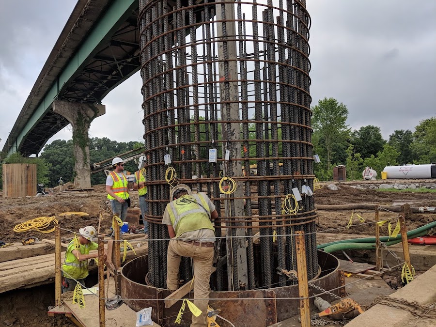
PB: Would you like to mention any other products?
PDI: Like the SHAPE and SQUID devices, our Thermal Integrity Profiler (TIP) is a relatively new technology that evaluates shaft integrity. TIP uses the heat generated by curing cement to assess the quality of drilled shafts/bored piles, augered cast in place/continuous flight auger and drilled displacement piles. It is also be used for quality control and shape evaluation of jet grouted columns, slurry walls, and diaphragm walls. TIP evaluates the entire cross-section over the entire length of the foundation element. Results are available shortly after shaft installation is concluded: TIP reveals necks or inclusions, bulges, variations in concrete cover, and the shape of the shaft and cage alignment. The TIP System includes TAG and TAP-Edge units providing Cloud-enabled capabilities such as real-time data collection, allowing an engineer, designer and contractor to evaluate data from any location, often saving time and money with early shaft evaluation.
Of course, PDI offers a variety of educational resources for those who use our products. We offer webinars and in-person seminars, along with individual product training for engineers and technicians.
PB: Ending on an educational note, is there a common mistake (or obstacle faced) that you’ve witnessed engineers make during testing and application over the years? Do you have any final tips or suggestions?
PDI: A common obstacle a project can face, is believing that testing increases overall project costs. However, many case studies have proven that using the PDA saves project costs by reducing the number of piles needed or reducing the pile lengths for the project while still meeting the design intent. There are cost savings that can be found in almost all testing methods. For additional information, our library of research papers can be found on pile.com which highlight these cost savings.

