


INTERVIEW: GRL Engineers
Pile Buck’s interview with GRL Engineers, Inc, a professional engineering firm established to provide specialized testing, analysis, and consulting services to the deep foundation industry.
PB: Tell us about GRL Engineers.
GRL: In 1964, researchers at Case Institute of Technology in Cleveland, Ohio, embarked on the project that pioneered dynamic pile testing by the Case Method. In 1976, the founders, including Dr. George Goble, Dr. Frank Rausche, and Mr. Garland Likins, incorporated GRL to provide consulting services utilizing the Pile Driving Analyzer® (PDA) system for deep foundation quality control. Since its incorporation, GRL has continued to expand its capabilities in this field, most notably in the areas of wave equation technology, hammer performance evaluation, non-destructive testing methods for drilled shaft foundations and static testing methods for both driven piles and drilled shafts.
Today, GRL Engineers service industries which utilize drilled shafts, driven piles, ACIP/CFA foundations, micro and helical piles, slurry walls, barrettes and more. These testing methods provide improved foundation solutions, better quality control, and often significant savings in foundation cost or construction time. GRL’s testing services range from small testing jobs to large-scale projects requiring the monitoring and analysis of hundreds of foundation elements. In addition, GRL continues to engage in deep foundation testing research and education. GRL maintains a quick and cost-effective responsiveness to client needs throughout the United States, the Caribbean, Central America and Northern South America. GRL also performs offshore foundation testing work and other complex jobs in countries across the globe.
PB: Your team of engineers is quite impressive.
GRL: All GRL’s engineers hold university degrees in civil, structural, or geotechnical engineering. GRL personnel hold professional engineer licenses in every US state, the District of Columbia, and five Canadian provinces.
PB: What types of services does GRL Engineers offer?
GRL: GRL Engineers offer a wide range of testing and consulting services for driven and drilled deep foundations including:
- Dynamic pile load testing for both driven piles and drilled shafts,
- GRLWEAP14 Wave Equation Analysis & CAPWAP analysis
- Static Load testing (SLT) and Bi-Directional Load Testing (BDSLT)
- Cross-Hole Sonic Logging (CSL)
- Thermal Integrity Profiling (TIP).
- Pile Integrity Testing (PIT)
- Drilled shaft profile & verticality evaluation (SHAPE)
- Drilled shaft base cleanliness evaluation (SQUID)
- SPT Energy Measurements
- Offshore Foundation Testing
- Other Specialty Engineering services
A full list of the offered testing services along with a description can be found on the GRL Website: www.GRLEngineers.com
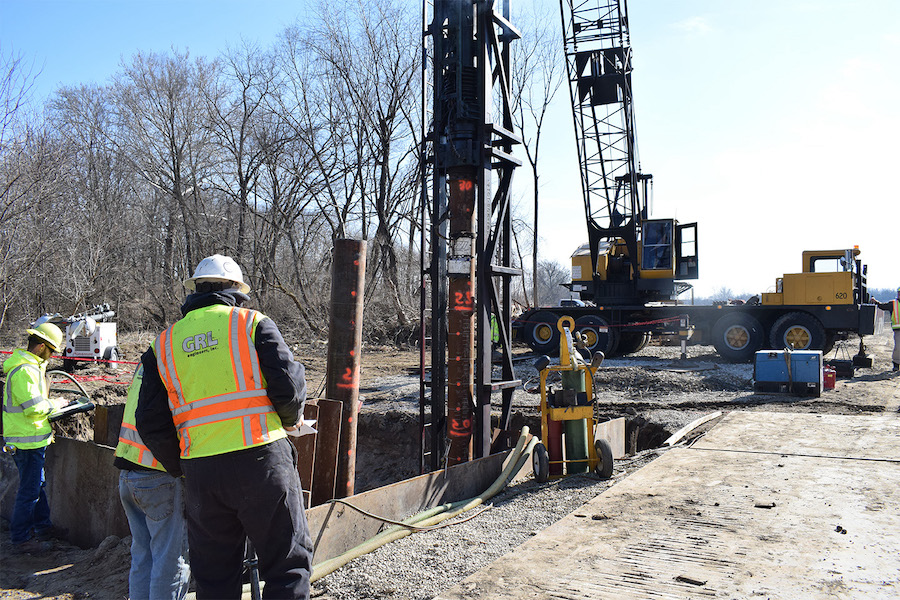
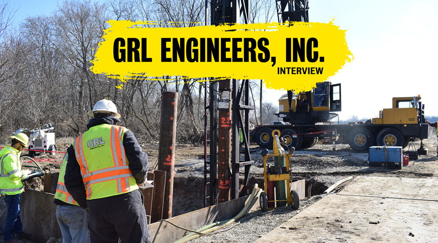
GRL: Piles need to be efficiently installed to their required capacity safely without exceeding the specified allowable driving stress. In some cases, a minimum penetration depth must also be achieved. Dynamic pile monitoring can be performed easily with minimal delay throughout the pile driving process offering an economical test method to facilitate pile installation to satisfy these objectives. Results of pile driving stress, hammer energy/performance, pile integrity and mobilized capacity are evaluated in real time during driving. Driving recommendations can be given to the contractor immediately after testing so pile driving operation can continue without delay.
PB: What’s involved in dynamic pile testing?
GRL: For Driven piles, dynamic monitoring requires attaching strain transducers and accelerometers to the pile. During impact driving, these measurements are converted to force and velocity records that are processed by a Pile Driving Analyzer (PDA). The acquired dynamic monitoring data can be used to estimate bearing capacity during driving with Case Method or iCAP®, or after data collection with CAPWAP® analysis. Compression and tension stress levels monitored during driving are compared to driving stress limits and allow field adjustment to the pile installation procedures if necessary. The dynamic monitoring results also provide information on soil resistance at the time of monitoring as well as on driving system performance. Since Pile Driving Monitoring occurs in real time, it can be performed with minimal delay to the foundation construction. GRL can perform Pile Driving Monitoring by having an engineer at the job site or remotely from the GRL office, using SiteLink®. Dynamic measurements can also be made during installation of vibratory hammer installed piles and sheets to assess installation issues and stresses.
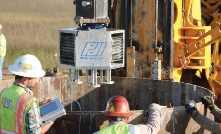
PB: What about Dynamic testing on Drilled shafts?
GRL: A Dynamic Load Test on a drilled shaft requires a suitable ram mass that impacts the top of the shaft. Prior to the test, GRL can recommend an adequate hammer or drop weight size based on the required test capacity to be proven. GRL can mobilize one of its many APPLE Load Testing Systems anywhere in the continental USA. These APPLE systems utilize ram weights ranging from 1 to 80 tons and can mobilize capacities as high as 8,000 tons (16,000 kips). The APPLE system can be assembled in a relatively short time and can easily be moved from shaft to shaft with a crane.
Accelerometers and strain transducers attached to the foundation measure force and velocity as the drop weight applies several impacts (generally 3 to 5 impacts applied one at a time). Instead of strain transducers, GRL may also use a force transducer, which speeds up the test, avoids the need of extending the shaft above ground and in certain cases may yield more accurate force measurements. GRL analyzes data in real time with the Pile Driving Analyzer® (PDA) dynamic testing system. Data is further analyzed with the CAPWAP® software. In addition to bearing capacity, Dynamic Load Testing provides information on resistance distribution (shaft resistance and end bearing) and evaluates the shape and integrity of the foundation element.
PB: Does dynamic pile monitoring delay foundation construction?
GRL: Not in any significant way; The delay is minimal and saves time and money in the long run. Dynamic Load Testing is a fast, reliable and cost-effective method of evaluating foundation bearing capacity. Dynamic load testing can be performed on driven piles, drilled shafts, auger-cast piles, micropiles, helical piles, and other cast in place foundations. It is often possible to conduct several dynamic load tests in a single day.
PB: What other purposes does dynamic pile monitoring serve?
GRL: When dynamic pile monitoring is implemented as part of a test program, it can assist in developing the pile installation criteria, so piles are driven to the required capacity at driving stresses that are below recommended limits to minimize the potential for pile damage. When used during production pile driving, it can check that the pile installation is in accordance with the established criterion and specification requirements.
PB: Is there a load limit where dynamic pile estimate bearing capacity is no longer reliable?
GRL: No not really, we have tested driven piles in the offshore industry in the range of 4,500 tons (9,000 kips). For drilled shafts, GRL’s largest drop weight of 80 tons is capable of mobilizing up to about 8,000 tons (16,000 kips) for a shaft bearing on bedrock. The capacity that can be measured is a function of the hammer size, pile size, and soil type or behavior. The capacity computed from dynamic testing is determined from one-dimensional wave mechanics and how these waves interact with the soil resistance and therefore the accuracy of the test method is not dependent on the magnitude of the soil resistance.
GRL: CAPWAP® analysis uses a rigorous numerical signal matching process to determine the soil model from measured force and velocity records. The CAPWAP analysis procedure yields the mobilized pile capacity including the shaft resistance distribution and toe/base resistance as well as the dynamic soil parameters (quake and damping). Analysis output includes a graphical summary of the analysis results along with numerical tables summarizing the soil resistance versus depth, pile stresses, and the pile model. For driven piles, the CAPWAP determined soil resistance and dynamic soil models are often used to develop GRLWEAP refined wave equation input parameters and establish the pile installation criterion.
PB: What is GRLWEAP Analysis?
GRL: GRLWEAP analysis is a computer simulation of an impact driven pile that is used for both selection of driving equipment and pile selection as well as for bearing capacity assessment. An engineer assembles the pertinent project information including the pile type, pile length, required ultimate capacity, specified driving stress limits, and geotechnical information. With this information, the engineer can then use the program to develop a bearing graph analysis (blow count and stresses versus capacity). The traditional bearing graph analysis provides the computed blow count, hammer stroke, compression stress, and tension stress for a given capacity. This analysis is frequently used to determine an initial pile driving criteria which can then be further refined with Dynamic Load Testing.
PB: It’s also used for driveability analysis, yes?
GRL: GRLWEAP is also routinely used for driveability analyses to assess whether the blow counts and driving stresses will be acceptable for pile installation to the required pile penetration depth and capacity. A summary of the drivability results also includes a predicted driving time for the modeled conditions. These analyses can be used for hammer selection and cost comparison among available hammer options.
PB: What is Thermal Integrity Profiling (TIP)?
GRL: Thermal Integrity Profiling (TIP) is a method of integrity which utilizes the heat generated by the curing process of concrete to evaluate the integrity of drilled shafts and augered cast-in-place (ACIP) piles, micropiles and other concrete foundations such as mass pours. For drilled shafts, this method requires that Thermal Wire® cables be installed to the reinforcing cage prior to concrete placement. For augercast piles, a center bar or cage with Thermal Wire attached is inserted post-grouting.
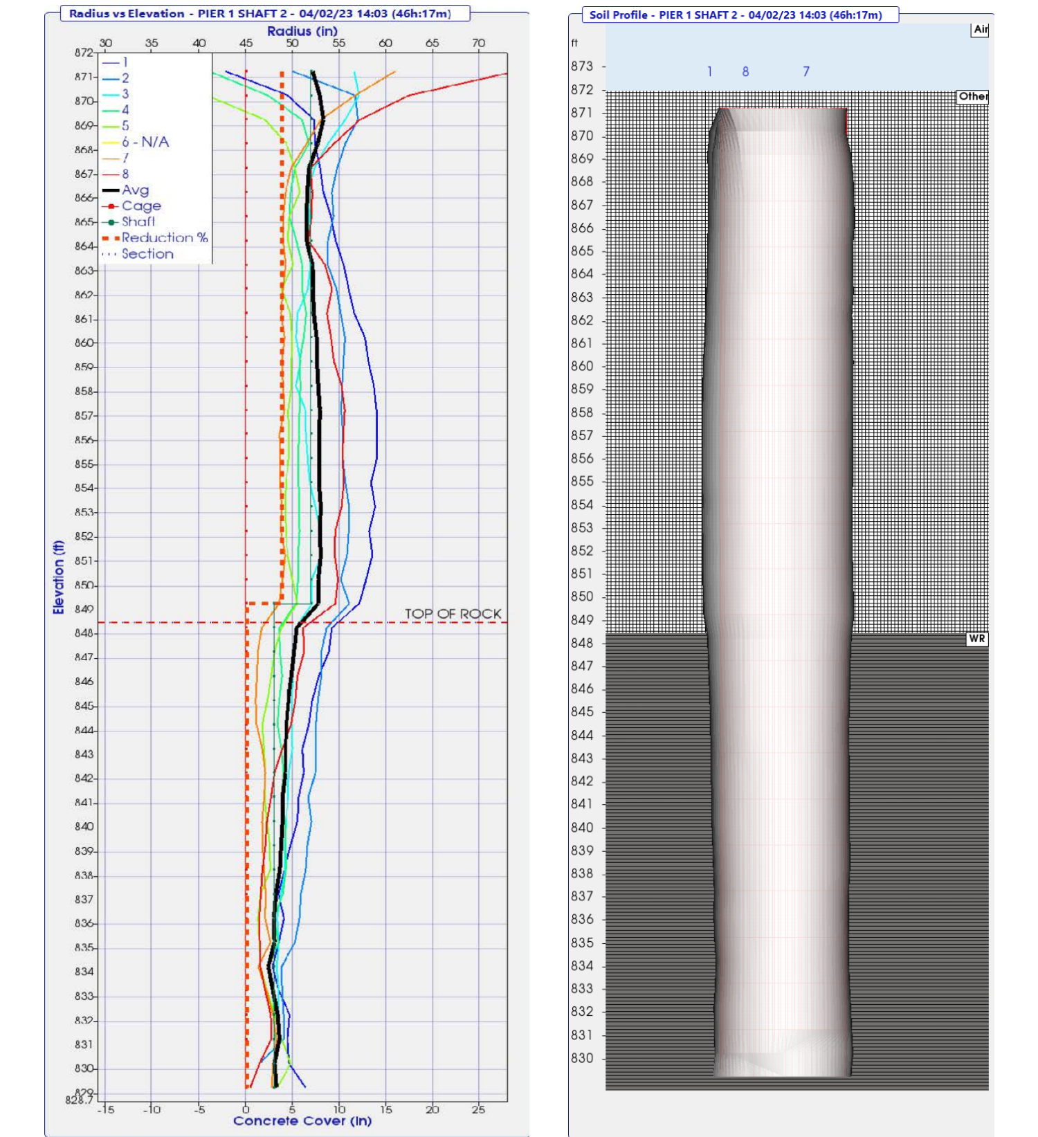
PB: How does TIP work?
GRL: While the concrete or grout is curing, the heat of hydration allows the interpretation of the as-build shape of the shaft and can indicate necks, soil inclusions (regions colder than average), bulges (regions warmer than average), variations in concrete cover, shape of the shaft, and cage alignment. TAG and TAP Edge units collect temperature readings at 15-minute intervals from each wire during the curing process and send the temperature history to the cloud in real time for review and data processing. Final TIP results include plots of the shaft radius and concrete cover versus depth. These results may be evaluated for shaft shape and integrity, concrete quality, and for location of the reinforcing cage. The overall average temperature for all Thermal Wire readings over the embedded depths can be directly related to the overall volume of concrete installed. Figure 1 below shows a typical output graph indicating the computed shaft radius and concrete cover.
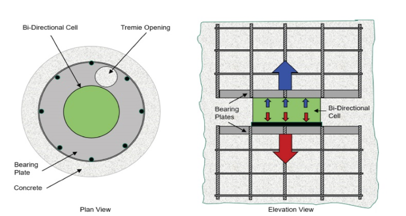
PB: What is Bi-Directional Static Load Testing ?
GRL: A bi-directional static load test (BDSLT) is a test in which a deep foundation element is internally loaded from a specific location along its embedded length. Load is applied by hydraulically pressurizing one or more GRL-Cells, often affixed between upper and lower bearing plates. The GRL-Cells, instrumentation spanning them, and upper and lower bearing plates are collectively referred to as the jack assembly which is cast into the foundation element. The jack assembly simultaneously pushes upward against the shaft resistance above the jack assembly location and downward against the sum of the shaft resistance below the jack assembly location as well as against the foundation elements toe or base resistance (see Figure 2 below).
PB: what information can you get from a BDSLT ?
GRL: Determination of resistance below and above the load cell (end bearing for shaft bearing on bedrock). Optional embedded strain gauges within the foundation determine the soil/rock resistance distribution along the foundation length for optimizing the foundation design.
PB: what are SHAPE and SQUID Testing for Drilled Shafts?
GRL: SHAPE and SQUID are two relatively new testing methods that help the engineer/owner have better quality control during shaft construction.
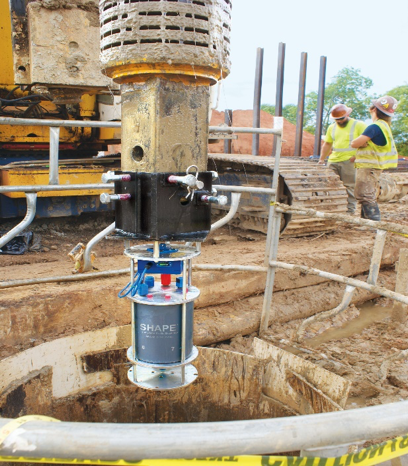
SHAPE Device
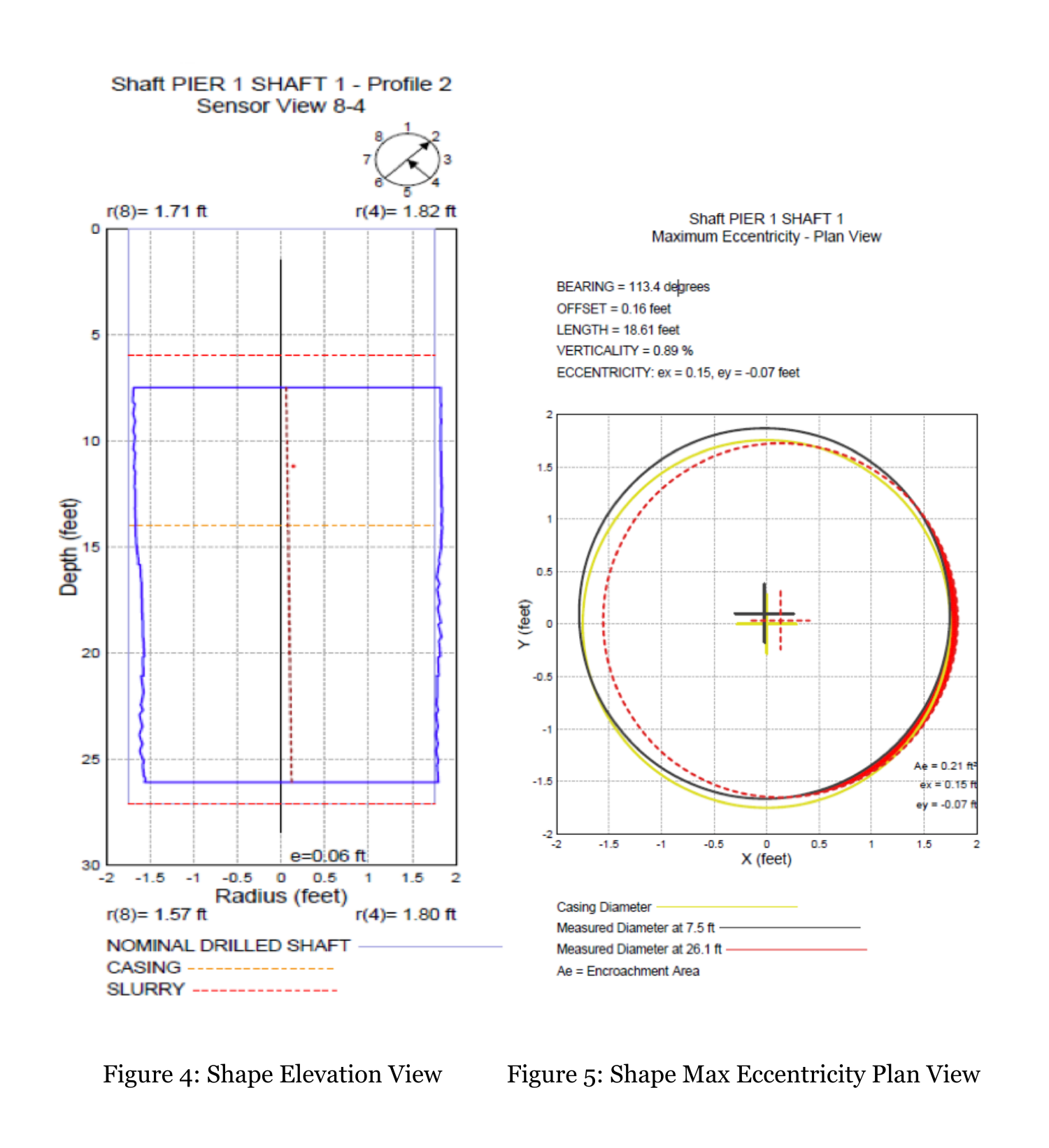
The Shaft Area Profile Evaluator (SHAPE) is used to determine the “shape” of a drilled hole excavation by scanning the sides of an excavated drilled hole to measure drilled verticality, radii, shape, and drilled hole volume. Once the SHAPE device has been quickly connected to a drill rig Kelly bar, it is positioned over the center of the drilled hole (see figure 3). The device is then lowered into the hole while simultaneously collecting data as it is descending or ascending in the drilled hole. Following removal of the SHAPE device from the drilled shaft excavation, the collected test data are downloaded, processed, and displayed. This can be done in real time with a GRL engineer on-site, or it can be done remotely with the engineer connected to the SHAPE Tablet via the internet. Figure 4 shows a typical elevation view from the SHAPE measurement from one of the 4 vertical scans. Figure 5 shows the plan view of the maximum eccentricity along with verticality offset from center.
SQUID Device
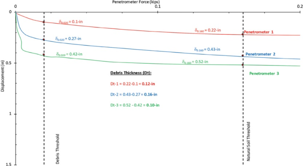
The Shaft Quantitative Inspection Device (SQUID) determines the cleanliness of the bottom of the hole prior to the placement of reinforcement and concrete. The construction process of drilled shafts is carried out using major drilling tools to cut through the soil and rock strata, which consequently generates some amount of soil cuttings, a portion of which could end up at the bottom of the excavation. Furthermore, If the wet construction method is implemented, the drilling mud (polymer-based or bentonite-based) may generate sediments which can accumulate at the bottom of the hole, if undetected can negatively influence the performance of the foundation element. To achieve cleaning once drilling is complete, methods such as a cleanout bucket or airlifting are typically used to remove any material unsuitable for end bearing support. Bottom inspection can be performed by lowering a camera down the bore hole, a procedure that gives a rough idea of the thickness of any debris left at the bottom. To improve the inspection method and speed up the testing, GRL Engineers utilizes SQUID to measure force and displacement at the bottom of a drilled hole to quantitatively assess the cleanliness or the debris thickness of the excavation bottom. The instrumented penetrometers can also provide qualitative information on bedrock hardness. Like the SHAPE device, the SQUID device can be quickly connected to a drill rig Kelly bar and lowered into the drilled hole until it contacts the debris and or rock strata (see figure 6).
Typical output includes a plot of penetrometer displacement versus penetrometer force (see figure 7). The debris thickness is computed from the difference of the displacement at two pre-determined threshold values.
PB: What else should our readers know about GRL Engineers?
GRL: Our professional staff of over 40 civil engineers in our 13 offices are aware of the construction industry’s requirement of immediate response and have at our disposal sufficient personnel and equipment to quickly respond whenever or wherever testing services are required. With our wealth of knowledge, with GRL’s constant desire to keep up with technology and advancements in the testing industry, with GRL’s connection to the industry through paper writing and conference presentations, GRL remains the most experienced and reliable deep foundation testing firm in the world.