Marine Railways / Patent Slips Guide
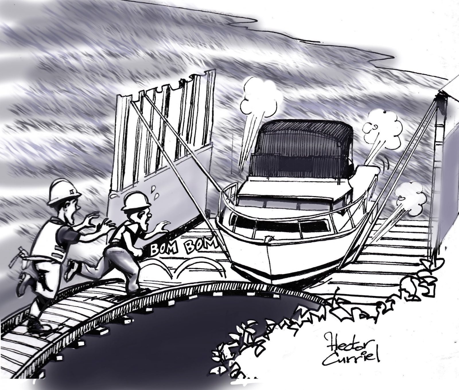

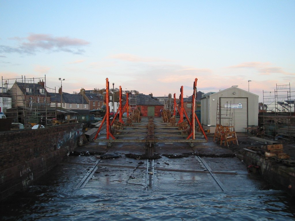
Marine railways, or patent slips, are inclined planes that extend from the shoreline into the water, with a geared hauling machine used to pull vessels out of the water through a combination of horizontal and vertical movements.
Marine railways are a less expensive alternative to dry docks for marine vessel repairs. Because marine railways lift vessels above the water, all working areas around or under the ship have more light and ventilation.
Marine railways are also a fast, convenient and economical method of docking and undocking vessels. They can be utilized for vessels weighing up to 5,000 tons.
Constructing a marine railway requires an understanding of many factors, including how marine railways work, proper site selection, design load and the equipment necessary for a particular railway.
This article outlines the fundamentals of marine railway construction, with special focus on one particular type of marine railway: endhaul railways.
Marine Railway Basics
Marine railways are able to pull the cradle and vessel out of the water by using the mechanical advantages of an inclined plane and geared hauling machinery.
There are two types of marine railways: endhaul and sidehaul.
Both types of marine railways have inclined planes that extend into the water, cradles that move on groundways tracks, wheels that are attached to the cradles or a roller train not attached to the cradle or track, hoisting machinery, and chains or cables for hauling the cradles out of or into the water.
Two Types of Marine Railways
Endhaul marine railways are often favored for many construction projects.
First, they allow for easier pulling equalization than sidehaul railways.
The primary advantage of endhaul railways is that it requires approximately one-third of the valuable waterfront space as a sidehaul marine railway would require. In addition, operation of this type of railway is considered to be safer and less complicated, as a single pull on the centerline of a long, narrow vessel is safer than multiple pulls along the broadside of the same vessel.
Sidehaul marine railways may be required in some situations. For example, for non-tidal riverbanks, a sidehaul railway may be necessary because there is no slack water period to permit docking a vessel at right angles to the current.
In addition, the characteristics of the navigational channel may preclude the vessel from docking at an endhaul facility.
Finally, sidehaul marine railways are useful for hauling cut vessels, such as barges with flat bottoms and shallow draft.
Because endhaul marine railways are used most commonly, this article will primarily focus on the construction of this type of system. Sidehaul marine railways are discussed more succinctly at the end of the article.

Comparison of Docking and Undocking Systems
There are generally three options for docking and undocking boats: marine railways, dry docks and graving docks.
The method chosen will depend on a number of factors, including the type of waterway, the type of work to be performed on the vessels, and the cost.
Generally, marine railways are best adapted to waterways with sloping bottoms.
Groundways for marine railways usually extend several hundred feet beyond existing piers and wharfs, which may present hazards to navigations.
When deep water is available at the bulkhead line, marine railways may be constructed farther inshore, with space included for hauling equipment. Larger marine railways will extend approximately 500 feet inshore.
In contrast, graving docks are more adaptable to shipyard sites and do not extend beyond the bulkhead line. They also provide a uniform water depth, with the vessels docked in a level position.
Notably, marine railways are more susceptible to climate and water changes than graving docks and dry docks.
Working conditions for vessel overhaul are favorable when using a marine railway, as the railway will lift vessels above the water level and allow workers to work in and around the ship.
Graving docks, however, provide more protection against the elements, as well as more convenient working spaces.
The cost of constructing and operating a marine railway is cheaper than building a graving dock or operating a dry dock.
Routine maintenance costs are likely to be similar for each type of dock, although major repairs to marine railways will likely be more expensive due to the difficulty of making underwater repairs.
In terms of time, a marine railway can dock and undock a vessel much faster than through dry docking, and approximately four to six times faster than in a graving dock.
The proper choice of a docking and undocking system will depend on a thorough analysis of each of these factors. While marine railways are often the most cost-efficient system to construct and operate, they are not the best choice for all waterways and conditions.
Selecting a Marine Railway Site
Once it has been determined that a marine railway is the appropriate system for docking and undocking vessels, the next step is to select the appropriate site for the marine railway.
There are five specific requirements that must be met for any marine railway site:
(1) Sheltered harbor
(2) Channel of adequate depth and width
(3) Suitable soil or rock foundation
(4) Satisfactory tidal, current, silting and climatic conditions
(5) Sufficient area and suitable sites for all proposed related facilities.
In addition, the distance from the highwater or bulkhead line to the navigation channel must be adequate for the construction of the railway’s offshore end.
It must also provide a safe fairway for vessels approaching and leaving the marine railway.
Also, there must be sufficient land inshore, including shore frontage, for construction of the groundways and the machinery/hoist house.
The inshore land set aside for the project also must allow for side and end clearances, spur tracks, roadways, cranes and working areas.
The natural characteristics of the water and soil also should be examined when choosing a site.
To avoid excessive silting, which can damage a marine railway, natural bottom slopes along the railway’s offshore end should be lower than the track grade, unless the location is free from alluvial deposits and littoral drift.
The inshore foundation must have soil of sufficient strength to preclude settlement and the proposed location should have natural protection from strong winds and waves.
Finally, piers or dolphins should be provided on the windward sides to facilitate warping vessels into the cradle.
Design Criteria for Endhaul Marine Railways
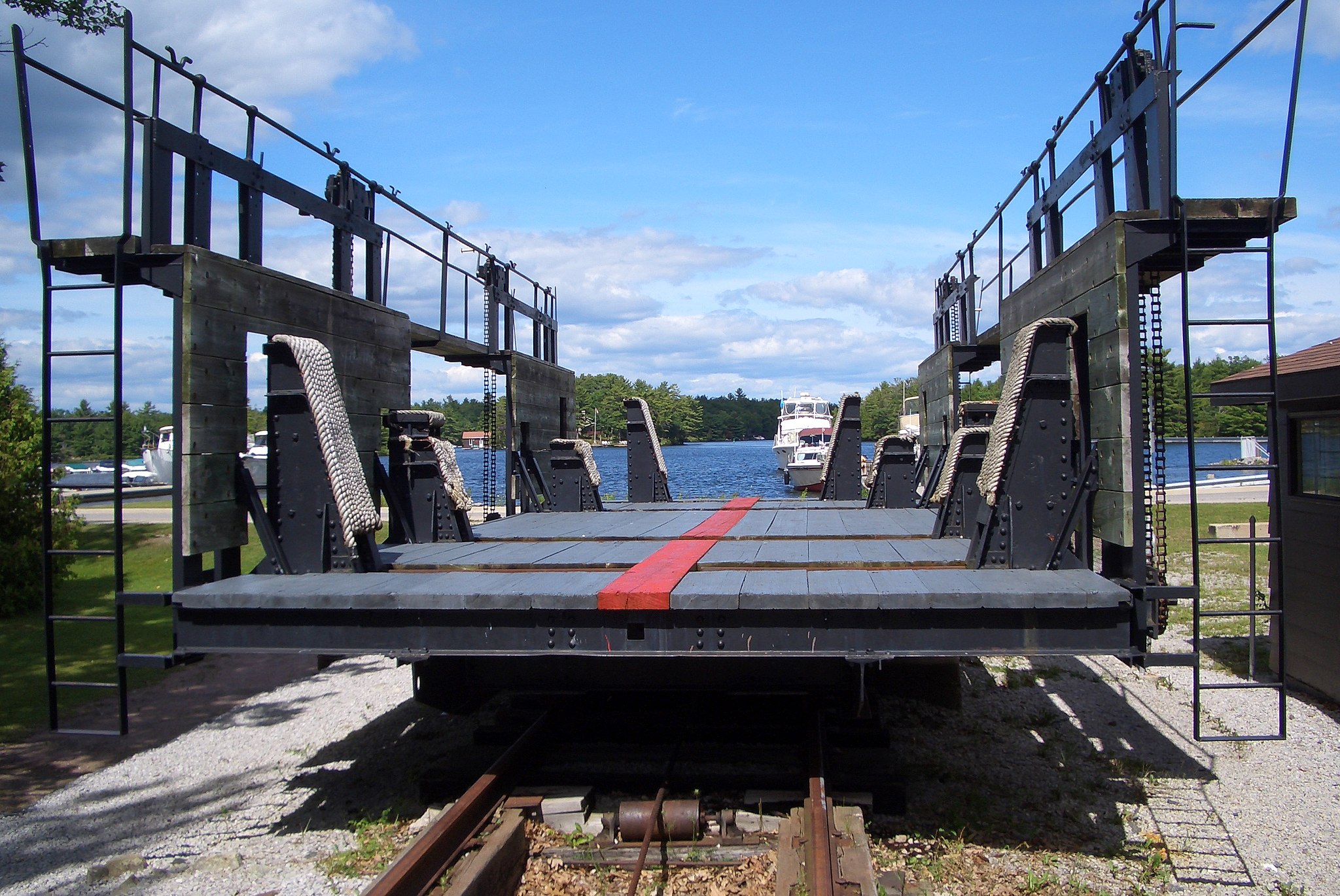
There are three basic components to a marine railway system: a cradle, track and machinery/hoist house.
While the specific design criteria for each component will depend on the particular project, there are some general considerations that should be taken into account for all marine railway construction.
Marine railways are designed for docking vessels at mean high water when the deck of the cradle is entirely dry.
As a result, the vertical cradle rise which must be provided for in-the-track design is the sum of its vertical dimensions.
Large marine railways are typically built with track slopes of either 3/4 or 7/8 per foot.
The height of the blocks at the inshore end of the cradle should be as low as possible to avoid the necessity of high blocks at the offshore end of the cradle.
The length of the track will vary based on whether it is a roller system or wheel system.
For cradles with wheels, the minimum required length is the sum of the distance the cradle must travel to rise the determined vertical height and the length of blocks on cradle.
For roller trains, the length is determined by determining the minimum length of tracks for wheels and adding the length of two roller sections.
The minimum total track length is the minimum track length plus the distance required for necessary clearances and the hoist house. The ideal total track length would add an additional 100 feet inshore to permit hauling the cradle out of the water for inspection and repair.
The machinery or hoist house must contain the hauling machinery. This will include an electric motor, a train of reduction gears, and the wildcat or wire rope drum.
In addition, a clear, paved space should be permitted at the rear of the hoist house to allow for wheeled traffic.
Design Loads of the Marine Railway
When designing a marine railway system, it is vital to understand the load that the railway will be required to hoist and transport.
While the size of the ship may be one factor to consider, most ships that will use the marine railway will likely be in light operating condition. However, because marine railways will sometimes be required to dock and undock ships that are fully loaded, they should be designed to bear these loads.
A crucial aspect of designing a marine railway is considering all types or classes of ships that may be hauled by the system in the future.
Once this data has been obtained, it can be utilized to examine a complete docking cycle with these ships on the cradle blocks.
While some vessels may have a weight equal to the maximum load capacity, an equal weight distribution may put less pressure on the cradle blocks.
In contrast, a ship with a lower weight may have an unequal weight distribution, putting more weight on the offshore blocks than the inshore blocks.
Alternatively, a ship’s weight may be cantilevered over the cradle, with much of its weight on two or three blocks.
All scenarios should be considered so that the facility can accommodate the ships that may be docked there without a breakdown in the system.
Care should be taken to not rely heavily on previous designs, which may not take the characteristics of new ships into consideration, or on designs that are for ships of a different nature (i.e., commercial ships if the railway is intended for Navy ships).
Contractors should also take wind load into consideration when designing and building marine railways.
Wind acting on the side of a docked vessel can put additional pressure on the blocks because of the tendency of the boat to overturn. This factor should be included in the design load calculations.
Finally, contractors should take stability of the vessel on the blocks, as well as the overall stability of the vessel and the cradle, into account.
Characteristics of Clearances of Vessels Using the Marine Railway
One of the most important aspects of designing a marine railway is understanding the type of vessels that will utilize it for docking and undocking. The type of ship that will use the marine railway will ultimately determine the design of the system.
There are ten primary features that must be considered when it comes to vessels that will utilize the marine railway:
(1) Maximum displacement
(2) Maximum overall length
(3) Length on keel (bearing length)
(4) Maximum beam
(5) Maximum draft forward and aft in docking condition
(6) Shape
(7) Weight distribution
(8) Appendages that may extend below the keep line and require special treatment, including propellers, rudders, and sonar domes or other devices
(9) Width of keel bearing
(10) Any damages below the waterline which would interrupt the bearing or structural continuity of the vessel.
Based on these factors, a contractor can determine the length, beam, required draft over the blocks, other characteristics of the cradle and groundways, plus the added working clearances of the marine railway.
Clearance dimensions must be added to vessel dimensions in order to provide working space around and under the ship. Adequate working space is generally 15 feet at each end of the ship and 5 feet at each side of the vessel’s maximum beam.
Track or Groundways
The load bearing capacity of the groundways changes as vessels are docked and undocked. When a vessel is docked, the groundways are supporting the vessel, the cradle and the groundways itself.
When the cradle is hauled offshore, the groundways is subjected to the maximum load per lineal foot until it reaches the point where the effective weight of the ship is reduced by buoyancy. Once the ship is entirely waterborne, the only effective load on the groundways is the cradle and the groundways.
Marine railway tracks and groundways should be designed so that the elevations at the offshore end take into account:
(1) Maximum drafts, forward and aft, of the design vessel
(2) Slope of the track
(3) Slope of blocks on the cradle
(4) Length of the cradle
(5) Height of upper block above track
(6) Depth of water (including one-foot clearance) over blocks at offshore position of the cradle. Optimum design of marine railways should allow docking at mean low water.
Increasingly, marine railways are constructed with tracks that have a vertical curve. These curves offer specific advantages, such as shortening of the horizontal track distance, while increasing the slope of the offshore end, reducing the chain load, reducing excessive dredging, and reducing cradle depth for easer self-docking or maintenance.
Track support is vital to maintain a marine railway.
Tracks are often damaged due to excessive stress or misalignment. This can be avoided by supporting the tracks with piles or concrete slabs on rock, coral or firm soil.
Piles can be made from timber, concrete or steel, and should be fortified with cross struts and horizontal and vertical diagonal bracing as required.
Track stringers should not be placed directly on pile heads, as it will be difficult to drive them into the exact position.
Cross capped pile bents make alignment of the piles less important. Where heavy loads are involved, two-pile bents under each rail can be used to form part of the track bracing system.
Marine railways can be constructed with either two, three or four rails.
Three and four rail tracks have the advantage of offering continuous support under the vessel, but are not as efficient as two track systems.
Whatever number of rails is chosen, chain paths and guides should be constructed between rails made of steel or treated timber.
Cradles can be supported on marine railway tracks in one of two ways: 1) through a system of rollers or 2) a system of wheels.
In a roller system, the rollers are in contact with an upper track on the bottom chord of the cradle as well as a lower track on the top of the groundways.
One disadvantage of this system is that when it is running without a load, obstructions such as silt or driftwood can derail the roller train.
In a wheel system, wheels attach to the cradle and roll on a rail or heavy plate that is part of the groundways. There is less danger of derailment with a wheel system.
Cradles
The cradle is the part of the marine railway where the vessel rests as it is hauled offshore or undocked. Most cradles are designed with steel frames with wood or steel decking.
Timber can be used for smaller capacity designs, although ballast must be used to counteract its buoyancy. When steel cradles are used, they should be designed with few members and heavy sections to reduce the effect of corrosion.
Cradles should be designed for a combination of loads based on the type of vessels that will be using the marine railway.
In addition, the forces of wind and current should be considered as part of the overall design load process.
Marine railways utilize a hoisting system to pull vessels in a cradle to dock. Cradles should be designed to take pulls from hauling chains that are attached to a crossarm.
Contractors should provide both transverse and longitudinal bracing to handle all loading conditions.
Keel and bilge blocks are used in cradles to stabilize vessels and ensure proper load distributions. Depending on the type of vessels to be hauled, keel and bilge blocks should be spaced sufficiently far apart to meet these goals.
Keel blocks should be anchored to prevent potential overturning and cribbed at points of heavy load concentrations.
Elevated timber walkways should be provided on each side of the cradle, along with crosswalk at the inner end.
These walkways should be outfitted with a bilge block hauling mechanism, cleats and chocks, and/or ringbolts of ample size for securing lines.
Uprights along the walkway can form the sides of the cradle and support staging. Fenders should be installed along each inboard side of the walkway structures
Other features that are typically installed on cradles include nonslip steel floors, ladders for access to cradle walkways, bootjacks to line up ships for hauling, and draft gauges to show the depth of water over the end keel block.
In addition, anchors should be installed at the inshore end of the groundways to hold the cradle in the inboard position.
Finally, a motor-operated docking winch may be installed on the centerline of the walkway at the shore end of a marine railway to haul in the vessel.
Machinery and Hauling
A machinery or hoist house is a vital part of a marine railway system. It should be designed as a one-story building with substantial floor area to contain the hauling machinery, switchboard and other equipment.
While the details will vary by project, there are certain general requirements for the construction of a machinery or hoist house. These include:
- It should typically be made of light, noncombustible material unless there are other considerations that justify a more substantial building material.
- It should have windows for light and ventilation, providing a full view of the cradle and groundways.
- An access door should be provided, along with one large door to allow for easy removal of machinery.
- In addition, facilities should be provided to remove machinery. This may include a crane in the building, a removable skylight or hatch over the hoist.
- For the machinery, cast iron guide thimbles should be provided for the bottom of the chains in the sidewalls, along with a steel wearing plate for the top of the chains.
- Machinery pits should be properly sized and drained, with necessary handrails and guards.
The hoists used to lift the vessels out of the water are typically designed and manufactured by a specialty manufacturer, with the requirements determined according to project specifications.
The inhaul chains will pass over wildcats or sprockets mounted on the hoist shaft turned by a gear chain that is directly connected to a hoist motor.
Once the hoist has been manufactured, it should be installed carefully upon a rigid foundation and set in place with anchor bolts of ample size. Misalignment may subject gears, bearings and shafts to over-stress, leading to rapid deterioration.
There are numerous other necessary items that should be included in a machinery/hoist house design. These include:
- Primary control equipment for forward and reverse operation and plugging, as well as secondary control equipment.
- A master control switch should be installed to ensure smooth operation of the railway, along with an emergency control switch to disconnect the control circuit and apply the brakes.
- Overspeed and limit switches can also prevent accidents, along with hydraulic thruster-operated automatic brakes utilizing weights or springs for closing.
Each of these features can help to ensure the safe operation and longevity of the machinery and marine railway itself.
Facilities
The area in and around the marine railway is also important to the overall running of the system. For example, ensuring that there are sanitation facilities that are convenient to the marine railway for the ship’s crew and workmen is critical to the usefulness of the site as a whole.
If the area around the marine railway lacks trucking facilities, installing a standard gauge track along one side of the marine railway can assist with the delivery of materials and equipment via a traveling crane.
Similarly, services can be provided through extensions from shore systems by extending the mains approximately the full length of the cradle in its inboard position, installing service pits to offer fresh water, salt water flushing and fire protection, steam, compressed air, electrical power and lighting.
Dolphins and approach piers may also be necessary to temporarily moor or guide vessels into the cradle due to severe local wind, tide or current conditions. This can be done through piers, dolphin or platforms installed beyond the offshore end of the groundways.
Sidehaul Railways
As noted above, sidehaul railways are similar in design to endhaul railways, but are used less frequently. Typically, two or more cradles are provided to allow for more than one small vessel to be docked independently. When multiple cradles are used, equalization of pulls on inhaul chains is particularly important.
Depending on the number of cradles involved, the control system for a sidehaul marine railway will need to be arranged so that the cradles can be operated together or separately.
The design load must be calculated to take into account the different configuration of vessels that may be placed on these cradles.
A specially-designed electrical system can synchronize the hoisting of the cradles to ensure that the vessels are pulled up with equal speed, even when they have varying loads.
Summary
Marine railways are a cost-efficient method of docking and undocking vessels of all sizes from waterways.
With careful consideration of where the railway will be located and how its various components will be designed, a marine railway can be an optimal solution for public and private organizations seeking a fast and economical method to dock and undock ships for repair.
What are the advantages of using marine railways over dry docks for vessel repairs?
Marine railways offer a less expensive alternative to dry docks, providing improved light and ventilation around the vessel during repairs.
How do endhaul marine railways differ from sidehaul marine railways in terms of construction and usage?
Endhaul marine railways require less waterfront space, are considered safer, and are commonly used, while sidehaul railways are suitable for specific scenarios, such as non-tidal riverbanks and hauling cut vessels.

