


Pile Driving Part III: Installation Equipment


View the complete article here.
Over time, the technology for pile installation has led to the development of hammers that are both larger and faster. From rams that were raised by humans or horses to steam, air, and hydraulic hammers to double acting hammers, this equipment is an essential part of any construction project where piles are necessary.
Hammers play a crucial role in pile installation. Not only do they advance the pile into the ground, but they serve as testing equipment in measuring the pile’s bearing capacity. The way that the hammer interacts with the pile-soil system can be modeled before driving and then monitored during installation to both control driving stresses and estimate load capacity. Field inspections can be performed to make sure that the hammer conforms to minimal standards, and record observations on the hammer and driving system performance.
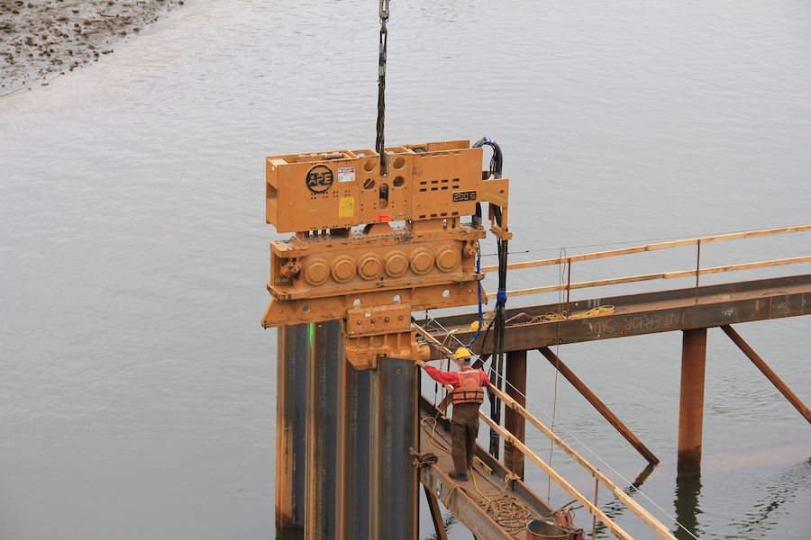
The driving systems used to raise and lower hammers consist of four components: the lead, the hammer cushion, the helmet, and the pile cushion. Each component of the drive system can impact both the performance of the hammer as well as how it transfers its energy to a pile.
Selecting a hammer may be the most crucial aspect of pile installation. On some construction sites, only one type of hammer may be viable for the specific pile-soil combination. For other sites, several types of hammers may be suitable. Contractors must consider factors such as allowable driving stresses, desired penetration rates and other data as defined by project specifications. In addition, the anticipated driving resistance, ultimate capacity, soil set-up, and expected pile stresses during driving should be weighed in making a decision.
In this article, we will outline various types of hammers, serving as a guide for construction professionals as they select hammers for use on a construction project.
Impact Hammers
Impact pile driving hammers contain two main parts: a ram and a mechanism that allows the ram to move quickly upwards before falling down onto the driving system and pile. To move the pile, the ram must have a mass and impact velocity that is sufficiently large. A hammer that is functioning properly will strike the pile in quick succession, transferring a large percentage of the kinetic energy of the ram into the pile.
When the ram hits the pile accessory, it creates a force that is far larger than its weight. If it is sufficiently large, then the pile will move incrementally into the ground. The distance that the ram falls is known as the stroke, and is usually between three and ten feet. If the stroke is too low, the pile will not move into the ground. A stroke that is too high may damage the pile.
External Combustion Hammers
When the fuel that operates the hammer is burned outside of the hammer itself, the piece of equipment is known as an external combustion hammer. This type of hammer have an external source of power, such as the crane that lifts it, a steam boiler, an air compressor, and/or hydraulic power packs. These power sources provide energy to move the ram upward, and in some cases, to move it downward.
Drop Hammers
The drop hammer is the oldest type of pile driving hammer. Most frequently, the hammer is connected to a cable, which is then attached to a winch on the crane. The hammer is raised to the preferred stroke, and then a clutch is released to drop the hammer. The ram falls by its own weight, striking a pile cap and the pile itself. The hoist from the crane then lifts the ram back to the desired stroke. Standard weights for drop hammers are 500 to 10,000 pounds, with drop heights of approximately four feet.
Drop hammers are most often found on very small projects or on small piling. They are simple to use, relatively inexpensive, and easy to mobilize. However, the rate of operation is fairly slow, and driving efficiency depends on the operator’s skill.
One type of drop hammer requires a minimal amount of head room, with a pipe pile that is sufficiently large to allow the pile hammer to move up and down inside of its walls. The hammer impacts on a stop that is built into the bottom, with the impact occurring near the toe of the pile. In this way, the pile is pulled down into position instead of being pushed.
When drop hammers require the ram to unwind the cable from the drum as it falls, the effective energy of the hammer is reduced. An operator may not achieve constant strokes as a result, with variable energy outputs varying from blow to blow.
Single Acting/Steam Hammers
Single acting air/steam hammers are a type of drop hammer, with the hoisting cable replaced by pressurized air or steam (motive fluid). The ram is typically a short block of steel that is connected to a piston at its top. It is guided by columns or inside of guiding enclosures.
For this type of hammer, the maximum available energy per blow is expressed as ram weight times stroke. Ram weights may vary from 3 to 300 kips, with stroke heights from two to five feet. As a result, energy ratings vary from 6 to 1,500 kip-feet.
Single acting air/steam hammers operate at a rate of 35 and 60 blows per minute, which is comparable to most other hammer types without downward assist. Most of these hammers have a fixed stroke. However, the stroke of some hammers may be varied if a dual set of cams and a valve trip is installed on the slide bar. This adjustment is usually performed remotely, using a hydraulic line. The main advantage of variable stroke hammers is their ability to reduce driving stresses during early stages of driving, when the soil resistance is generally lower.
A single acting air/steam hammer operates on a two-step cycle. First, the blow is initiated by introducing the motive fluid at a constant pressure in a cylinder under the piston. As the pressure increases, the ram moves upward. At a certain height, the pressure inlet valve is closed, and the pressure chamber is opened. Second, the ram will coast upwards under its own momentum. At the top of a full stroke, the piston penetrates a safety chamber that has been formed by trapped air, which aids in the deceleration of the piston. As the ram descends, it reaches a position prior to impact where the valve opens to allow motive fluid to enter the cylinder. At the same time, the exhaust is closed.
There are a number of benefits of single acting air/steam hammers. They have a higher rate of blows per minute, compared to drop hammers, with relatively consistent operation. It also consists of a simple hammer design, compared to most other hammers. However, these hammers require additional equipment (such as a boiler, compressor, and hoses) and requires a higher crane and handling equipment capacities due to the weight of the hammer.
Because the air/steam hammer is an external combustion hammer, its performance depends on the boiler or air compressor. This equipment must have enough capacity to provide the necessary operating pressures at the required fluid flow rate. The hammer specifications will require both an operating pressure and an operating volume.
Single acting air/steam hammers should be used with a pile helmet to support the hammer assembly and house the striker plate and hammer cushion if necessary. The correct cushion thickness should be used to ensure proper performance. A cushion that is too thin may cause pre-admission (where the pressurized motive fluid enters the cylinder before the impact occurs, slowing the fall of the ram). A taller cushion stack will shorten the ram stroke, resulting in blows with lower energy.
Double, Differential and Compound Acting Air/Steam Hammers
Double acting air/steam hammers were created to increase productivity through a hammer that applies blows in quick succession. To achieve this goal, the stroke was shortened, and the ram was accelerated during the down stroke through active pressure. These types of hammers work twice as quickly as single-acting hammers. However, energy output is extremely sensitive to proper valve timing, pressure, and volume of the motive fluid. In addition, the applied hammer energy output is sensitive to soil resistance, and the available energy of eeach blow is harder to inspect and verify.
“Double acting” is a term that is often used for any hammer that uses air, steam, or hydraulic pressure to accelerate the ram in the down stroke, along with gravity. A more accurate term may be “downward assist,” as it takes into consideration the various methods by which this goal can be accomplished.
With double acting hammers, the ram has a rigidly connected cam throw (or in some cases, fluid valve) that engages a cam rod that has been suspended in the intermediate head of the hammer. The motive fluid enters the inlet port and flows through the lower opening of the valve to the underside of the piston. From there, the top opening of the valve completes a path from the topside to the exhaust port of the piston. The fluid lifts the piston and the ram, and the lugs of the cam throw slide past the edges of the cam rod until they engage a spiral portion of the cam rod. This causes the cam rod and the valve to rotate, which allows the inlet motive fluid to enter the top of the cylinder and the exhaust fluid to escape through the exhaust port. As the ram falls, its velocity is increased by the fluid pressure on the top of the piston. The cam throw lugs move down, where another spiral portion of the cam rod is engaged. As the cam rod rotates, the valve returns to its initial position and the motive fluid path reverses.
Differential acting hammers are similar to double acting hammers, except that the air or steam is constantly pressurized under the piston. This permits a simpler valve configuration. The cycle begins at impact, with the valve rotated so that the area above the piston can exhaust the compressed air or steam from the previous stroke. The area in the cylinder between the large and small pistons is always pressurized, which creates an unbalanced force on the piston so that the ram accelerates upward. As the ram moves upward, the intake wedge actuates the trip, rotating the valve and admitting steam to the cylinder. This action creates an unbalanced force downward, causing the ram to stop at the top of the stroke. The ram is then forced downward, gaining kinetic energy from both the downward acting steam or air and gravity. Just before impact, the exhaust wedge rotates the valve to exhaust the compressed air or steam, and the cycle starts again.
With compound acting hammers, air or steam is used expansively during the operating cycle, and downward assist is applied to the ram. With this type of hammer, the ram is raised under full pressure, with the upper chamber vented. When the ram reaches the top of the stroke, the upper chamber contains full pressure. The inlet valve closes as the ram descends, allowing the motive fluid to expand in both the upper and lower chambers. A net downward force results because the top ram area is significantly larger than the bottom area. This type of hammer uses motive fluid more economically than double acting hammers.
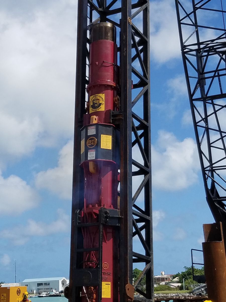
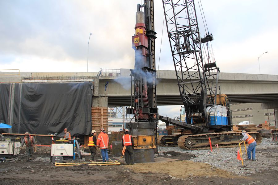
Hydraulic Impact Hammers
Hydraulic impact hammers use an external energy source to lift the hammer to the top of its stroke. For single acting hydraulic hammers, the piston develops actual energy as it free falls. This type of hammer substitutes hydraulic fluid for air or steam, which is applied to the piston to move the ram. A hydraulic power pack provides the necessary energy for the hammer.
Hydraulic impact hammers may be single acting, double acting, differential acting, or another variation. Most of these hammers use an electric valve that is operated with a variable timer. This timer allows for flexible control of output energy. Other hammers use a purely hydraulic system to control the valve and the cycling of the ram, which removes the need for electronics on the hammer. Some hydraulic hammers can be powered using the hydraulic power units on the crane or excavator, so that a power pack is not necessary.
Hydraulic hammers have a variable stroke that can be controlled via a control box. Because the stroke can be varied infinitely, the stroke can be optimized to match the dynamic spring constant of the hammer and pile. Many hydraulic hammers have the ability to induce a single blow, which can be useful in dynamic testing or in severe pile rule. Most hydraulic hammers are efficient because they have some type of downward assist to equalize the hydraulic flow during the hammer cycle.
Jacking
Pile jacking machines advance piles by pushing them into the ground. This type of machine is most effective when the soil resistance is lower than the maximum ram force, and when there are piles for reaction. These machines operate by first placing the jack on the reaction stand for the installation of the first two piles. The jack elevates its travel carriage while supporting itself on the previously installed pile. The travel carriage slides forward, lowers itself, drops onto the installed piles, and then continues its hydraulic insulation process. After the third or fourth pile is driven, the jack then moves off of the reaction stand and travels independently on the piles. Pile jacking machines can be used for sheet and tubular piles.
Internal Combustion Hammers
Internal combustion hammers burn the fuel that powers them inside of the hammer itself. Diesel hammers are the only type of internal combustion hammer, although other fuels may be used. There are two basic types of internal combustion hammers: single acting and double acting.
Single Acting Diesel Hammers
Single acting or open end diesel hammers consist of a long slender piston — the ram — which moves inside of a cylinder. Because the cylinder is open at the top, the ram partially emerges from the cylinder. This type of hammer may be referred to as either open end, because the upper end of the cylinder is open, or as single acting, because the ram falls only under gravity.
Most single acting diesel hammers are built using impact atomization, or liquid fuel injection. The impact block typically has enlarged top and bottom sizes. The cylinder bottom is usually narrowed to just allow free movement. In this way, the impact block can move up and down several inches, but will not fall out of the cylinder when the entire hammer is lifted. Openings in the cylinder walls serve as exhaust ports, with the recoil dampener located between the cylinder bottom and the impact block bottom. The recoil dampener works to cushion the cylinder against a strong upward impact block movement.
There are three stages in an open-ended diesel hammer cycle, starting with the piston being raised to an upper position using the winch of the pile driving rigs or via hydraulics. The piston is then released, and falls down under its own weight. As it falls, the piston pushes the fuel pump level, and fuel from the pump is sent the recesses of the anvil or into the combustion chamber. As the ram passes the exhaust ports, it closes them, compressing the air for combustion. The piston then impacts the anvil, with the energy of the impact vaporizing the fuel and driving the pile. The pile recoils upon impact, pushing the impact block upwards, and causing it to collide with the cylinder. The air-fuel mixture is then ignited, and the piston is raised up, with additional driving impulse transmitted to the pile. As the ram moves upward, the exhaust ports are cleared and excess pressure blows off.
The magnitude of the upward ram velocity is based on the hammer combustion pressure, the stiffness of the hammer and pile cushions, the pile mass and stiffness, and the soil stiffness and/or resistance. Almost all components of the hammer-pile-soil system have an effect on the diesel hammer’s stroke, with the ram stroke increasing as pile driving becomes harder in normal conditions. If a soil has high resistance but low stiffness, the stroke will be relatively low.
Single acting diesel hammers do not require additional equipment, making them a cost-efficient solution. As strokes increase in hard driving, the energies increase. Low strokes in easy driving will protect concrete piles. In addition, the ram has a relatively low weight compared to the energy that it provides. However, the stroke of this type of hammer is dependent on a hammer-pile-soil system. With high strokes, there are relatively low blow rates. Finally, there is a potential for environmental issues with this type of hammer.
There are two main questions to consider when determining the performance of a single acting diesel hammer. First, the stroke of the hammer must be adequate for the situation. Second, the energy output at a given stroke must be adequate. The stroke can be measured in a number of ways, such as by attaching a jump stick or by using a Saximeter, which measures the period between blows got calculate the ram stroke. There are a number of reasons why the stroke output may be insufficient, from a soft driving system, long flexible piles and spongy soils to lack of fuel, improper fuel, lack of compression, and excessive friction. Each of these issues should be thoroughly evaluated to determine what may be causing poor stroke output.
Double Acting Diesel Hammers
A double acting or closed end diesel hammer consists of a slender piston (ram) that moves inside of a cylinder. Unlike a single acting/open end diesel hammer, the top of this cylinder is closed, which causes the ram to compress the air that is trapped between the ram and the top of the cylinder. When the ram falls, it is subject to both gravity and the pressure in this chamber.
There are eight major parts in a double acting diesel hammer: (1) a piston or ram with piston rings; (2) an impact block with rings; (3) a cylinder; (4) one or more fuel pumps; (5) fuel injectors; (6) exhaust ports; (7) recoil dampener; and (8) a bounce chamber with exhaust ports. These ports are opening in the cylinder wall. The impact block usually has a larger top and bottom diameter, while the cylinder bottom has a diameter that is just large enough to allow free movement. In this way, the impact block can move up and down, but will not fall out of the cylinder when the ram is raised. The recoil dampener serves to cushion the cylinder against a strong upward impact block movement from pile rebound, and is located between the cylinder bottom and the impact block bottom.
The primary advantage of a double acting diesel hammer is that it is a self-contained unit that does not require additional equipment. It also has a high blow rate compared to open-ended diesel hammers. However, there is significant uplift in hard driving, as well as uncertain energy when combustion prevents ram-anvil impact. For this reason, the stroke is not easily determined with double acting diesel hammers. This type of hammer also has more complex maintenance requirements as compared to other types of hammers.
To operate a double acting diesel hammer, the ram is lifted above the exhaust ports through a tripping device and a hoist or a hydraulic jack. As the ram rises, it closes the bounce chamber ports, and air is compressed inside of the upper bounce chamber. When the ram reaches the starting height, the trip is released and the ram falls under both gravity and the pressure from the air in the bounce chamber. As it passes the exhaust ports, the ports close and a volume of air is trapped inside of the chamber. The ram compresses this trapped air, which becomes hot.
Once the ram reaches a certain position, it pushes a lever and plunger system into the fuel pump, which then injects fuel into the chamber. For impact atomization systems, the fuel is then injected into the chamber in a liquid form, and combustion will not occur before the ram hits the impact block. For atomized fuel injection, combustion takes place shortly after the fuel is injected, as long as the air in the cylinder is sufficiently hot. The combustion lasts as long as the injection.
At impact, the ram forces the impact block, hammer cushion, helmet and pile head downward, which allows the cylinder to fall under gravity. The impact block then separates from the ram within a short time period, with the pressure of the combustion causing further separation. Depending on the length of the pile, the pile will rebound, pushing the impact block upward. The impact block hits the cylinder, with the upward moving ram eventually clearing the exhaust ports (potentially after a second impact). Excess pressure is blown off, and the ram continues upward.
The magnitude of ram velocity with this type of hammer depends on the pile mass and stiffness, the hammer and combustion pressure, the stiffness of the hammer and pile cushions, soil stiffness and/or resistance, and the rate at which the pressure in the bounce house increases. Each component of the system can affect the diesel hammer’s stroke. In normal conditions, the ram stroke will increase as pile driving becomes more difficult. However, soils that have high resistance and low stiffness may result in a relatively low stroke.
Diesel Hammer Fuel Systems
There are two types of fuel systems used with diesel hammers: liquid fuel injection and atomized fuel injection. Liquid fuel injection may also be referred to as low-pressure injection or impact atomization. In this process, the ram compresses the air in the compression chamber as it falls. Fuel is then injected, with liquid forming on top of the impact block. The impact of the ram disperses the fuel, mixing it with the hot compressed air, and combustion takes place.
With a cool hammer, combustion may start within two milliseconds after impact. However, as the hammer heats up, the fuel will start to evaporate as soon as it is injected, with combustion starting without delay. The hotter that a hammer is, the more likely it is that there will be an early combustion. A hammer that is overheated may cause pre-ignition, with combustion well advanced by the time of impact.
With atomized feel injection hammers, fuel is injected under high pressure into a cylinder that is filled with hot, compressed air. This high pressure injection causes the fuel to enter the chamber as a fine mist. The fuel will burn as soon as it enters the hot air. This fuel is injected when the ram reaches a specific distance from the impact block. Injection and/or combustion end after the ram reaches a certain point during rebound.
When driving is easy, combustion will begin independently of the speed between the ram and impact block. Because the ram is falling slowly, with a short stroke, the time between the start of combustion and impact will be longer, allowing the combustion pressure to develop sufficiently to stop the ram before impact — with little energy transferred to the pile.
Atomized fuel injection hammers work well if they are perfectly maintained. The fuel injection timing must be accurate to the millisecond. If there are any damaged parts, such as worn injectors or fuel pump parts, performance may be affected significantly.
Driving Accessories
The striking end of a ram cannot directly adapt itself to all pile shapes. For this reason, accessories must be inserted to mate the hammer and the pile and to transmit the force of the impact hammer to the pile. These accessories include hammer cushions, anvils, helmets, pile cushions, mandrels, and followers.
Hammer cushions receive the first striking energy of the hammer, and are necessary to protect the hammer’s striking parts from damage. They may be made of wire rope biscuits or steel cloth plates, micarta and aluminum, hamortex, blue nylon, plywood, or end grain hardwood. A softener cushion will produce a longer impulse with a lower maximum force, while a harder cushion will produce a shorter impulse with a higher maximum force. The hammer cushion is usually installed at the top of the helmet in a pot shaped recess, with a striker plate on top to protect the hammer cushion. Hammer cushions have a limited life, as they compress over time. A broken, burnt, or overly thin hammer cushion will be inefficient. For some hammers, such as certain diesel and hydraulic equipment, a hammer cushion is not necessary.
Anvils are necessary for internal combustion hammers, in order to trap the combustible mixture and to allow it to build pressure. They are not used in external combustion hammers.
The helmet is a heavy, rigid steel block that is located between the hammer and the pile. It serves to distribute the blow from the hammer in a more uniform manner across the head of the pile to minimize damage to the pile. The striking surface of the helmet should be smooth and contact the top of the pile evenly, with no more than 2 inches of lateral movement allowed. The weight of the helmet is determined based on the drivability of the pile using the wave equation.
If a helmet is poorly seated, stresses at the pile top may develop. It may also lead the exposed portion of a long pile to buckle under each blow of the hammer. Two piece driving helmets may be used with diesel hammers, which do not hit the pile with the same intensity of air/steam hammers.
For driving concrete piles, a pile cushion will be required. Plywood is the most common pile cushion material in the United States, although hardwood may be used with the grain perpendicular to the pile axis. Whatever material is used, it should be both dry and unburned. When it begins to burn, it should be replaced. After roughly 1,000 blows, the cushion may become compressed and too hard. In these situations, the cushion should be replaced.
Mandrels are used to install thin-wall shell piles before they are filled with concrete. This accessory is necessary because the walls of the pile are too thin to withstand the stresses of driving. Mandrels may be stepped, tapered, or expanding based on the configuration of the pile. If a mandrel is used with a shell of uniform diameter, they should be expandable to tightly grip the pile and prevent collapse. Mandrels must be able to resist hammer blows and to transmit energy to the bottom of the pile while distributing forces along corrugations.
Most mandrels have corrugations to match the shell, and are referred to as the segmental leaf type. These mandrels are expanded by mechanical, pneumatic or hydraulic forces to grip the shell tightly and protect against deformation and tearing.
Finally, followers are steel members that are place between the pile hammer and the pile itself. A follower allows the pile to be driven beyond the reach of the leads. They are most commonly used for driving piles over water or to drive a pile below the top of an existing structure. While followers can make driving easier, it can be difficult to maintain alignment between the pile and the follower, and misalignment can make it difficult to equate blow count with pile capacity. For many projects, specifications exclude the use of followers.
Vibratory Drivers
Vibratory drivers are machines that install piling by applying a rapidly alternating force to the material. It is usually accomplished by rotating eccentric weights about shafts. Each of these rotating weights produces forces that act in a single plane, directed towards the centerline of the shaft. The weights are set off center of the axis of rotation by the eccentric arm. These arms are paired to avoid a lateral whipping effect, leaving axial forced for the pile. Depending on the driver, there may be several pairs of small identical eccentric arms or one larger pair.
Most vibratory hammers have mass that does not vibrate with the rotation of the eccentrics. The mass is like a downward pull from a crane, and can help the driving process. Some models also have additional weights to add to the suspension system. A good suspension system will minimize boom vibration while providing a shock-free location to attach hoses or cables.
Vibratory hammers work by loosening the soil surrounding a pile so that the pile penetrates the ground through a combination of its own weight and the static force generated by or through the suspension system. When the soil lacks cohesion, the upward force creates a fluid effect on the soil or sand. With cohesive soils, this effect may be enhanced by thixotropy, where the soil is turned into a gel by a reversible chemical process. The elevation of pore water pressures in both types of soils also help the piles to penetrate the soil.
Vibratory driving is an effective method for installing piles, with the biggest obstacle being toe resistance of the pile. Sheet and H-piles, which have small toe areas, are the best-suited to vibratory driving.
Types of Vibratory Drivers
There are five main types of vibratory hammers: low-frequency hammers, medium-frequency hammers, high-frequency hammers, sonic or resonant hammers, and impact-vibration hammers. Low-frequency hammers have a vibratory frequency of five to 10 Hz. They are [primarily used with piles that have both high mass and toe resistance, such as concrete and large steel pipe piles. These hammers often have large eccentric movements to achieve dynamic force.
Medium-frequency hammers use a vibratory frequency of ten to thirty Hz. They are often used for sheet piles and small pipe piles. Most vibratory hammers in use today are medium-frequency, since they use enough dynamic force to excite the soil, the right frequency to interact with most soils, and enough amplitude to penetrate hard subsurface layers.
High-frequency hammers include all vibratory hammers that vibrate at frequencies over thirty Hz. Hammers that operate in the thirty to forty Hz range are used to minimize vibration to neighboring structures.
Sonic or resonant hammers induce a resonant response in the pile, which makes it easier to drive and extract the pile. These hammers operate in a frequency of ninety to 120 Hz. These machines are mechanically complex, which has limited its use.
Impact-vibration hammers are a type of vibratory pile driver that provides both vibrations and impacts to the pile. It has counter-rotating eccentrics that impart vertical vibrations, which are regulated by a set of springs that are linked to the frame. The springs then transmit their compression force to the pile. The head may also strike the anvil to product an impact similar to that of a traditional impact hammer, but with a higher blow rate. These hammers are not manufactured in the United States, are have limited use.
Types of Pile Driven with Vibratory Hammers
Vibratory hammers may be used to drive a range of piles. They can also be used as extractors, to limit noise, as a probe, or to increase mobility. This type of hammer can also reduce pile damage.
Vibratory hammers are often used for sheet piling. The sheeting wall is set in place with a template, and then the piles are driven. In many cases, the sheets are driven two at a time, using a jaw with two sets of teeth and a recess that can accommodate the interlock. Alternatively, the sheet piling may be set as it is driven, in which case the sheets are driven one at a time.
These hammers may also be used to drive H-piles in a similar way. However, if the piles’ batter is large, the hammer may be mounted on a set of leaders, as with impact hammers. Vibrated H-piles may also be used for soldier beams and in slurry wall construction.
Caissons and pile piles may also be installed using a vibratory hammer. This application is particularly successful when installing large diameter caissons and open end pipes that are wide enough so that a pipe does not build up in the end of the pile. A caisson beam can be used to affix the pile to the hammer on opposite ends, with the clamps locked to the slide during use. These clamps can be moved around the horizontal slide to drive a range of pile sizes. Once a caisson has been installed, the material is removed from inside of it, the reinforcement cage is placed, and the concrete is poured to fill the pipe. A vibratory hammer is a cost-saving measure in this use because the pipe can be extracted, leaving a concrete pile o the appropriate size. With conventional methods, concrete overage may be as much as 25%. For pipe piles, the equipment set-up is similar. Generally, vibratory hammers are used for open-ended pipes, as these tools are less effective with closed-end pipes.
Displacement piles, including timber, precast concrete, concrete sheet piling, and closed-end pipes may also be installed with a vibratory hammer, depending on the size of the piles. The larger the displaced volume, the less effective the vibratory hammer will be. Vibratory hammers are rarely used for these types of piles because other methods, such as impact driving, are typically better.
Excavator-Mounted Vibratory Hammers
Excavator mounted vibratory hammers have several distinct advantages over crane-mounted units. With this type of hammer, there is no need for a separate power pack, and the hammer is easier to use in low headroom or indoor sites. The vibrator can be positioned more precisely for both installation and extraction. This set up tends to be lower cost, and easier to move. Finally, down crossing improves drivability without heavy bias weights on the suspension.
Vibratory hammers are typically connected to the exactor boom with a swivel connection. The bucket is then removed from the boom, and the vibrator is mounted. Importantly, because each excavator is different, the mounting must be properly matched, with all connections secure. The suspension capacity must also be adequate for the boom pulling capacity.
With an excavator-mounted unit, there is generally no need for a separate power pack (as with a crane-mounted unit). Instead, the bucket circuit on the excavator can be used to both turn the eccentrics and operate the clamp. This can make an excavator-mounted vibratory hammer a more economical choice.
These units can be mounted in a number of special configurations. A swiveled vibratory hammer can be used for certain types of steel sheet piling, allowing the hammer to rotate 90 degrees and clamp onto the sheets without the need to maneuver the boom. When sheets are set before driving, this type of configuration is unnecessary. Similarly, this typeof set up should not be used with aluminum, vinyl, or pultruded fiberglass sheets.
A gooseneck will lengthen the boom on the excavator, which allows the hammer to be used in a wider range of positions. However, because the boom is longer, greater care must be exercised to avoid turning over the excavator.
Rigs
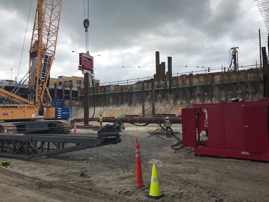
Every pile driver will require a rig to lift the hammer and pile, and to guide the driving system as the pile is driven. In most cases, the rig consists of a crawler crane that has pile driving attachments added, which may include leaders, hammer, spotter, boiler, and/or a moonbeam. The choice of a rig configuration depends on availability.
Cranes for Impact Hammers
Aside from the hammer itself, the crane is the single most important part of a pile driving system. Properly choosing a crane is critical for safe, economical, and correct installation of piling.
A basic crane consists of two crawlers, which distribute the weight of the driver to the ground, along with a car body, and a cab. Each crawler is attached to the car body, and consists of a belt of pants that are connected by pins, rollers that transfer the weight to the pads, and chain-driven sprockets that propel the machine. The operator can apply power to the crawler or lock a crawler in order to steer the machine. On some cranes, the crawlers can be set at a wider distance to provide stability, and then retracted for shipping.
A number of optional features may be added to a crane to make it more suitable for pile driving. This may include an additional reversing shaft and gearing to allow for independent swing and travel, an independent boom hoist, one or two additional drum shades, wide crawler pads to reduce ground pressure, and gantry lifting and counterweight removal devices.
To convert a crane to a pile driver, modifications are necessary. A heavy boom should be used to rest torque and lateral load, such as a Raymond-type boom. A spotter should be installed to the front of the turntable to hold the bottom of the leaders at a distance from the crane. A boiler or air compressor will also be necessary, with sufficient counterweight removed to balance and attach the power unit. For hydraulic hammers, drills, spotters or moonbeams, a hydraulic power pack must be mounted, along with necessary control valves, piping, and hose.
Cranes normally have a capacity of 75% of the load required to tup the machine, with a rating that is based on the maximum load that the crane can pick up at a twelve foot radius with the shortest boom. However, these capacities do not have much value when it comes to choosing a crane for pile driving. A crane capacity chart for pile driving should be used, with ground stability the most important consideration for driver operation. Truck cranes are rarely used as pile drivers, as they usually have very poor capacity for weight when in a position for pile driving.
Booms for Impact Hammers
Raymond-type booms reduce the torsion and side thrust that occur in pile-driving operations. All Raymond-type booms have a basic length of forty feet, with a lower section designed to fit a particular crane and an upper section that may be used on different machines. These booms can be lengthened by inserting sections in multiples of eight feet.
These booms have built-in steam or hydraulic lines, and have racks to store the boom connection bolts. They are generally stronger than most commercial booms, they are not always the best choice in all circumstances. Commercial booms are better suited for driving plumb and in- and out- batter piles, but should never be used for driving side batter piles.
Cranes for Vibratory Hammers
Vibratory hammers are usually free hanging from cranes, rather than operated in leaders. As such, cranes used for vibratory hammers must have adequate capacity to lift the hammer and pile, along with any extraction load when piles are extracted. IN addition, the boom must be able to withstand any residual vibration that is transmitted to it by the suspension.
Power Systems
All external combustion hammers and most vibratory hammers require a power source, depending on the nature of the hammer. Air/steam hammers are usually powered by air compressors. These may be mounted on the ground or on the back of the crane as a counterweight. A three-way shut-off valve should be used to blow pressure out of the lines after the hammer has stopped, or for emergencies. A line oiler to provide a continuous feed of atomized oil to the cylinder should also be installed.
Hydraulic systems are used on pile driving projects with vibratory hammers, hydraulic impact hammers, augers and drills, and spotters and pile monkeys. A basic power pack contains all of the components that are necessary to control the hydraulic equipment and to provide sufficient power. In some situations, the crane’s hydraulic system can be used to power a smaller vibratory hammer or a hydraulic impact hammer, which eliminates the need for an external power pack.
Most hydraulic problems are caused by the poor condition of the hydraulic oil. As such, the proper grade and type of oil must be used. A good hydraulic fluid should be anti-corrosive, stable at high temperatures and fluid at low temps, and be able to lubricate all parts of the system. In some hydraulic systems, engine crank case oils are used. However, the detergents and dispersant additives in this type of oil, along with the cost, make them less than ideal for this application. Turbine grade oils can also be used, but they lack the additives that are needed in severe conditions. Instead, a premium grade, anti-wear hydraulic oil should be used. This oil should contain oxidation inhibitors so that they can be used at higher temperatures without breaking down, along with rust inhibitors, anti-foam agents, and anti-wear additives.
Hydraulic pumps are connected to the engine through a pump drive. These pumps are generally driven by a diesel engine, and are either the low pressure gear type or the high pressure piston type. These pumps are precision made with very small clearances. Their efficiency depends on absolute cleanliness, with damage possible with just a small amount of dirt or dust. High quality filters should be installed to remove particles, and changed once a month.
Leader Systems
To properly align the impact hammer and pile during driving, leader systems are necessary. The configuration of these systems depends on the application.
Fixed leaders are attached via a mechanical joint at the boom point, as well as at the bottom of the leaders. At the boom point, the connection should allow the leaders to rotate around the boom point. A typical fixed leader includes a main section attached at the boom point, a top section, a bottom section, and enough middle sections to obtain the required height. There should be more leaders below the boom tip than above. Spotters for fixed leaders may be manual, moonbeam, or hydraulic, depending on the needs of the project.
Vertical travel or semi-fixed leaders are fixed leaders that have hydraulic spotters than can move the leaders up and down. They are best used when it is exceptionally difficult to position the leaders, as in railroad construction.
Swinging leaders are suspended from the crane using a wire rope, and are the most commonly used type of leader. Because leaders have some freedom of lateral movement, it is necessary to take extra steps to ensure that the piles are properly aligned when they are driven.
Underhung leaders are similar to fixed leaders, but the boom point connection is made at the top of the leaders. In addition, the leader can usually only move fore and aft from the crane. This type of leader is used with or without a spotter.
Although most impact hammers require a leader in order to operate, some hammers can be outfitted with pants. However, this should only be done in accordance with manufacturer recommendations.
For offshore piles, a special type of leader must be used. These leaders are suspended from the cranes, ands the pile to properly align the hammer. This system may also be used for large pipe and concrete cylinder piles in onshore construction.
There are a range of accessories that may be used with leaders, including a cradle or extension when the hammer is too small or large for the leaders used. A pile gate can be utilized to guide the pile into the leaders and keep it in alignment during driving. These may open manually or hydraulically operated. A stabbing point is used with swinging leaders in order to fix the lower end of the leaders.
Specialized Operations and Equipment
Pile foundations are driven in a wide range of conditions. As a result, specialized operations and equipment may be necessary.
Jetting
Jetting uses pressurized fluid to loosen the bond between he pile and soil. This reduces the resistance of the pile to penetrating the ground. Jetting also reduces driving stresses, saves time, decreases vibration and allows for increased pile penetration. After jetting is completed, piles should be driven to their final penetration depth.
This technique is least effective in clay and coarse gravel, but highly effective in fine sands. In clay soils, the jets may become plugged, while in fine grained soils, jetting may loosen the soil around the piles that have already been driven. For this reason, jetting applications may be limited in this situations. It is most often used when displacement-type piles must penetrate strata of dense, cohesion less soils (other than coarse or loose gravel). Jetting can reduce structural damage to piles caused by overdriving.
The process of jetting is relatively straightforward, with water pumped at high pressure through pipes that are attached internally or externally to the pile. A minimum of five to ten feet of pile penetration should be accomplished without jetting. If a pile cannot be driven the final five to ten feet without jetting, the project design criteria may not have been satisfied. It should be avoided close to existing structure or piles.
There are two types of jets that may be used. Fixed jets are a permanent part of the pile. This is a costly option, but may be necessary is a moveable jet cannot be used. Moveable jets are attached to the pile in a way that allows for their removal after the pile has been installed. Two jets located symmetrically provide the most rapid penetration and best control of the pile pipes.
A jetting system consists of jet pipes, a nozzle, pump, engine and hoses. This equipment must be able to produce the desired volume of water at the necessary pressure. Both water volume and pressure must be sufficient so that discharged water can surface along the sides of the pile.
The typical procedure for jetting includes making a hole using a jet of water at the pile location before driving. The pile is then lubricated by the water as it is driven. Because the pile will tend to walk toward the jet, jetting one side then the other may be necessary, or using multiple jets.
Underwater Driving
Although most pile driving in the water can be accomplished from the surface, there are often advantages to driving pile underwater. This process eliminates the use of pile followers to add weight to the system, the use of longer than necessary piles, and the need to cut off piles underwater. Hydraulic hammers are the best choice for this work, as they can be used in very deep water with the power pack on the barge deck and the hoses extended into the water. Hydraulic vibratory hammers may also be used underwater, provided that the water does not seep into the case. For depths greater than forty feet, the motor shaft seals must be protected.
Pre-Excavation
Pre-excavation may be necessary to penetrate upper hard layers of soil, prevent soil heave, reduce driving resistance, to relieve back pressure, or to minimize the impact of driving on adjacent structures. It may also be used to minimize stress on piles and cores and to help remove or displace obstructions. One of the main problems associated with pre-excavation is the disposal of water and soil. The responsibility for this task should be understood before work is started.
Preboring involves drilling, augering, or coring a hole in the ground, and then either filling that hole with concrete or driving a pile into it. This is usually accomplished with a continuous flight auger, although a soil auger or drill may be used if jetting is impractical. Predrilling may be necessary to drive a pile through obstructions, and may also be used for placing piles in embankments that contain boulders.
The hole should be sized so that it is large enough to allow for driving, but small enough to firmly and solidly support the pile against lateral movement. In most cases, the predrilled hole diameter should be four inches less than the diagonal of steel-H piling or square piling, and one inch less than the diameter of round piling. However, if the piling must penetrate very hard material, then the predrilled diameter may need to be equal to that of the pile.
Augering is effective in clay-like soils. It involves the use of a continuous flight auger with a drilling bit that is driven by a hydraulic or air-powered drill. It is at its most efficient when the material is cut up and brought to the surface by the flights. If the auger screws itself into the ground and stalls, the drill should be reversed to bring the auger out of the ground. Augering can be facilitated by adding water, steam or air through the drill stem to lubricate the soil and help to break up the soil and carry it to the surface.
Wet rotary drilling can be used to drill very deep holes where the auger’s power would be excessive. It is well suited for plastic soils that would otherwise stick to auger flights, and for those soils that would collapse unless the hole is filled with fluid. It involves using a drill stem with water supplied through the stem under pressure. This keeps the hole open and carries the excavated material to the surface. The resulting slurry must be disposed of properly.
Rotary drilling involves a carriage mounted hydraulic drill or an open center rotary table. This can be used to drill soft rock. The proper bit for this work will depend on the properties of the rock to be drilled.
Dry pre-excavation involves removing a plug of earth using an open-ended tube. This tube is driven into the ground with a valve on the top. After the tube is inserted, the valve is closed and the tube is extracted. The vacuum created by this system helps to keep the plug of earth in the tube. Steam or air pressure is then used to push the earth plug out. This method can be used in plastic soils to a limited depth. The tube should not be inserted so deep that it is stuck, or so that the plug is too long to be expelled.
Spudding can be used to penetrate obstructions at ten to fifteen feet below pile cut-off elevation that cannot be removed by excavation. The process involves driving a spud (such as a mandrel), a heavy steel pipe or a H-pile section in order to create a pilot hole. The spud is then removed, and then the pile is inserted and driven to depth. If the spud is driven too deep, extraction may become difficult.
Airlifts and air jets may be used in place of water jetting to clean open-ended piles and for other applications. The air acts like water jets would, breaking up compacted materials and carrying it to the surface. This method requires large volumes of air. An airlift involves lowering a conductor pile to the bottom of the pile. A mixture of air and water is then forced upward, with the water carrying the soil with it.
Screw piles involve fitting a pile casing with one or more turns of a helical screw with a larger diameter than the pile. By screwing the casing into the ground to a predetermined level, driving can be more easily accomplished. Pull down is a type of pile jacking where pile casings are jacked into place and then filled with concrete.
Finally, concrete pile cutting is done when the driving of a concrete pile has been completed. This is necessary when the concrete head of a pile must be cut off to expose a reinforcing bar or cable for connection of the pile and the structure. Concrete pile can be cut manually, with jackhammers, or automatically using hydraulic devices called concrete pile cutters.
The equipment used to install foundation piles is critical to the overall success of the project. By selecting the right equipment, you will be better able to meet the design criteria and specifications for the project.
View the complete article here.
How External Combustion Hammers work?
When the fuel that operates the hammer is burned outside of the hammer itself, the piece of equipment is known as an external combustion hammer. This type of hammer have an external source of power, such as the crane that lifts it, a steam boiler, an air compressor, and/or hydraulic power packs. These power sources provide energy to move the ram upward, and in some cases, to move it downward.
What is a Drop Hammer?
The drop hammer is the oldest type of pile driving hammer. Most frequently, the hammer is connected to a cable, which is then attached to a winch on the crane. The hammer is raised to the preferred stroke, and then a clutch is released to drop the hammer. The ram falls by its own weight, striking a pile cap and the pile itself.