Drilled Shafts Guide: Casings & Liners
View the complete article here.
When constructing drilled shafts, casing and liners are vital to the overall success of the project. As such, contractors must pay careful attention to the selection and use of liners and casings, particularly if they are to be used to support drilled shaft excavation or as a structural element of a completed drilled shaft.
Casings are tubes that are relatively strong and are typically made of steel. If joining is required, it is typically done by welding or bolting.
Some casings may have special joints that permit torque and axial loads to be transferred to the tip, such as those that are used with full-depth casing machines.
Liners are comparatively light in weight and become a permanent part of the foundation. They are usually made of corrugated sheet metal pipe (CMP), but can also be made of plastic or pressed fibers, such as Sonotube. While liners are not used as frequently as casings, liners are critical in certain construction projects.
This article will discuss the two main types of casings and liners that may be used in drilled shaft construction: temporary and permanent.
The type of casing or liner that is used will depend on a number of factors, as described in depth below.
Temporary Casings
As the name implies, temporary casings are used during the construction of drilled shafts and then removed afterwards.
Specifically, they are used to stabilize the drilled shaft excavation and then removed either after or during the placement of fluid concrete.
Because this type of casing is functionally a tool, it is sometimes referred to as “temporary top casing.”
It is utilized to retain the sides of the borehole just long enough for the fluid concrete to be placed to a level sufficient to withstand ground and groundwater pressures. It is then removed, with additional concrete placed as it is pulled to maintain the pressure balance.
The fluid pressure of the concrete is then relied upon to provide borehole stability.
If approved by an engineer, temporary casing used to support drilled shaft excavation may be left in place. The engineer must assess the impact of the casing on the axial and lateral resistance of the completed drilled shaft prior to approving this measure.
After each use, temporary casings must be cleaned thoroughly to ensure low shearing resistance to the movement of fluid concrete. If the casings have rough interior surfaces, the shearing resistance between the casing and the column of fluid concrete placed inside of the casing will be increased.
When the casing is lifted, the drag on the column of concrete may cause the concrete to be lifted. This can create a neck or a void in the concrete.
Before installing a temporary casing, contractors should be sure that it is free of soil, lubricants and other materials.

Types and Dimensions of Temporary Casings
Most drilling contractors maintain a large supply of temporary casings of various diameters and lengths. These casings can typically be welded or cut to suit the requirements of a particular project.
In situations where the temporary casing must be seated into an impervious foundation, such as rock, the casing may be used as a tool, with twisting or driving forces applied through it. The end of the casing may then be equipped with cutting teeth or additional thickness in order to enable it to perform its function.
The International Association of Foundation Drilling has adopted the outside diameter (O.D.) of casing as a standard and utilizes traditional units (such as 36-inch O.D.) because it is available used, at a much lower cost than specially rolled pipe with specified inside diameters.
While pipe of a specific size can be ordered, this is typically much more expensive and requires additional time for fabrication.
Standard O.D. sizes are generally available in six-inch increments ranging from 18 inches up to 120 inches.
As a general rule, if temporary casing size is not specified, most contractors will use a casing with an O.D. six inches larger than the specific drilled shaft diameter below the casing.
This allows for the passage of a drilling tool of the proper diameter during final excavation of the borehole.
If there is a boulder field or the contractor needs to use telescoping casing, the first casing that is set may have an O.D. that is more than six inches larger than the specified shaft diameter.
Most steel casing has a wall thickness of at least 0.325 inches, with larger casings (48-inch O.D. and higher) having greater wall thickness.
Casings installed with vibratory or impact hammers often require greater wall thickness. If workers are required to enter an excavation, the temporary or permanent casing should be designed to have an appropriate safety factor against collapse.
Determining the amount of lateral pressure that a temporary casing can withstand is complex. It involves ensuring that the casing will not buckle due to external soil and water pressure.
Contractors must consider a number of factors, including, diameter, wall thickness, out-of-roundness, corrosion, minor defects, combined stresses, microseismic events, instability of soil on slopes, and other sources of non-uniform lateral pressure and lateral pressure that increases with depth.
Semi-rigid liners can be used for linters or temporary casings that may be left of place. These semi-rigid liners can be made of corrugated sheet metal, plain sheet metal, or pressed fiber.
Alternatively, plastic tubes or tubes made of other material may be used. These liners are most frequently used for surface casing where it is necessary to prevent unstable surface soil from collapsing into the fluid concrete, where it could create structural defects.
This often is necessary in situations where the concrete cutoff elevation is below working grade. Rigid liners, such as sections of precast concrete pipe, may also be used effectively for this purpose.
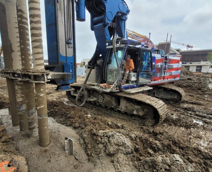
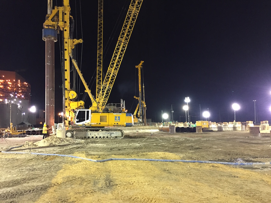
Rotators and or oscillators with segmental casing are being used with more frequency to advance large diameter, deep drilled shafts.
The casing penetration is advanced ahead of the excavation, which allows it to provide support for the excavation and eliminates the need for slurry for side wall stability. However, slurry or water may still be required to prevent base heave.
In these constructions, soil can be removed within the casing using claim, hammer-grab or rotary tools. The casing is usually high strength, double-wall steel, with flush-fitting joints between segments. This allows transmission of torque, compression and tension between casing sections.
Installation and Extraction of Temporary Casings
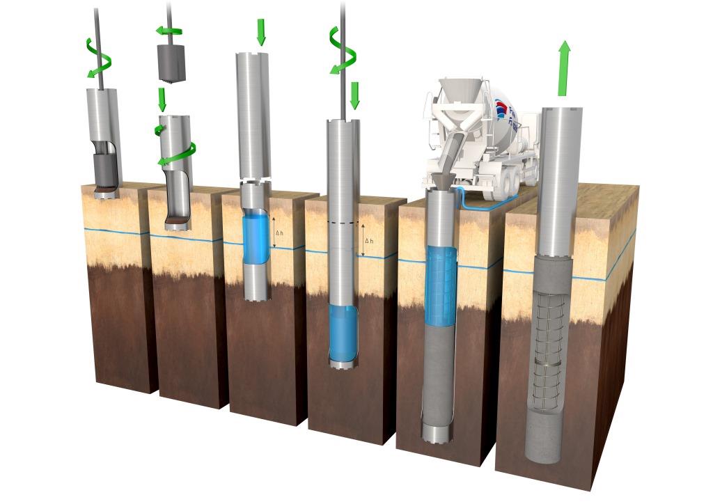
Temporary casing is often placed into an oversized drilled hole and then seated into the underlying formation to provide a stable environment. It also can be advanced ahead of the excavation.
The two primary methods of installation and extraction are discussed below, (1) casing seated through drilled hole and (2) casing advanced ahead of excavation.
Temporary Casings Seated Through Drilled Holes
To seat casings into an underlying formation of more stable material, temporary casings can be placed through a pre-drilled hole.
This pre-formed hole can either be constructed using a wet method involving drilling slurry, or without a drilling fluid if the soil will stand for a short period.
The latter method may be used in areas where the shaft can be drilled fairly quickly through a residual soil to rock and the rock excavation is facilitated by having a temporary casing to prevent cave-ins of the soil.
If the shallow strata include water-bearing sands, it may be necessary to drill the starter hole with a slurry to prevent caving. Contractors also may choose to use polymer slurry to lubricate the casing and make it easier to remove.
The excavation below the casing may also be advanced as a dry hole if the casing is seated with a watertight seal into a relatively impermeable underlying formation of clay, chalk or rock.
To seal the casing, a twister bar attachment to the Kelly bar may be used so that the drill rig can apply torque and crowd to the casing and advance it into the soil or rock.
The end of the casing may be equipped with cutting teeth. Various types of cutting teeth are available based on the type of material into which the casing is advanced.
Pointed rock teeth or welded-on carbide chips are two options.
If the rock surface is steeply-sloping or highly irregular, or if the rock contains seams or joints that allow water inflow below the casing, obtaining a good seal or casing into the underlying rock can be challenging.
In addition, an irregular hard surface can make the casing deflect off alignment, break cutting teeth or even bend.
For deep excavations, some contractors may utilize the telescope casing process, using more than one piece of casing. This process is often more economical, as smaller cranes and ancillary equipment than would be required for a single piece of casing can often be used to install and remove telescoping equipment
A borehole with a larger diameter than is specified is made at the surface then a section of casing is inserted.
A second borehole is excavated below that section, which is then supported with another section of casing of smaller diameter. This often may proceed through three or more progressively smaller casings, with the diameter of the lowest casing being equal or greater than the specified diameter of the drilled shaft.
The O.D. of a lower section of telescoping casing is usually at least six inches smaller than the O.D. of the section above it.
The telescoping casing procedure is most often used for filled shafts that are bearing on or socketed into rock, and where no skin friction is considered in the soils or rock that is cased.
The contractor must take care that removing the smaller sections does not disturb the larger sections of casing that are still in place.
Care also must be taken not to deposit water, slurry, or debris behind casings, as this could contaminate the fluid concrete.
Telescoping casing may also be used in boulder fields, where such boulders are removed and the casing is screwed ahead to refusal. In this process, the smaller inner casing is advanced through the first casing, which retains the zone where the larger boulders were removed.
Temporary Casings Advanced Ahead of Excavation
In excavations where the hole will not stand open for short periods, or where slurry drilling techniques are considered less attractive due to cost or performance, a contractor may decide to advance temporary casings ahead of excavation. There are two primary methods of doing so: using a vibratory hammer, or using oscillator/rotator equipment.
Vibro-Driven Temporary Casings
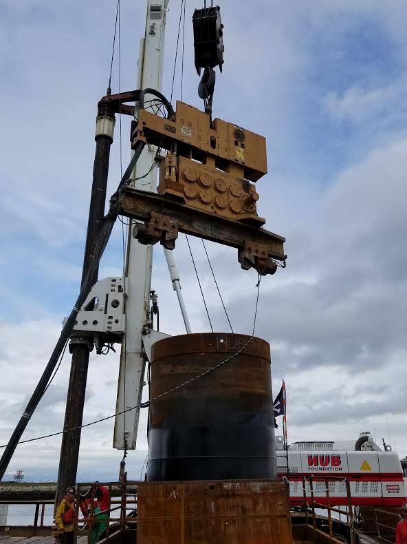
For driven casing, a vibratory hammer is most often used for temporary casing.
While an impact hammer can be used to install permanent casing, this method can make removal of the casing difficult to impossible.
For this reason, temporary casing will require a vibratory hammer for extraction. In theory, jetting could be used around casing to aid installation, but this process cannot be used during extraction, as the jet water would adversely affect the fluid concrete.
Generally, a vibratory hammer is used to place the full length of temporary casing into soil before excavating soil inside of the casing. However, if the soil is particularly dense, the casing can be installed through alternating driving and drilling to remove the soil plug within the casing.
If this is done, it would typically be necessary to install the casing in sections.
Using vibratory hammers to install drilled shafts in congested areas requires significant planning, as these hammers can cause vibrations that may affect nearby structures or cause settlements in loose sands. The impact of the vibrations will depend on the size of the hammer and the casing, the operating frequency of the hammer, the soil and rock properties, the localized stratigraphy, groundwater, and other site-specific factors.
In most construction sites, vibrations from casing installations are limited to 50- to 70-feet from the source. If sensitive structures are located nearby, a vibration monitoring program should be implemented and included in the installation plan. This can help to avoid potential damage as well as provided protection against lawsuits or claims of damage.
Continuous monitoring during construction can provide measurements of vibrations at various radial distances from the source before work is moved into production locations.
The use of a vibratory hammer to install casing is most effective in sandy soil deposits and in penetrating through sandy soils into a clay or marl stratum below.
The hammer clamps to the top of the casing, which is typically reinforced with extra thickness at the end to aid in resisting the transmitted forces. The vibration often causes temporary liquefaction of a thin layer of soil immediately next to the casing wall, so penetration is achieved only with the weight of the casing and the hammer.
Penetration of an underlying hard layer may be difficult or impossible with a vitro-driven casing due to the side resistance of the soil against the casing after the removal of the vibration.
Casings that are installed with a vibratory hammer must be removed while the concrete is still fluid. During extraction, the hammer is attached, and then used to drive the casing downward a few inches to break the casing free from the soil. The crane can then pull the casing upward to remove it, leaving the hole filled with fluid concrete behind.
Oscillator/Rotator Method for Temporary Casings
Installing temporary casing in advance of excavation can also be performed with a drill using special casing and tools through the oscillator/rotator method.
The oscillator or rotator is clamped onto the casing with hydraulic jaws. Hydraulic pistons are then used to twist the casing and push it downward, causing it to react against a large drilling machine or temporary frame.
The casing must have cutting teeth that are slightly larger than the outside dimension of the casing in order to advance the casing and overcome the soil shearing resistance to twisting.
The bottom section of casing is fitted with a cutting shoe to promote penetration and to relieve stress against the sides of the casing. As the casing is installed, the soil on the interior of the casing is removed simultaneously to reduce resistance.
While the casing is installed, a plug of soil must remain inside the casing to maintain the stability of the bottom of the excavation.
In water-bearing soils, the head of water inside of the casing must also be maintained to avoid bottom heave. Slurry can be used inside the casing to maintain stability, but the need for a slurry can be avoided by maintaining a soil plug.
Once excavation has been completed, the soil plug may be removed to the base of the casing, if it is extended into a rock or a stable formation, or if a slurry head is used to maintain stability.
If the hole ends in water-bearing soil with only a water head for stability, the casing may need to extend below the base of the final excavation to avoid instability at the base. Doing so may ultimately result in an annular zone of loosened soil at the base of the excavation.
During extraction, even if the casing was continuously rotated during installation, the casing is often oscillated back-and-forth to avoid potential torsional deformation of reinforcement.
The casing is usually extracted simultaneously with the concrete pour. A concrete head above the tip of the casing must be maintained so that a positive concrete pressure is provided against the hole.
If exterior groundwater pressure is present, the head of concrete and water inside of the casing must exceed the exterior water pressure to prevent the concrete from being contaminated by water.
The concrete also must remain fluid during the excavating so the oscillating casing does not transfer twisting forces and cause distortion.
Potential Effects of Temporary Casing on Axial and Lateral Resistance
When using temporary casing in construction, the impact on axial and lateral resistance of drilled shafts should be considered. As a general rule, regardless of the method of installation, there is not a negative effect on the lateral resistance of a drilled shaft if a temporary casing is removed.
However, the axial resistance may be affected by the method of casing installation.
For drilled shaft holes that derive their axial resistance from the soil or rock below the temporary casing, there is little concern about the adverse effects of the casing on load transfer in side resistance.
When designing a drilled shaft using temporary casing, contractors should consider how much axial resistance is contributed by the temporary casing as compared to the drilled shaft below the casing.
If the contribution of the casing is relatively small, then it is both appropriate and cost-effective to ignore the axial resistance of the casing and use the most cost-effective strategy to install the drilled shaft.
If the side resistance provided by the temporary casing is significant, then contractors must consider a number of factors.
First, casing installed into a predrilled hole may impact side resistance within the cased portion of the shaft if contaminants, debris or loosened soil are trapped behind the casing and left between the concrete and native soil or rock. They can become trapped if a thick slurry is used and left in the annular space behind the casing, or debris may fall into the annular space.
This type of debris is likely to collect in these spaces in temporary casing installed into rock through a predrilled hole; as a result, a good concrete-rock bond will not develop.
In sand, casing advanced ahead of the shaft excavation using a vibratory hammer should not have an adverse effect. It may even have a beneficial effect by densifying the sand around the drilled shaft.
However, casing that has been installed into and then extracted from a cohesive soil using a vibratory hammer may result in a smooth surface and a rough drilled hole.
Using the oscillator/rotator system is generally considered to have no impact on side shearing resistance as long as a stable excavation is maintained.
Using cutting teeth on the bottom of the casing and the oscillation of the casing during withdrawal can leave a rough surface texture of the drilled shaft that can lead to reasonably good unit side shear.
However, a failure to maintain stability at the base of excavation when using the oscillator/rotator system can lead to a loosening of the soil around the shaft excavation that can ultimately lead to a reduction of side resistance.
If the temporary casing extends below the final bottom of the drilled shaft, an annular zone of loosened soil may result in slightly reduced base resistance unless corrected by base grouting beneath the completed drilled shaft.
If temporary casing is installed and cannot be extracted, then an engineer must determine what the impact of the casing on the axial resistance of the drilled shaft will be.
Load-testing methods may be useful in evaluating side resistance around casings. While it is generally not possible to state whether the strength will be increased or decreased by leaving the casings in place, studies have shown that load transfers are significantly lower when casings are left in place as opposed to when concrete is in contact with the soil.
If a temporary casing cannot be removed and has a void around it, it is recommended that the void be filled with grout to ensure transfer of lateral soil resistance around the shaft and to increase lateral stiffness of the shaft.
Removing Temporary Casing After Concrete Sets
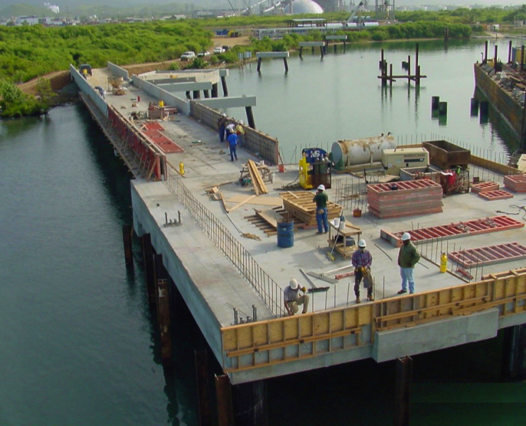
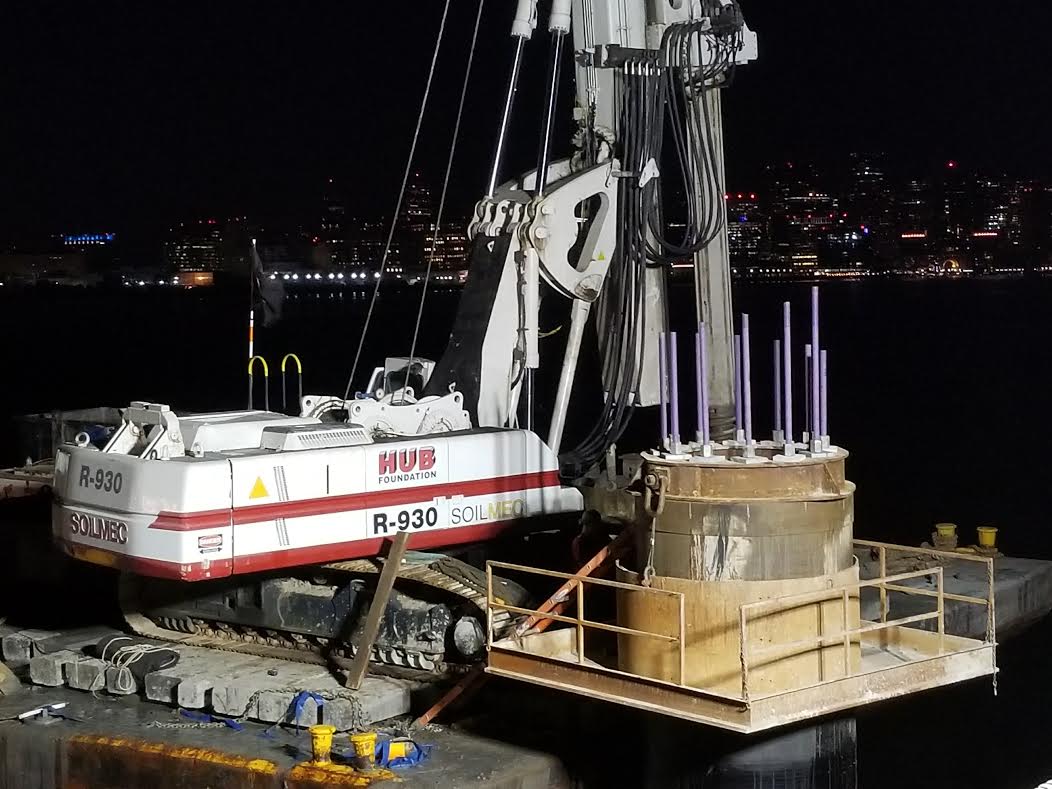
Drilled shafts that are installed through a body of water most often use permanent casings that serve as a form until the concrete sets. Then, these casings are left permanently in place, with portions above the ground or the water removed once the concrete has reached sufficient strength.
However, temporary casings have also been used for similar applications, including removable forms attached to the top of permanent casings.
There have been many reports of difficulties in using temporary casings over water.
Using temporary casings over water presents several problems.
First, after the casing is initially used, the joint is typically not water tight even after it has been cleaned and repaired.
Second, it is often difficult to open split joints, potentially due to the joint being fouled with concrete.
Third, it can be challenging to lift the casing off of the drilled shaft even with a vibratory hammer.
Fourth, when the casing is removed, there may be surface defects on the drilled shaft, such as washouts of cement along portions of the drilled shaft adjacent to the split joint, bleed water cavities and spalls and locally exposed steel reinforcement.
Fifth, costly underwater remediation is often required to fix any defects.
For these reasons, the use of removable casings in offshore foundations should generally be avoided.
As an alternative, temporary casings that are large enough to serve as a cofferdam could be used.
The drilled shaft constructed through the temporary casing may include a permanent casing, or may be constructed using a drilling fluid in an uncased hole.
The concrete placement can be accomplished below the water surface, with a removable form placed inside to form the column and splice the column reinforcement to the drilled shaft reinforcement. In this way, the removable form is not subject to the various stresses associated with temporary casings and the concrete within the form can be placed in the dry after removal of laitance at the cold joint.
After the column form is removed, the temporary casing extending above the top of the shaft cutoff can be removed by divers.
Permanent Casings
Unlike temporary casings, permanent casings are designed to become a permanent part of a foundation.
This type of casing is often used when a drilled shaft must be installed through the water and the protruding portion of the permanent casing is used as a form.
Permanent casing is also used in situations where concrete must be placed in a deep, large-diameter, high-capacity drilled shaft in sound rock. In these cases, pouring concrete may take several hours, such that the concrete may be starting to set by the time that temporary casing is removed.
Permanent casing is often specified in those construction projects.
Permanent casing may also be required where a drilled shaft must pass through a cavity. The casing becomes a form that prevents the concrete from flowing into the cavity.
Using a concrete form can not only prevent the loss of concrete, but it can prevent the mixing of soil or water in the drilled shaft that can produce a void in the structure.
Permanent casing is also used frequently for drilled shafts that extend through very soft soils to reach a more stable underlying stratum. The permanent casing prevents the outward bulging of the fluid concrete into the surrounding soft soils. This prevents the risk of defects in the concrete or a deformation of the reinforcement cage.
Types and Dimensions of Permanent Casings
Permanent steel casings are similar in type and dimension to temporary casings. However, because permanent casing does not need to be extracted, longer sections of pipe may be driven into place.
Additionally, if the casing is to be used as a structural component of a construction project, then the dimensions, properties and welds are subject to quality control and documentation.
For permanent liners, corrugated metal pipe (CMP) is often used, particularly at shallow depths. CMP is relatively flexible and cannot be subject to installation stresses as conventional thicker walled steel pipe.
A semi-rigid liner can also be used to minimize friction from downdrag or expansive soils.
Coatings with low skin friction, such as bitumen, can also be used.
Liners made of two concentric pressed-fiber tubes separated by a thin coating of asphalt have been found to be effective in significantly reducing skin friction in drilled shafts in expansive soils.
Flexible liners are used less frequently in the United States, but can be important in certain constructions. They can include plastic sheets, rubber-coated membranes, or a mesh.
The rebar cage can be encased in the flexible liner before being placed in a dry or dewatered hole, then the concrete is placed inside with a tremie. This is designed to present the loss of concrete into a cavity or to prevent caving soil from falling around the rebar cage.
As friction in the region of the liner cannot be accurately computed, flexible liners are only used in drilled shafts where the resistance is developed entirely below the level of the liner.
Installation and Extraction of Permanent Casings
Permanent steel casing can be installed in the same manner as temporary casing, including seating through drilled hole, advancing ahead of excavation, vitro-driven casing, or using the oscillator/rotator method. It also can be driven into place using an impact hammer.
Permanent casing installed into an oversized hole can be advanced into a rock formation by twisting or driving. If there is a resulting void or annular space, it is generally necessary to fill it with tremie grout to provide lateral soil resistance. This may be unnecessary if the soil is subject to scour or is neglected for lateral loading.
Installation of permanent casings by driving can be highly effective and efficient, as the casing will not need to be extracted. Using an impact hammer to drive a large steel pipe does subject the pipe to driving stresses and requires consideration of drivability.
There are limitations on the ability to drive large diameter steel pipe into hard soils, rocks, or boulders because doing so can result in deformation of the casing preventing the drill tools from passing. If site conditions include rocks, hard soil or boulders, placement of a permanent casing into a drilled hole or the use of a reduced length casing with slurry below the casing should be considered.
Potential Effects of Permanent Casing on Axial and Lateral Resistance
If the soil within the zone around the casing is scoured or is otherwise not able to provide a significant contribution to the design, then the resistance of the soil should not be considered part of the design.
The method of installing the casing is not important to this analysis. However, if the soil in the cased zone will provide a significant contribution to axial resistance, then the casing should be installed so as to provide good load transfer through side resistance.
Installing casings into an oversized hole will generally not provide axial load transfer.
Even if there is no reliance on the soil around the casing for axial resistance, there may be other factors related to the use of an oversized hole for a permanent casing.
If lateral resistance is required, the annular space around the outside of the casing should be filled with grout. In addition to increasing lateral resistance, an unfilled oversized hole can lead to unintended seepage. Filling it with grout can help prevent problems due to water.
Driving casting into place using an impact hammer generally provides similar axial side resistance to that of a driven steel pipe. However, if permanent casing is vibrated into place, the axial resistance of the casing is typically lower than that of an impact-driven casing.
A permanent casing can contribute to the structural capacity and bending stiffness of the drilled shaft. Because over time, corrosion can decrease the thickness of the steel casing, this should be considered when determining the impact of the steel casing on structural capacity. When casings are in contact with fill soils, contractors should consider the specific properties of the fill, natural soil and ground water.
Conclusion
Casings are an integral part of the construction of drilled shafts. Whether they are temporary casings used for supporting the shaft through unstable or water-bearing soil layers, or permanent casings used as a concrete form or as a structural component of the completed drilled shaft, casings and accompanying linings are often necessary to effectively and efficiently construct a drilled shaft.
The method used for installing the temporary or permanent casing, as the removal of temporary casing, can have a significant impact on the strength and stability of the shaft itself. That is why it is vital for every contractor planning a drilled shaft construction project to familiarize himself or herself with the fundamentals of casings and liners.
View the complete article here.
What are temporary casings?
As the name implies, temporary casings are used during the construction of drilled shafts and then removed afterwards. Specifically, they are used to stabilize the drilled shaft excavation and then removed either after or during the placement of fluid concrete.
How many methods are there for installation and extraction of temporary casings?
There are 2. (1) casing seated through drilled hole and (2) casing advanced ahead of excavation.
What are permanent casings?
Permanent casings are designed to become a permanent part of a foundation. This type of casing is often used when a drilled shaft must be installed through the water and the protruding portion of the permanent casing is used as a form.

