Field Investigations for Geotechnical Engineering

View the complete article here.
For many construction projects, geotechnical engineering is required in order to assess the engineering behavior of earth materials. Evaluating these materials is necessary prior to embarking on a construction project on the surface or within the ground. This is done to investigate subsurface conditions and materials, determine the physical and chemical properties of the earth materials, evaluate the stability of slopes and soil deposits, assess the risks posed by site conditions, design foundations, and monitor site conditions and foundation construction.
After a construction project’s needs are defined, the next phase begins: a field investigation. During this phase, the soil, rock, fault distribution and bedrock properties on and below the construction site are examined to determine their engineering properties. A field investigation should encompass a range of factors, as described below, to gain an understanding of the area in which construction will occur, and to aid in the proper design of the project.
Field Investigation Process: Overview
After collecting data, investigators should evaluate the information from the initial project review to determine the type and sequence of testing that will provide the most comprehensive geotechnical characterization of a construction site. A targeted approach to site investigation should be used in order to efficiently utilize resource.
Typically, the process begins with a broad investigation to gain an overview of the subsurface conditions and identify any possible areas of concern. A cone penetration test (CPT) can be used to verify strata identified by the geophysics investigation and identify any potential areas of concern for the drilling and sampling stage.
A field investigation should include, at a minimum, drilling and sampling the areas and layers of earth materials that have been identified as possible concerns. The investigation can be expanded as necessary to address any site-specific issues or to satisfy design requirements. This can be done by increasing the number of in situ tests performed, increasing the area for testing, or using other testing methods.
A number of tests can be performed during field investigations, including standard foundations borings, cone penetration tests (CPT), CPT seismic, CPT resistivity, flat plate dilatometer (DMT), pressuremeter, CPT video cone, and geophysical. Each test has advantages and disadvantages, as discussed in greater detail below.
Prior to beginning any field investigation, the crew chief should contact utility companies to ensure that utility structures will not be impacted. The chief should also obtain permission from property owners for site access, and should contact the local Department of Motor Vehicles regarding temporary traffic control and right-of-way access.
Subsurface Investigations
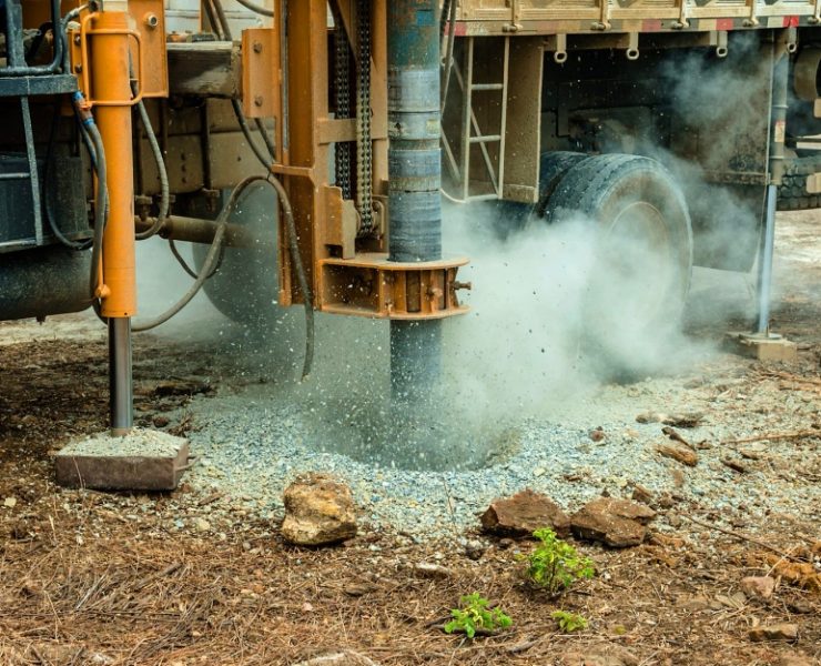
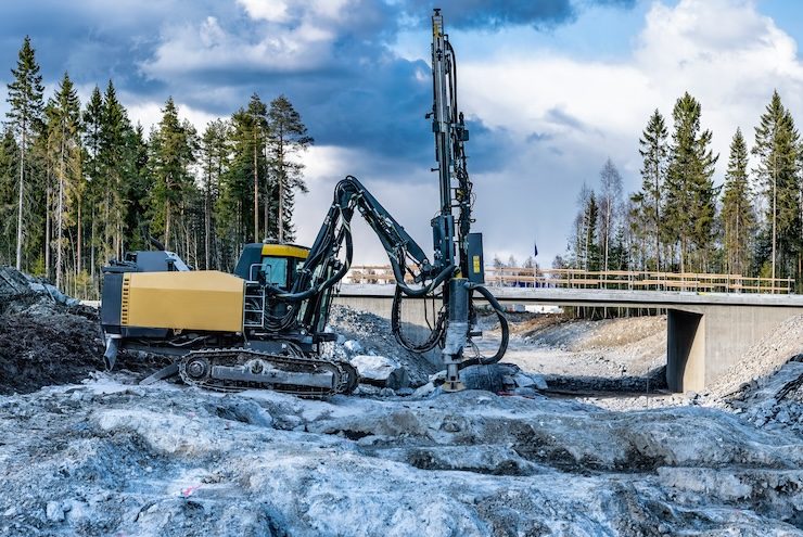
To conduct subsurface investigations, field investigation crews can utilize either the rotary drill or hollow stem auger method. Either choice will allow for the boring and recovery of undisturbed samples.
Diamond core drilling for site investigation can also be used. When core drilling is required, the core should be removed from the barrel, with care taken to not disturb the sample. If possible the core should be wrapped in plastic wrap to retain the moisture level in the core. It should then be placed in a core box, with the starting and ending depth written on wooden blocks located at the start and end of the core run. If there are any man-made breaks that occur during the drilling or placement process, these should be marked with a line. Cores are typically sampled in 5 foot intervals; if the length is less than 5 feet, more than one core run may fit into the box. In this situation, a block can be placed between the two cores, showing the ending depth of the first core and the starting depth of the second core. The name of the project, structure number, location, and depth information should be written on the side of the box.
Soil sampling is dictated by the type of soil being tested. Granular soils should be tested using split tube sampling, while plastic (cohesive) soils should be sampled used alternate split-tube and thin-wall sampling. Organic soil should be tested using thin-wall sampling. To start sampling, the tubes should be set at the in-place ground elevation or at the bottom of the water when the ground is submerged.
To assist with soil classification and testing, soil sampling devices that allow continuous soil samples of up to 5 feet long have been developed. Modern versions of these devices consists of smaller diameter tubes with hydraulic push systems. One common device is the Geoprobe system, which is capable of producing a 5 foot continuous soil sample of 1.5 inches in diameter. It is a stand-alone system that can retrieve samples in most soil conditions, with the option of using a percussive vibrating procedure for deeper penetration in dense or hard layers. Small diameter samples like the ones offered by the Geoprobe can only be used for soil classification and moisture testing.
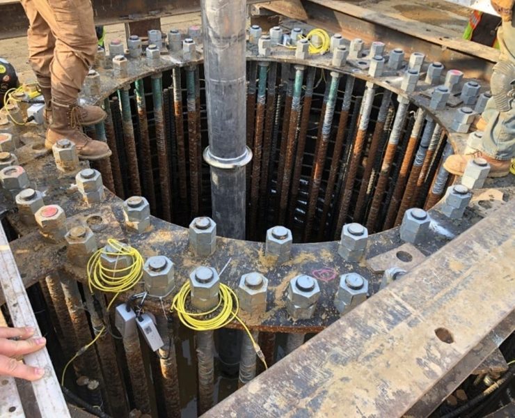
Borings should extend to depths that are sufficient to define the subsurface profile for structures, embankments, and geotechnical features. While the depths will vary based on the project, there are general guidelines that should be followed, such as boring to a minimum of 25 feet below proposed bottom of footing for a retaining wall. For bridges, the borings should be extended to a depth where a cumulative blow count of 2500 is achieved, excluding the blow counts from above the bottom elevation of footing and areas where the blow counts are less than 20 blows per foot. In soil, bridge borings should be carried to at least 60 feet below the proposed bridge foot elevation, unless bedrock is encountered.
Field logs for each boring should be prepared, with relevant information recorded for each boring. The required information may vary by construction job, but should include basics, such as the project identification and bridge number or job description, location of boring referenced to centerline survey, method of drilling and sampling employed, diameter of boring, date of start and completion of boring, and name of driller and crew.
All foundation borings and CPT soundings should be backfilled or sealed in accordance with local rules and regulations. After soil and rock samples are recovered from foundation borings, they should be stored and transported in an upright position with the origin vertical orientation. Samples should be stored in above freezing temperatures, with rock core wrapped in plastic wrap to retain its moisture level.
In Situ Measurements
In addition to information obtained from subsurface investigations, field crews can also glean information from investigations at or near the natural or existing surface. Geophysical investigations, in situ rock and soil measurements, investigation of rock slopes and outcrops and test pits can each provide information about the subsurface with little to no intrusion into the subsurface itself.
In situ rock measurements include measuring the orientation and frequency of discontinuities of rock outcrops or rock cores. The strike and dip of discontinuities within these rocks can impact the structural integrity of rock cuts. This is particularly true if these rocks are sloping towards the construction project. Field crews should draft a detailed description of the rock, including the type, changes in the formation, bedding thickness, weak zones, the strike and dip of discontinuities, join frequency, filling material and any groundwater that may be present. Crews should also take photographs, and utilize rock mass rating systems when possible.
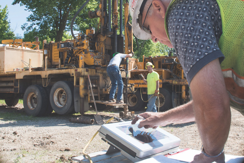
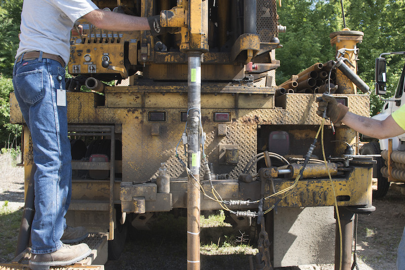
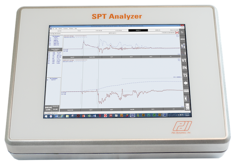
The Standard Penetration Test (SPT) is the most common method used by geotechnical engineers to quantitatively measure the relative density of soils. The data obtained by a SPT is used to estimate the strength and stiffness parameters for beating capacity and settlement analysis of foundations. SPT equipment includes a hammer system, drill rods and a sampling device, and is performed during hollow stem auger or rotary mud drilling operations. Once the drill or auger has reached the desired test elevation and the hole is clear of debris and cuttings, a sampler can be placed at the end of the appropriate length of drill rods. It is then driven by striking the end of the rod assembly with a hammer system. Once it has advanced either 18 inches or it can advance no further after 10 successive blows, the soil or rock is collected. It can then be analyzed for moisture content and identification of soil or rock type.
The Cone Penetration Test (CPT) is best used for accurately defining the subsurface stratigraphy. Data from this test is collected roughly every inch of penetration. This allows for a continuous picture of subsurface conditions. The CPT is both consistent and repeatable, and gives measurements such as resistivity and seismic measurements. However, it does not give high quality samples and it is limited in its ability to push past obstructions. This type of test involves an instrumented probe being pushed into the ground at a standard rate of 2 centimeters per second. While the probe is being advanced, internal sensors measure the soil’s resistance to penetration at the cone-shaped tip and along a six-inch sleeve. Other probes measure changes in pore water pressure. The CPT system includes the instrumented probe (penetrometer), the push system, and the data acquisition system. A 60 degree conical tip is attached to the free end of the penetrometer. The push dogs are 1 meter long with an outside diameter of 1.44 or 1.75 inches, with connections made of threaded joints.
The Flat plate Dilatometer Test, which is also known as the Dilatometer test (DMT), involves a rectangular flat plate that is pushed into the ground. In the middle, there is a thin circular steel diaphragm mounted on one side. After the dilatometer is pushed to the test depth, the diaphragm is inflated using gas pressure. Three pressure readings can then be taken: the pressure to start moving the membrane; the pressure required to move the center of the membrane 1.1 mm against the soil; and the pressure as the membrane deflates. These measurements are used the estimate the in situ lateral stress and lateral soil stiffness. The DMT blade is made of hardened steel, with the circular diaphragm made of stainless steel. The DMT tests are performed at 8 to 12 inch intervals, providing a near-continuous profile of the soil response. The DMT can be used in a range of soil types.
The Pressuremeter Test (PMT) is used to assess lateral earth pressure in-situ by lowering a cylindrical probe into a borehole. This probe is pressurized by inflating a flexible membrane. The way in which the borehole deforms in response to the pressure can be measured to provide information about lateral stress. The PMT is used to measure the in situ stress/strain behavior of site soils and rocks in situations where soil deformations are importation. The PMT consists of an up-hole gas pressure application system, connection tubing, cylindrical probe, support cabling, and readout device.
For areas that are inaccessible to drill rigs, test pits dug by backhoes may be used for shallow soil exploration. These test pits may also be used in pavement areas, instead of cores, to obtain a larger sample of the base and sublease aggregates. After testing, the pit should be backfilled with the cuttings or other suitable fill material, or the roadway should be properly patched.
Geophysical methods may also be used for in situ measurements. This involves the application of physics to the investigation of the earth in order to conduct subsurface investigations. These methods are particularly useful in highway design, construction, and during maintenance and repair of transportation systems. They include electrical methods, seismic methods, electromagnetic methods, and gravity methods. The advantage of using geophysical methods is that they can be utilized where drilling cannot be. However, drilling should generally be used in correlation with geophysical methods.
Electrical Resistivity Imaging (ERI) uses a property of subsurface materials known as resistivity, which is the ability of a material to impede the flow of electrical current. With an ERI test, a current is injected into the ground using two electrodes and measuring the potential difference using other electrodes also implanted into the ground. This method is highly useful, and can be performed in a wide range of terrains and soil types to detect subsurface cavities, to map bedrock or groundwater tables, or to delineate changes in subsurface soil stratigraphy. It can only be used when a contrast of the specific geophysical property exists between material types. ERI is labor intensive and can take a significant amount of time to set up; however, results are available for review immediately with the appropriate software.
Seismic methods, including refraction and multi-channel analysis of surface waves (MASW) are often used for transportation engineering applications. These tests measure how seismic waves travel through the subsurface to determine the physical properties of the soil and rock, which can then be used to map out the subsurface. These tests are useful in determining much of the subsurface information necessary for transportation projects, including bedrock topography, lithology, and depth to the water table. The methods include seismic refraction, seismic reflection and surface wave methods. All have similar techniques, which involve introducing a source of seismic disturbance into the ground, and then measuring the waves created by geophones placed in the ground at specific locations to measure the desired target. These methods can be used in many different types of terrain and soil conditions, and can determine depth to bedrock and lithology. Data process can be time-consuming and requires knowledge and expertise in geology.
Seismic refraction can be used to determine depth to bedrock and bedrock topography. A hammer strike gives a seismic signal, which is then recorded by geophones for a given amount of time. The hammer strike is repeated at various locations along the line as necessary for the investigation. MASW can be used to evaluate the stiffness of the subsurface. It can be conducted quickly, particularly with the use of land streamers and a repeatable source mounted on the back of a truck. After processing, an image of the shear wave velocity of the subsurface is produced; from this, properties of the subsurface materials can be inferred.
Ground Penetrating Radar (GPR) uses electromagnetic pulses in high frequencies transmitted from a radar antenna to image the subsurface. It is often used to create images near surface targets, such as the location of pipes and tanks, pavement characteristics, and the top of the water table. In soils with high percentages of clays and in the presence of water, the effectiveness of GPR decreases. However, GPR is quick and easy to run, and the data can be viewed in real-time.
Groundwater Investigations
In addition to the other methods of field investigations, groundwater investigations can be taken to assist in determining the parameters of a construction project. Prior to drilling, ground water levels at the investigation site should be estimated. These can be based on United States Geological Services topographic maps, from publications from state agencies, or from previous experience in the area. This will help to determine if groundwater will be a problem in a particular area or with a specific soil type. If these estimates show that groundwater may have an adverse impact on construction or the life of the project, a groundwater investigation should be conducted.
Groundwater can negatively impact a construction site in a number of ways, include slope stability and pavement performance. To ensure that a site is suitable for construction, a groundwater investigation can include geologic studies, SPT drilling and sampling, CPTs, installation of piezometers, lab testing, and permeability analysis. To more reliably measure the permeability of site soils, in situ testing may be used. However, this testing is generally more complicated and expensive than simply taking samples to a laboratory for testing.
With borings and soundings, field crews can record the soil moisture content, and if present, groundwater levels. In addition, any changes in the soil type should be noted, as they may indicate a confining layer within an aquifer. These tests represent a snapshot of the water levels; further study is necessary to properly assess water levels at the site.
A series of piezometers should be installed once water levels are high enough to interact with construction. At least three piezometers should be installed in the aquifer, which will allow the calculation of both flow direction and the elevation of the groundwater table. These piezometers should be monitored for at least a year to get a long-term picture of how the groundwater level fluctuates with seasons and climatic conditions.
In-situ field testing for aquifer characteristics should be performed to assist in the design of a drainage system. These may include slug tests and pump tests. A slug test involves introducing a known volume of water into a monitoring well, and measuring the rate at which the water level falls. The advantage of slug tests is that it is easy to perform and results are available quickly. However, these tests are relatively small, and so the results may only represent the characteristics of the aquifer closest to the well. Pump tests are performed by pumping a well for a period of time and taking note of how the hydraulic head changes in the aquifer over time. Pre-existing knowledge of the geologic setting is critical when performing pump tests in order to select the proper analytical procedure. In addition, laboratory testing on soils can be used to determine aquifer properties.
Finally, geophysical testing can be performed as another method of groundwater investigation. Methods such as Earth Resistivity Imaging (EMI) can be used to provide a seamless image of the subsurface, which includes the groundwater table.
A field investigation is an important tool to determine the engineering behavior of the earth materials on a construction site prior to commencing work on a project. Using a variety of techniques, including subsurface investigations, in situ measurements, and groundwater investigations, a field investigation crew can analyze the qualities of the soil, bedrock, strata, and groundwater. A successful geotechnical field investigation will help to ensure a favorable outcome for a construction project.
View the complete article here.
What are the common methods used for subsurface investigations in geotechnical field investigations?
Common methods for subsurface investigations include rotary drilling, hollow stem auger method, diamond core drilling, and various soil sampling techniques such as split tube sampling and thin-wall sampling.
How can geotechnical field investigations assess and manage groundwater-related challenges in construction projects?
Groundwater investigations involve estimating levels, installing piezometers, conducting slug and pump tests, and utilizing geophysical methods like Electrical Resistivity Imaging (ERI) to address groundwater-related challenges in construction projects.


