


Dynamic Formulae and Pile Driving
Attempts to determine pile capacity using dynamic analysis date back to the 19th century, when a dynamic formula that considered the energy of the pile driving hammer and the set of the pile was developed to find bearing capacity. In the early 1940s, the results of a large study on dynamic formulas were published and discussed by very prominent engineers including Karl Terzhagi. Those scholars concluded that none of the formulas were accurate (see Likins, G. E., Fellenius, B. H., Holtz, R. D., March, 2012. Pile Driving Formulas: Past and Present – Full-Scale Testing and Foundation Design; ASCE Geo-Institute Geotechnical Special Publication No. 227; 737-753.) and recommended instead the use of static loading tests to determine pile capacity. Today dynamic formulas have largely been replaced by more accurate wave equation analyses and high strain dynamic testing.
 Wave Equation Analysis
The analysis begins with the hammer ram falling and attaining an initial velocity at impact. This method is the best technique for predicting the relationship of pile capacity and blow counts (or set per blow), and the only method available to predict driving stresses. Download the freeware PDI-Wave to visualize wave propagation after ram impact, as well as resulting forces, velocities, stresses and displacements.
Improvements to Smith’s method include work by GRL to incorporate a thermodynamic diesel hammer model and residual stresses. The GRLWEAP Wave Equation Analysis of Piles program is based on Smith’s method. The wave equation approach is an excellent predictive tool for analysis of impact pile driving, but it has some limitations. These are mainly due to uncertainties in quantifying some of the required inputs, such as actual hammer performance and soil parameters.
High Strain Dynamic Testing
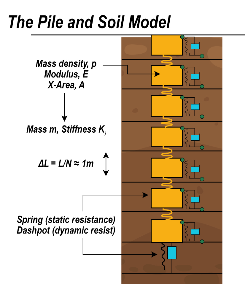
When a hammer or drop weight strikes the top of a foundation, a compressive stress wave travels down its shaft at a speed c, which is a function of the elastic modulus E and mass density. The impact induces a force F and a particle velocity v at the top of the foundation. The force is computed by multiplying the measured signals from a pair of strain transducers attached near the top of the pile by the pile area and modulus. The velocity measurement is obtained by integrating signals from a pair of accelerometers also attached near the top of the pile. Strain transducers and accelerometers transmit data to a high strain dynamic testing system such as the Pile Driving Analyzer® (PDA), for signal processing and results.
As long as the wave travels in one direction, force and velocity are proportional: F = Zv, where:
- Z = EA/c is the pile impedance
- E is the pile material modulus of elasticity
- A is the cross-sectional area of the pile
- c is the material wave speed at which the wave front travels
Soil resistance forces along the shaft and at the toe cause wave reflections that travel and are felt at the top of the foundation. The times at which these reflections arrive at the pile top are related to their location along the shaft. The measured force and velocity near the pile top thus provide necessary and sufficient information to estimate soil resistance and its distribution.
The resulting estimated total soil resistance includes both static and viscous components. The static resistance is obtained by subtracting the dynamic component from the total soil resistance. The dynamic component is computed as the product of the pile velocity times a soil parameter called the Damping Factor. The damping factor is related to soil grain size.
The energy delivered to the pile is directly computed as the work done on the pile from the integral of force times incremental displacement ( ∫Fdu ) which is easily evaluated as force times velocity integrated over time ( ∫Fvdt ). Maximum compression stresses at the pile top come directly from the measurements. The measurements also allow direct computation of the compression stress at the pile toe and the tension stresses along the shaft. Pile integrity can be evaluated by inspecting the measurements for early tension returns (caused by pile damage) prior to the reflection from the pile toe; lack of such reflections indicates a pile with no defects.
High Strain Dynamic Testing encompasses Dynamic Pile Monitoring and Dynamic Load Testing. Both are covered by ASTM D4945. Pile Driving Monitoring consists of performing real-time evaluation of Case Method capacity, energy transfer, driving stresses and pile integrity for every blow. Dynamic Load Testing involves combining field measurements obtained with a high strain dynamic testing system such as the PDA with wave-equation based analytical procedures performed with a signal matching program such as CAPWAP®. Dynamic Load Testing predicts soil behavior including static load capacity, soil resistance distribution, pile soil load transfer characteristics, soil damping and quake values, and pile load versus movement plots (e.g. a simulated static load test).
Low Strain Integrity Testing
Wave propagation theory can also be applied to situations where a light impact is applied to a pile, resulting in a low strain. A compression wave will still travel down the pile when it is impacted by a small hand held hammer. Much like in High Strain Testing, this wave will travel at a constant speed c. Changes in pile impedance Z produce wave reflections.
The application of the wave equation theory to waves caused by small impacts is the basis for Low Strain Dynamic Integrity Testing. This procedure is performed with a Pile Integrity Tester (PIT), a hand-held hammer to generate an impact, and an accelerometer placed on top of the pile to be tested to measure the response to the hammer impact. Given a known stress wave speed, records of velocity (integrated from the accelerometer signals) at the pile head can be interpreted to reveal pile non-uniformities (changes in impedance). Interpretation is usually done in the time domain (Pulse echo, or Sonic echo) but data can also be evaluated by measuring the hammer force and analyzing in the frequency domain (Transient Dynamic Response). Pile length may also be evaluated. This non-destructive testing method is usually applied to concrete piles, concrete filled pipe piles, drilled shafts, auger cast-in-place (continuous flight auger) piles, and sometimes timber piles. Usually, the method is applied to piles not connected to a structure, but good results are often obtained for piles embedded in structures (such as cell-phone towers, transmission towers, and bridges). This method is covered under ASTM D5882.
What are dynamic formulae in pile driving?
Dynamic formulae in pile driving are mathematical equations used to estimate the bearing capacity of driven piles. They take into account the energy transfer from the pile hammer to the pile, the pile's penetration resistance, and other factors such as hammer efficiency, cushioning, and soil resistance. Some popular dynamic formulae include the Engineering News Record (ENR) formula, Hiley formula, and Janbu formula.
What is the importance of dynamic formulae in pile driving?
Dynamic formulae play a crucial role in pile driving by providing engineers with a practical method to estimate pile bearing capacity during the design phase and in the field. Accurate capacity estimation helps ensure the stability and safety of the foundation, prevents overdesign, and can lead to cost and time savings in construction projects.