


Coping with Stress
By Ryan C. Allin, P.E., Vice President, Pile Dynamics, Inc.
When monitoring pile stresses during dynamic testing it is important to note what stresses the PDA measures and what stresses are estimated. Further, the values being estimated require the user’s understanding of how those values are calculated and the underlying assumptions/ limitations of those calculations.
Strain measurements taken near the pile top (when multiplied by the material modulus) allow for direct measurement of the compression stress occurring at the pile top. While it is necessary and useful to monitor top compressive stresses, they are not always critical. In fact, in cases where the pile encounters bedrock the maximum compression stress may occur at the pile toe and may be significantly higher than at the pile top.
By measuring both strain and velocity near the pile top, the stress wave can be separated into downward traveling and upward traveling wave components. Based on these values, the maximum stresses at the pile toe can also be calculated. For these calculations to provide a reasonably accurate stress the PDA theory assumes that:
- The pile is uniform in cross-section and material.
- Critical compression stress maxima occur either at the pile top or bottom.
- Shaft resistance is relatively insignificant compared to end bearing (otherwise the toe compression stresses would be lower than those at the top.)
- The pile is one-dimensional, i.e., bending cannot be calculated below the sensor level.
Noting the last limitation is important, because stress wave analysis uses one-dimensional stress wave propagation theory which means that the estimated maximum compressive stress values average over the cross section.
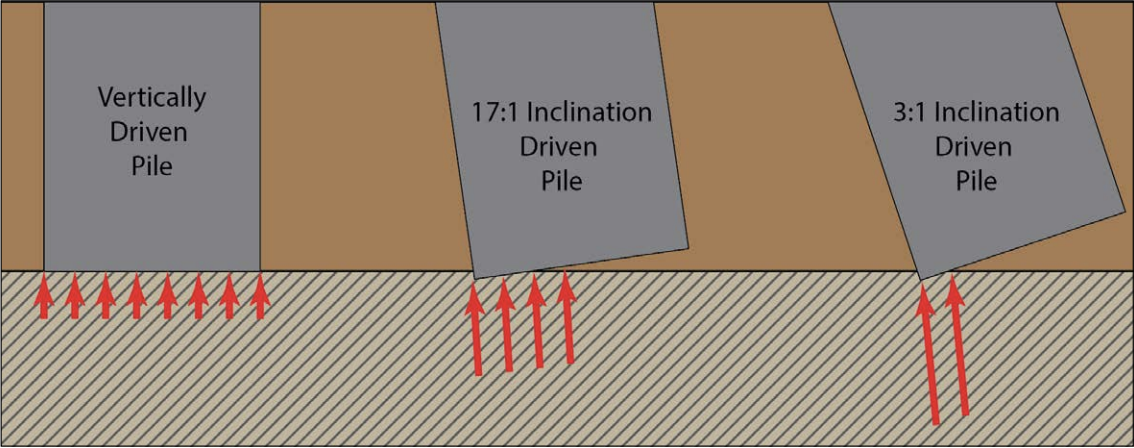
This presents a problem in dealing with any type of pile and may be most extreme for large diameter open ended pipe piles (LDOEP). The likelihood of LDOEPs encountering bedrock uniformly over the full cross-section of the pile is low (Figure 1).
This issue was recently discussed in a paper presented at GeoCongress 2022. The paper outlines two sites where LDOEP piles were required to be driven through rock layers to achieve the desired pile design requirements.
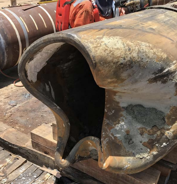
At each site one LDOEP pile sustained damage during driving through a rock layer due to eccentric stresses at the pile toe. The pile toe would be expected to contact the rock on one side of the pile, while the opposite side remains in the softer upper soils. Two modes of failures can be envisioned. The non-uniform rock surface would require that the bottom force, estimated by the PDA from the pile top measurements, would only be supported by a fraction of the steel area and lead to local buckling. In a second scenario, the bottom force would be causing bending over the whole cross-section, some distance above the pile toe. To model this condition and estimate the eccentric stresses, numerous driveability analyses were performed. For these studies, it was assumed that the soil resistance at the pile toe would have an eccentricity equal to approximately one-half the inner radius of the LDOEP which would lead to an estimate of additional bending stresses due to overall bending. For an LDOEP encountering a rock at an inclined angle, a similar bending stress estimate may be possible as schematically demonstrated in Figure 1. The presumed eccentricity of one-half of the pile’s inner radius would be a reasonable and somewhat conservative compromise.
Case 1
42 in (1070mm) O.D. pipe piles were driven into a shallow hard gypsum rock layer on a 1:17 inclination suggesting the piles would experience eccentric forces once bedrock was encountered. All four foundation piles encountered refusal conditions at approximately 16 ft (5m) penetration and pile damage was observed on the first of the four piles driven.
CAPWAP® analysis indicated uniform average stresses near the bottom of the piles were below the yield strength of steel at the pile toe. Modeling an eccentric stress with a moment equal to one-fifth of the pile’s inner radius resulted in combined toe stresses where only the initial pile that experienced pile toe damage (Figure 2) would have been subjected to stresses above the yield strength. The other three piles had combined stresses near or below the yield strength of the steel.
Case 2
42 in (1070mm) O.D. pipe piles were driven into a sand overlaying limestone and calcarenite on a 1:17 inclination. Two of the four piles encountered refusal driving in the limestone at approximately 92 ft (28m) pile toe depth. Dynamic testing indicated one of the piles had a significant impedance reduction 13 ft (4m) above the pile toe, where the thicker-walled “driving shoe” transitions to the nominal wall thickness of the pile. This damage was later confirmed through coring. Again, CAPWAP® results indicated uniform average stress values below the yield strength of the steel. In this instance assuming an eccentricity of one-quarter of the pile inner radius, the combined eccentric stresses exceeded the yield strength for the pile that sustained damage and was below the yield strength for the pile that encountered refusal without pile damage.
Conclusions
The possibility of eccentric stresses for LDOEP piles should be considered when encountering abrupt refusal driving conditions. Based on these two examples the assumption of an eccentricity equal to one-third or one-quarter of the piles inner radius would be reasonable for these piles driven at a relatively small inclination angle (1:17). Piles with greater inclinations as well as piles encountering sloped bedrock likely should consider higher eccentricities for calculation of the additional stress. The application of these eccentricities can be useful for pre-construction driveability as well as dynamic monitoring during installation.
What are eccentric stresses in Large Diameter Open Ended Pipe piles (LDOEP)?
Eccentric stresses in LDOEPs occur when these piles encounter bedrock unevenly across their cross-section. This leads to one side of the pile toe contacting the hard rock while the other side remains in softer upper soils. These stresses can cause local buckling or bending across the pile cross-section, potentially leading to pile damage.
How can the potential for damage from eccentric stresses in LDOEP piles be estimated?
The potential for pile damage can be estimated by modeling the eccentric stresses and performing numerous driveability analyses. For example, assuming an eccentricity equal to one-third or one-quarter of the pile's inner radius was found to be reasonable for piles driven at a small inclination angle. For piles with greater inclinations or encountering sloped bedrock, higher eccentricities should be considered. This can help in pre-construction driveability assessments and dynamic monitoring during installation.
What are some real-world examples of LDOEP pile damage due to eccentric stresses?
The article presents two real-world examples where LDOEP piles were required to be driven through rock layers. In both cases, one pile sustained damage due to eccentric stresses at the pile toe. The first case involved 42-inch O.D. pipe piles encountering a shallow hard gypsum rock layer, while the second case involved similar sized piles driven into sand overlaying limestone and calcarenite. In both cases, modeling of the eccentric stresses helped identify why certain piles sustained damage while others did not.