Chapter 8 – Rebar Cages
- Chapter 1 – Selection and Use of Drilled Shaft Foundations for Transportation Structures
- Chapter 2 – Site Characterization
- Chapter 4 – General Construction Methods
- Chapter 5 – Tools and Equipment
- Chapter 6 – Casings and Liners
- Chapter 8 – Rebar Cages
- Chapter 9 – Placement and Design of Concrete For Drilled Shafts
From Drilled Shafts: Construction Procedures and LRFD Design Methods by FHWA
8.1 INTRODUCTION
The design of the reinforcing, or “rebar,” cage for a drilled shaft is a necessary step in the engineering process. Rebar cages will be considered from two perspectives in this manual: (1) geometry of the steel necessary to resist stresses that develop because of loads applied to the drilled shaft, which is addressed in Chapter 16, and (2) the characteristics of the cage from the perspective of constructability, which is addressed in this chapter.
A rebar cage for a drilled shaft is made up of longitudinal bars that are normally distributed with equal spacing around the outside of a cylinder. Transverse reinforcing is placed around and attached to the longitudinal bars, with the longitudinal and transverse steel being held together with ties, clamps, or, in special cases, with welds. Other components of a rebar cage that may be used are hoops for sizing, guides for centering the cage in the borehole and the tremie inside the cage, and stiffeners and pickup devices to aid in lifting the cage. For long cages and cages with large diameters, temporary or permanent strengthening elements should be provided to prevent permanent distortion of the cage as a result of stresses due to lifting and placing.
The required amount of reinforcing steel to be placed in a drilled shaft must satisfy structural requirements. The axial load, lateral load, and moment (taking into account the eccentricities due to accidental batter and tolerance in location) can be applied to the shaft head, and the combined stresses can be computed. The placement of reinforcing steel is made in consideration of the stresses that will exist, using appropriate load factors in the computations. However, when considering how the steel cage resulting from the structural computations is to be assembled and handled during construction, a number of important empirical rules discussed in this chapter should be followed.
The assumption is made that the rebar cage is always placed in the excavation, and the concrete is then placed, during which it flows around the cage. Short rebar cages may be pushed or vibrated into fresh concrete, but such a procedure is unusual.
8.2 PROPERTIES OF STEEL
The 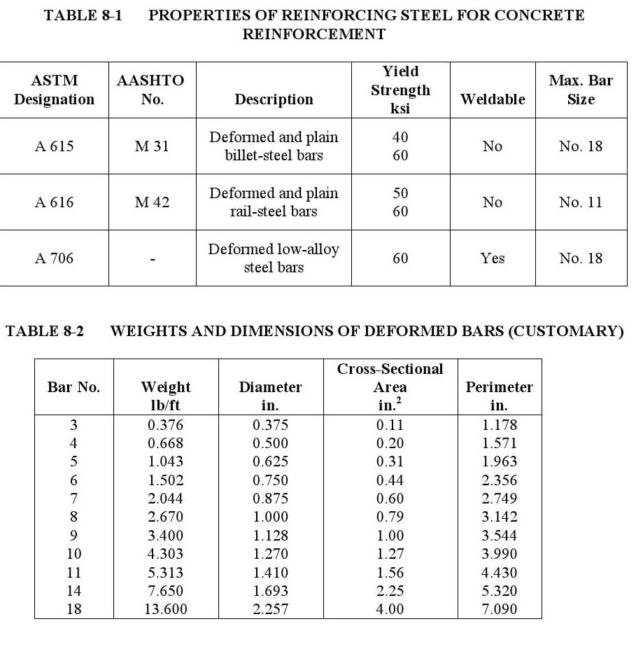 American Society for Testing and Materials (ASTM) provides specifications for several steels that can be used for reinforcing drilled shafts. These specifications are presented in the Annual Book of ASTM Standards and are conveniently collected in Publication SP-71 of the American Concrete Institute (ACI, 1996). Most of the ASTM steels also have a designation from the American Association of State Highway and Transpo
rtation Officials (AASHTO). The properties of steel that may be employed for building rebar cages for drilled shafts are shown in Table 8-1. The steel that is usually available is AASHTO M 31 (ASTM A 615) in either Grade 40 [40 ksi yield strength] or Grade 60 [60 ksi yield strength]. The specifications in the table do not address the welding of the M 31 or M 42 steels because these bars are not to be welded in normal practice. Where the welding of the rebar cage is desirable, a weldable steel, ASTM A 706, can be specified, but availability is often limited.
Galvanized or epoxy-coated steel is also available for longitudinal and transverse reinforcement for those cases where there is increased risk of corrosion. Epoxy-coated steel is sometimes specified for drilled shaft rebar cages in marine environments, where the chlorides content of the ground and/or surface water is high. Nicks and blemishes in the coating that may occur during lifting and placement of drilled shaft reinforcement into the excavation can become points for accelerated corrosion; accordingly, specification of coated bars can present unusual challenges for construction of drilled shafts. Alternatively, the rebar may be used without epoxy, and a dense concrete of low permeability may be specified, as discussed in Chapter 9. Increased concrete cover requirements can also be used to increase corrosion protection.
The designations of deformed bars, their weights per unit length, cross-sectional areas, and perimeters are given in Table 8-2. The values shown in the table are equivalent to those of a plain bar with the same weight per unit length as the deformed bar. Table 8-1 shows the maximum size of bar that is available for the designations of steel. Plain bars are not recommended.
The modulus of elasticity of steel is usually taken as 29,000,000 psi. For design purposes the stress-strain curve for steel is usually assumed to be elastic-plastic, with the knee at the yield strength (Ferguson, 1981).
On rare occasions, it may be advantageous to use high strength reinforcement, such as Grade 75. Figure 8-1 is a photo of the GR75 threaded bars that were used in the fast-track reconstruction of the collapsed I- 35W bridge in Minneapolis. Threaded couplers were used to make splice connections. Even higher strength bars are available, but the current AASHTO design code does not include provisions for reinforcement with yield strengths higher than 75 ksi.
8.3 LONGITUDINAL REINFORCING
The principal role of the longitudinal reinforcing steel in drilled shafts for transportation structures is to resist stresses due to bending and tension. If the computed bending and tensile stresses are negligible, there may seem to be no need at all for longitudinal steel except as required by specifications. However, construction tolerances will allow nominally concentric axial loads to be applied with some amount of eccentricity, unanticipated lateral loads may occur (such as those caused by long-term lateral translation of soil), and the top portion of any drilled shaft will need to act as a short column if there is any axial load. Therefore, it is good practice to provide at least some amount of longitudinal steel reinforcing in all drilled shafts for bridge foundations. AASHTO (2007) design specifications require that reinforcing for drilled shafts extend a minimum of 10 ft below the plane where the soil provides “fixity”, although fixity is not clearly defined and some judgment on this issue is left to the designer.
In virtually all designs, the reinforcement requirements will be greatest within the upper few diameters below the groundline and will diminish rapidly with depth. Therefore, the maximum number of longitudinal bars will be required in the upper section of a drilled shaft. Some of the bars can be eliminated, or “cut off,” as depth increases. With some methods of construction, it is desirable that the cage should be able to stand on the bottom of the shaft excavation during the placement of the concrete (e.g. when extracting temporary casing), and thus at least some of the longitudinal bars must extend over the full length of the shaft.
In order for the reinforced concrete to function as designed, the longitudinal bars must bond to the concrete, and therefore the surface of the bars must be free of excessive rust, soil, oils, or other contaminants. Deformed bars are used to ensure that adequate bond to the concrete is achieved. As the concrete rises to displace the slurry around the rebar steel, there is a possibility that some of the water, bentonite, or polymer will be trapped around the deformations. As discussed in Chapter 7, there is no evidence at present to indicate that significant loss of bond may occur in wet construction if the slurry meets appropriate specifications at the time the concrete is placed.
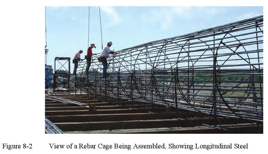
It is conceptually possible to vary the spacing of the longitudinal bars and to orient the cage in a specific direction in the case where the main forces causing bending have a preferential direction. However, any small potential material savings that would be gained by such a procedure are generally more than offset by the risk of delays in the inspection and construction, or risks of misalignment or twisting of the cage. Therefore, the longitudinal bars are recommended to be spaced equally around the cage unless there are compelling reasons for nonsymmetrical spacing. If the number of bars in a symmetrical cage are at least six, then the bending resistance is almost equal in any direction. A view of the longitudinal steel in a rebar cage that is being assembled on a job site is shown in Figure 8-2.
The minimum clear spacing between longitudinal bars (and between transverse bars or spiral loops, as well) must be sufficient to allow free passage of the concrete through the cage and into the space between the cage and the borehole wall. This spacing is particularly important because drilled shaft concrete is placed without resorting to vibrating the concrete. Although this spacing is somewhat dependent upon other characteristics of the fluid concrete mix, the size of the largest coarse aggregate in the mix is an important characteristic. Recent research reported by Dees and Mullins (2005) suggest that a minimum spacing of 8 times the size of the largest coarse aggregate in the mix is needed to avoid blocking for tremie-placed concrete. Where tremie placement of concrete is anticipated, many agencies require a minimum opening between bars which is 5 inches in both the vertical and horizontal direction, and at least 10 times the size of the largest coarse aggregate in the mix. If concrete placement into a dry shaft is assured, then a smaller spacing on the order of 5 times the size of the largest coarse aggregate may be considered. The bar size that is selected for the longitudinal steel must be such that the proper clear spacing between bars is maintained. The recommendations for minimum clear spacing should also apply to access tubes which may be included for non-destructive testing as described in Chapter 20.
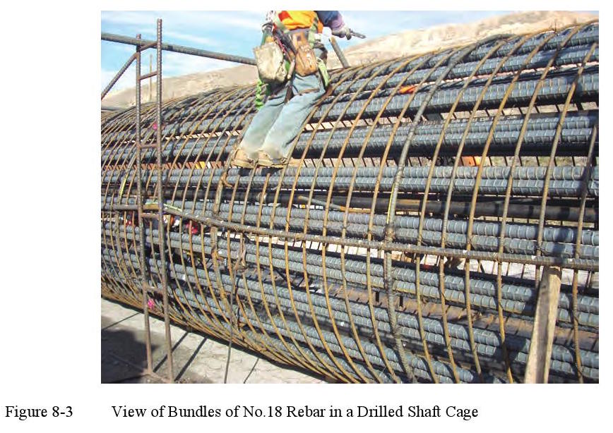
In some instances, two or three bars can be clustered, or “bundled,” together to increase the steel percentage while maintaining a cage with appropriate rebar spacing. Bundling of bars may require a greater development length beyond the zone of maximum moment. A photograph of a cage with bundles of two No. 18 bars is shown in Figure 8-3.
 Two concentric rebar cages have occasionally been used to provide an increased amount of steel for drilled shafts with unusually large bending moments. However, the two cages result in increased resistance to lateral concrete flow, and greatly increase the risk of defective concrete at the perimeter of the drilled shaft and in the space between the two cages. In such cases, consideration should be given to using high strength bars, bundled bars and/or increased diameter for the drilled shaft
8.4 TRANSVERSE REINFORCING
The transverse reinforcing steel has the function of: 1) resisting the shearing forces that act on a drilled shaft, 2) holding the longitudinal steel in place during construction, 3) providing the drilled shaft with sufficient resistance against compressive or flexural stresses, and 4) confining the concrete in the core of the cage to give the drilled shaft post-yield ductility. The transverse reinforcing steel is provided in the form of ties, hoops or spirals.
When either a transverse tie or spiral is used, it is essential that the end of the steel be anchored in the concrete for a distance sufficient to assure that the full bar capacity is achieved at the point of connection of the two ends of the tie or the end of one spiral section and the beginning of the next. Figure 8-4 shows two scenarios for providing such anchorage. On the left is a schematic of a series of transverse ties. It shows the anchorage of the transverse ties being developed by the use of hooks. The hooks shown in the figure will complicate the assembly of the steel, and the protrusion of the bars into the interior of the cage could interfere with the introduction of a tremie or the placing of the concrete by free fall. The best practice is to anchor the transverse steel by the use of a sufficient amount of lapping. The use of sections of spiral anchored with a lap is illustrated on the right side of Figure 8-4. An extension of the steel beyond the point where its resistance is needed (“development length”), computed according to the relevant concrete design code, is recommended for the steel on each side of the connection point for all lap joints. ACI (1995) recommends in general a development length in inches of 0.04Abfy/[(f ’c)0.5] for bars of No. 11 size or smaller that take tension, such as transverse steel, where Ab is the cross sectional area of the bar in square inches, fy is the yield strength of the steel in psi, and f ’c is the cylinder compression strength of the concrete, also in psi. Some agencies specify that spiral steel be lapped for one full turn.
Craftspeople assembling the reinforcing steel should be skilled in tying rebar so that the bars will maintain their relative positions as the concrete is poured. The cage should be assembled to resist the forces caused by the concrete as it flows from the inside of the cage. An undesirable displacement of the transverse steel is sketched in Figure 8-5. A frequent cause of that kind of deformation is that the steel in the transverse ties is too small. On some cages, No. 3 or No. 4 bars may satisfy structural requirements, but larger bars may be needed to prevent permanent distortion of the cage during handling and placement of concrete. The stability of rebar cages for drilled shafts during handling and concrete placement can be improved by completely tying every crossing between the longitudinal and transverse steel, rather than tying only some of the crossings, as is common practice in some localities.
It is possible, of course, to assemble the reinforcing steel by welding if the proper steel is at hand. But as noted earlier, weldable steel is not normally used for rebar cages in the United States (in Europe, it is more commonly available).
Note also that distortion of the cage can occur as hydraulic forces pull the top of the cage downward and laterally if concrete flows to one side of the excavation to fill a void or oversized excavation. These cavities can be hidden by casing and then cause distortion of the cage during removal of temporary casing. Where the potential for these conditions exists (for example, in karstic limestone or rock where large overbreak is possible), then it is especially important that the cage be carefully tied and supported during concrete placement and removal of casing. The cage and concrete mix properties should also be designed to ensure that good passing ability is present. Stiffeners (described subsequently) may be designed to remain in the cage during concrete placement.
Considerations for ductility in high moment regions near the top of the shaft, particularly in seismic regions, may indicate that relatively large amount of transverse reinforcement may be required. Tight spacing on spiral reinforcement (less than 5 inch pitch) can result in constructability problems with concrete flow through the cage. The photos in Figure 8-6 illustrate problems resulting from tightly spaced spiral reinforcement and a concrete mix with insufficient passing ability for this congested condition. The failure of the concrete to flow through the cage resulted in inadequate cover and poor contact between the soil and shaft.
-
 SPW911 Sheet Pile Design Software
Rated 5.00 out of 5$150.00 – $599.99Price range: $150.00 through $599.99
 -
 Sheet Pile Design (PDF Download)
Rated 5.00 out of 5$89.00
 -
 Pile Driving (PDF Download)
$89.00
-
 Marine Construction Volumes 1 & 2 (PDF Download)
$157.00
-
 Pile Driving (Book)
$89.00


