Chapter 3 – Dredging Equipment and Techniques
For a complete version of this document click here.
3-1. Purpose
This chapter includes a description of the dredging equipment and techniques used in dredging activities in the United States and presents advantages and limitations for each type of dredge. Guidance is provided for selection of the best dredging equipment and techniques for a proposed dredging project to aid in planning and design.
3-2. Factors Determining Equipment Selection
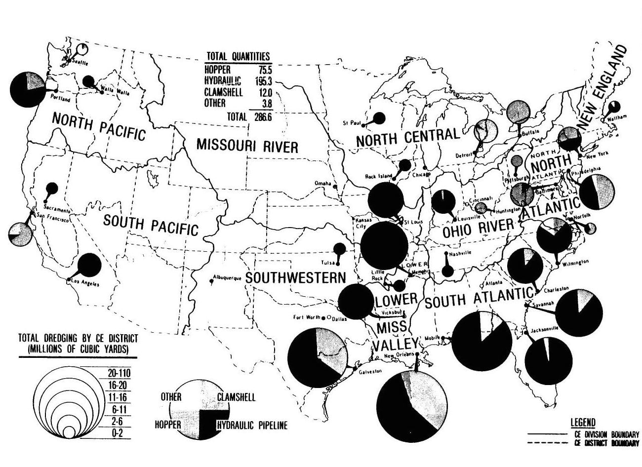
a. The types of equipment used, by both the Corps and private industry, and the average annual amount of dredging associated with each type are shown in Figure 3-1. The dredging methods employed by the Corps vary considerably throughout the United States. Principal types of dredges include hydraulic pipeline types (cutterhead, dustpan, plain suction, and side caster), hopper dredges, and clamshell dredge. The category of “other” dredges in Figure 3-1 includes dipper, ladder, and special purpose dredges. However, there are basically only three mechanisms by which dredging is actually accomplished:
(1) Suction dredging. Removal of loose materials by dustpans, hoppers, hydraulic pipeline plain suction, and sidecasters, usually for maintenance dredging projects.
(2) Mechanical dredging. Removal of loose or hard, compacted materials by clamshell, dipper, or ladder dredges, either for maintenance or new work projects.
(3) A combination of suction and mechanical dredging. Removal of loose or hard, compacted materials by cutterheads, either for maintenance or new work projects.
b. Selection of dredging equipment and method used to perform the dredging will depend on the following factors:
(1) Physical characteristics of material to be dredged.
(2) Quantities of material to be dredged.
(3) Dredging depth.
(4) Distance to disposal area.
(5) Physical environment of and between the dredging and disposal areas.
(6) Contamination level of sediments.
(7) Method of disposal.
(8) Production required.
(9) Type of dredges available.
3-3. Hopper Dredges
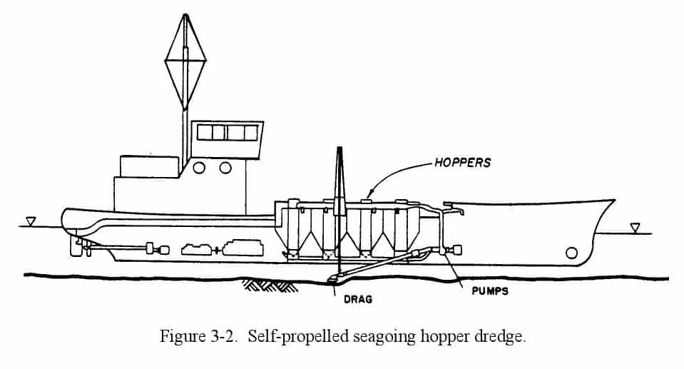
a. General. Hopper dredges are self-propelled seagoing ships of from 180 to 550 ft in length, with the molded hulls and lines of ocean vessels (fig. 3-2). They are equipped with propulsion machinery, sediment containers (hoppers), dredge pumps, and other special equipment required to perform their essential function of removing material from a channel bottom or ocean bed. Hopper dredges have propulsion power adequate for required free-running speed and dredging against strong currents and excellent maneuverability for safe and effective work in rough, open seas. Dredged material is raised by dredge pumps through dragarms connected to drags in contact with the channel bottom and discharged into hoppers built in the vessel. Hopper dredges are classified according to hopper capacity: large-class dredges have hopper capacities of 6000 cu yd or greater, medium-class hopper dredges have hopper capacities of 2000 to 6000 cu yd, and small-class hopper dredges have hopper capacities of from less than 2000 to 500 cu yd. During dredging operations, hopper dredges travel at a ground speed of from 2 to 3 mph and can dredge in depths from about 10 to over 80 ft. They are equipped with twin propellers and twin rudders to provide the required maneuverability. Table 3-1 gives available specifications for all vessels in the Corps hopper dredge fleet.
b. Description of Operation.
(1) General. Operation of a seagoing hopper dredge involves greater effort than that required for an ordinary ocean cargo vessel, because not only the needs of navigation of a selfpropelled vessel but also the needs associated with its dredging purposes must be satisfied. Dredging is accomplished by progressive traverses over the area to be dredged. Hopper dredges are equipped with large centrifugal pumps similar to those employed by other hydraulic dredges. Suction pipes (dragarms) are hinged on each side of the vessel with the intake (drag) extending downward toward the stern of the vessel. The drag is moved along the channel bottom as the vessel moves forward at speeds up to 3 mph. The dredged material is sucked up the pipe and deposited and stored in the hoppers of the vessel. Once fully loaded, hopper dredges move to the disposal site to unload before resuming dredging. Unloading is accomplished either by opening doors in the bottoms of the hoppers and allowing the dredged material to sink to the open-water disposal site or by pumping the dredged material to upland disposal sites. Because of the limitations on open-water disposal, most hopper dredges have direct pumpout capability for disposal in upland confined sites. Before there were environmental restrictions, hopper dredges were operated with the primary objective of obtaining the maximum economic load; i.e., removing the maximum quantity of material from the channel prism in the shortest pumping time during a day’s operation.
(2) Hopper dredging is accomplished by three methods: (a) pumping past overflow, (b) agitation dredging, and (c) pumping to overflow. The use of these methods is controlled to varying degrees by environmental legislation and the water quality certification permits required by the various states in which dredging is being accomplished. The environmental effects of these methods must be assessed on a project-byproject basis. If the material being dredged is clean sand, the percentage of solids in the overflow will be small and economic loading may be achieved by pumping past overflow. When contaminated sediments are to be dredged and adverse environmental effects have been identified, pumping past overflow is not recommended. In such cases, other types of dredges may be more suitable for removing the contaminated sediments from the channel prism. If hopper dredges are not allowed to pump past overflow in sediments that have good settling properties, the cost of dredging increases. The settling properties of silt and clay sediments may be such that only a minimal load increase would be achieved by pumping past overflow. Economic loading, i.e. the pumping time required for maximum production of the hopper dredge, should be determined for each project. These determinations, along with environmental considerations, should be used to establish the operation procedures for the hopper dredge.
(3) Agitation dredging. Agitation dredging is a process which intentionally discharges overboard large quantities of fine-grained dredged material by pumping past overflow, under the assumption that a major portion of the sediments passing through the weir overflow will be transported and permanently deposited outside the channel prism by tidal, river, or littoral currents. Agitation dredging should be used only when the sediments dredged have poor settling properties, when there are currents in the surrounding water to carry the sediments from the channel prism, and when the risk to environmental resources is low. Favorable conditions may exist at a particular project only at certain times of the day, such as at ebb tides, or only at such periods when the streamflow is high. To use agitation dredging effectively requires extensive studies of the project conditions and definitive environmental assessments of the effects. Agitation dredging should not be performed while operating in slack water or when prevailing currents permit redeposit of substantial quantities of the dredged material in the project area or in any other area where future excavation may be required. Refer to para 3-12 for more information on this topic.
(4) Refer to ER 1125-2-312 for instructions for hopper dredge operations.
c. Application. Hopper dredges are used mainly for maintenance dredging in exposed harbors and shipping channels where traffic and operating conditions rule out the use of stationary dredges. The materials excavated by hopper dredges cover a wide range of types, but the hopper dredge is most effective in the removal of material which forms shoals after the initial dredging is completed. While specifically designed drags are available for use in raking and breaking up hard materials, hopper dredges are most efficient in excavating loose, unconsolidated materials. At times, hopper dredges must operate under hazardous conditions caused by fog, rough seas, and heavy traffic encountered in congested harbors.
d. Advantages. Because of the hopper dredge’s design and method of operation, the self-propelled seagoing hopper dredge has the following advantages over other types of dredges for many types of projects:
(1) It is the only type of dredge that can work effectively, safely, and economically in rough, open water.
(2) It can move quickly and economically to the dredging project under its own power.
(3) Its operation does not interfere with or obstruct traffic.
(4) Its method of operation produces usable channel improvement almost as soon as work begins. A hopper dredge usually traverses the entire length of the problem shoal, excavating a shallow cut during each passage and increasing channel depth as work progresses.
(5) The hopper dredge may be the most economical type of dredge to use where disposal areas are not available within economic pumping distances of the hydraulic pipeline dredge.
e. Limitations. The hopper dredge is a seagoing self-propelled vessel designed for specific dredging projects. The following limitations are associated with this dredge:
(1) Its deep draft precludes use in shallow waters, including barge channels.
(2) It cannot dredge continuously. The normal operation involves loading, transporting material to the dump site, unloading, and returning to the dredging site.
(3) The hopper dredge excavates with less precision than other types of dredges.
(4) Its economic load is reduced when dredging contaminated sediments since pumping past overflow is generally prohibited under these conditions and low-density material must be transported to and pumped into upland disposal areas.
(5) It has difficulty dredging side banks of hardpacked sand.
(6) The hopper dredge cannot dredge effectively around piers and other structures.
(7) Consolidated clay material cannot be economically dredged with the hopper dredge.
3-4. Cutterhead Dredges
a. General. The hydraulic pipeline cutterhead suction dredge is the most commonly used dredging vessel and is generally the most efficient and versatile (fig. 3-3). It performs the major portion of the dredging
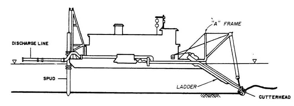
workload in the United States. Because it is equipped with a rotating cutter apparatus surrounding the intake end of the suction pipe, it can efficiently dig and pump all types of alluvial materials and compacted deposits, such as clay and hardpan. This dredge has the capability of pumping dredged material long distances to upland disposal areas. Slurries of 10 to 20 percent solids (by dry weight) are typical, depending upon the material being dredged, dredging depth, horsepower of dredge pumps, and pumping distance to disposal area. If no other data are available, a pipeline discharge concentration of 13 percent by dry weight (145 ppt) should be used for design purposes. Pipeline discharge velocity, under routine working conditions, ranges from 15-20 ft/sec. Table 3-2 presents theoretical pipeline discharge rates as functions of pipeline discharge velocities for dredges ranging in sizes from 8 to 30 in.

cu ft/sec
period and is usually expressed in cu yd/hr. Production rates of dredges vary according to the factors listed above and other operational factors that are not necessarily consistent between dredges of the same size and type. For example, a 16-in. dredge should produce between 240 and 875 cu yd of dredged material per hour, and a 24-in. dredge should produce between 515 and 1615 cu yd per hour. The range for typical cutterhead production as a function of dredge size is shown in figure 3-4. This figure illustrates the wide range of production for dredges of the same size. The designer can refer to figure 3-5, which shows the relationships among solids output, dredge size, and pipeline length for various dredging depths, as a preliminary selection guide for the size of dredge required for a given project. This is only a rough guide, and accurate calculations based not only on the type of material to be dredged but on the power available and other considerations should be completed before a final engineering recommendation can be made. The designer should refer to the data available from ENG Form 4267, “Report of Operations–Pipeline, Dipper, or Bucket Dredges,” for use in estimating production rates, effective working time, etc. These data on past dredging projects are available in the Construction-Operation Divisions of the Districts. Specifications and dimensions for several cutterhead dredges ranging in pipe diameter from 6 to 30 in. are presented in table 3-3…
-
 SPW911 Sheet Pile Design Software
Rated 5.00 out of 5$150.00 – $599.99Price range: $150.00 through $599.99
 -
 Sheet Pile Design (PDF Download)
Rated 5.00 out of 5$89.00
 -
 Pile Driving (PDF Download)
$89.00
-
 Marine Construction Volumes 1 & 2 (PDF Download)
$157.00
-
 Pile Driving (Book)
$89.00


