Concrete Piles: Causes of Failure and Repair Alternatives
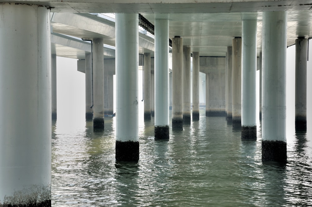
A large number of waterfront structures are supported on piles. The piles may be constructed of timber, concrete or steel sections. The adverse environment introduced by seawater, high humidity, high temperature and dry-wet cycles causes rapid deterioration of these structures. The most severe conditions are found in the splash zone area, which encompasses the portion of the pile between the lowand high-tide water levels.
The high concentration of chlorides in seawater allows it to penetrate and reach the reinforcing steel, even in high-quality concrete. As a result, the passive layer that normally protects steel is destroyed, making the corrosion of reinforcing or prestressing steel inevitable. Because corroded steel occupies a larger volume, it causes lateral pressure on the surrounding concrete that far exceeds the cracking strength of concrete. This results in cracking and spalling of the concrete cover, which in turn, accelerates the corrosion process.
The deterioration of concrete and the loss of cross sectional area of steel results in a reduction in the capacity of the pile. Consequently, a structural repair should not only address the reconstruction of the deteriorated and corroded materials, but more importantly it should restore the original strength of the pile. In some projects, for example in expansion of a port, it may even be necessary to strengthen the old piles to a higher capacity than the original pile.
GLASS FRP PILE JACKETS
Glass Fiber Reinforced Polymer (GFRP) materials being lightweight and durable have gained popularity in repair of piles in the last 20 years. Figure 1 shows a number of systems that are currently marketed in North America. These jackets are usually made of chopped glass mat impregnated with vinyl ester or polyester resin. They are typically supplied as two half-shells that are attached together in the field by straps, bolts or an epoxy adhesive to create a formwork around the pile; some versions are supplied with a single tongue and groove connection that are glued together in the field. There are several shortcomings with these jackets as discussed below.
 The chopped glass mat is fairly weak in tension. Figure 2 shows the tensile strength of six of the most popular jackets in the U.S. To protect manufacturers’ anonymity these have been designated as Jacket Type A through F. The tensile strength values are based on the data provided by the manufacturers and range from 10,000 to 24,000 psi.
When a concrete pile loaded in the axial direction approaches its failure, as the concrete crushes, it will dilate and will have a tendency to expand laterally due to Poisson’s effect. If the jacket is strong enough to resist this lateral expansion, the strength of the pile is increased tremendously. The problem with GFRP jackets is that not only the materials are weak, but they cannot fully develop their capacity either, since the jacket will fail prematurely at the bolted or glued tongue and groove seam. That is, these jackets will provide little if any confining pressure for the concrete pile.
It is well recognized that oxygen is the fuel to the corrosion process. Studies at University of Florida, for example, have demonstrated that when a concrete pile is encased in a jacket that prevents ingress of moisture or oxygen, the corrosion rate is significantly reduced. The GFRP jackets, having a seam along the side, will allow moisture and oxygen to penetrate and reach the concrete pile to fuel the corrosion of reinforcing steel.
From a constructability point of view, the GFRP jackets have to be ordered to size in advance, adding to the wait time before the project can begin. Any variation in size results in further delays in the project. Moreover, the large bulky jackets add to shipping charges and require large staging areas on the job site.
FRP LAMINATES
Following 25 years of research and development, the author has invented a new process where layers of carbon or glass fabric are saturated with resin and pressed together to create very thin sheets. The thickness of these sheets varies between only 0.01 to 0.025 inches; this has been a challenging feature of this invention to create such a thin and strong product. The sheets are supplied in rolls that are typically 4-ft wide by 200-ft long. This reduces shipping costs and planning time, since a sheet can be wrapped around a pile of virtually any size or shape! As shown in Figure 2, the tensile strength of these laminates is significantly higher than that of the GFRP jackets and ranges from 62,000 to 156,000 psi. The values in the figure are for a biaxial glass (BG), biaxial carbon (BC), and unidirectional carbon (UC).
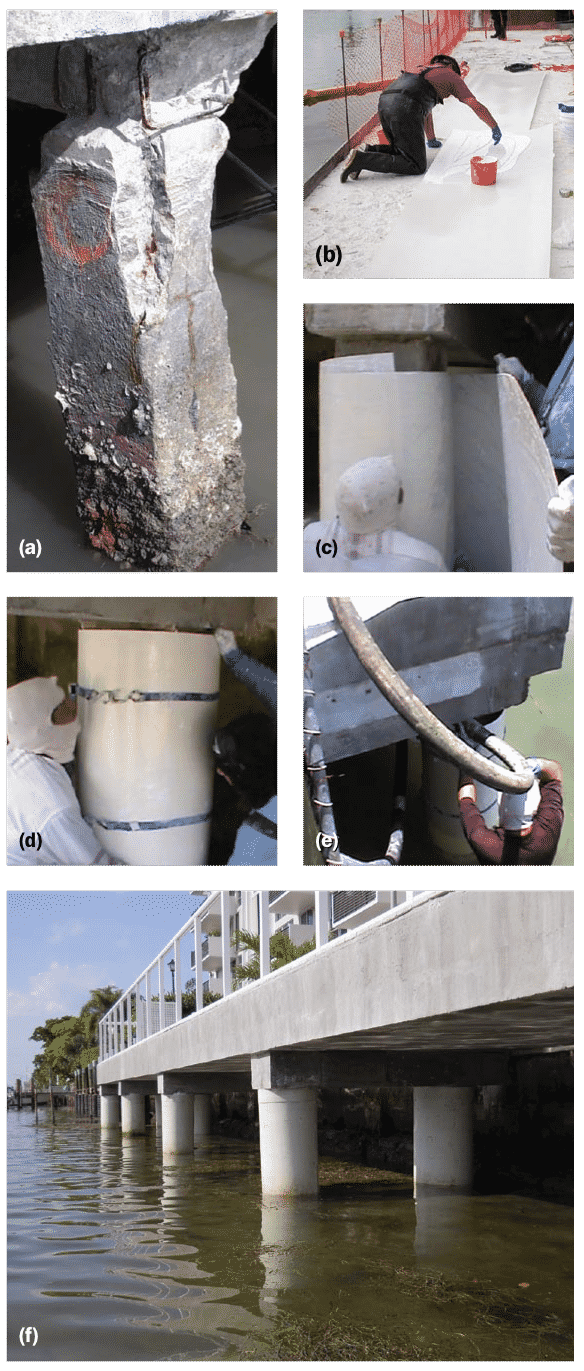
Standard repair procedure shown in Figure 3 requires creating a two-ply shell around the pile. For example, if the contractor wishes to create a jacket with a diameter of 18 inches (or circumference of 56 inches), he will cut a 10-ft long piece of the laminate. The 10 feet is calculated as 56+56+8 = 120 inches = 10 feet. That is, two times the perimeter plus an 8-inch extension beyond the starting point. This detail ensures that at all points around the pile, at least two layers of laminate will be providing confinement for the pile. The laminates can be easily cut to any length using a pair of scissors or a hand-held rotating saw.
For the above example, a 56+8=64 inch length of the laminate will be coated with a special epoxy adhesive paste provided that cures in water (Figure 3). The laminate is then wrapped around the pile, such that the second half which is coated with epoxy is bonded to the first half; the laminate can be easily adjusted and temporarily held using shrink wrap or ratchet straps. Since the laminate is not bonded to the pile, it is also free to slide up or down along the height of the pile. If the repair length is taller than 4 feet, an additional shell can be similarly created, overlapping and epoxied to the first shell by a few inches. The approximately 8-ft long shell can now be lowered into water and the process can be continued to create a very long shell with virtually no need for divers. Once the jacket is in its final position, the bottom of the annular space can be sealed and the annular space is filled with concrete or epoxy grout.
The jacket thus created in the field has no seam along its height. Therefore there is no chance for oxygen or moisture to penetrate through the jacket and reach the concrete. Furthermore, the combination of the high tensile strength of the laminate and the lack of any seam that allows full utilization of this high tensile strength, provides significant confinement and additional strength to the pile as detailed in the example.
What causes concrete piles to fail in waterfront structures, and how does corrosion contribute to the deterioration process?
Concrete piles in waterfront structures can fail due to the penetration of seawater, high humidity, and temperature fluctuations causing corrosion of reinforcing steel, leading to cracking, spalling, and a reduction in pile capacity.
What are the advantages of using FRP laminates over traditional GFRP jackets for repairing deteriorated concrete piles in marine environments?
FRP laminates offer higher tensile strength, reduced corrosion rates by preventing moisture and oxygen ingress, easier customization, and simplified construction processes compared to GFRP jackets, providing a more effective and efficient solution for pile repair in marine environments.

