Chapter 9 – Placement and Design of Concrete For Drilled Shafts
- Chapter 1 – Selection and Use of Drilled Shaft Foundations for Transportation Structures
- Chapter 2 – Site Characterization
- Chapter 4 – General Construction Methods
- Chapter 5 – Tools and Equipment
- Chapter 6 – Casings and Liners
- Chapter 8 – Rebar Cages
- Chapter 9 – Placement and Design of Concrete For Drilled Shafts
From Drilled Shafts: Construction Procedures and LRFD Design Methods by FHWA
9.1 INTRODUCTION
The construction of a drilled shaft foundation can be thought of as the fabrication of a reinforced concrete structure in-situ. This aspect of the manufacture of the foundation structure is often conducted under extremely challenging conditions with underwater placement of reinforcing and concrete at depths exceeding 100 ft below the ground surface. Concrete placement techniques and materials represent a critical aspect of the process and require thorough planning and design. The mix design, and the means and method of concrete placement are most often delegated to the contractor, with submittals required for approval by the engineer/owner/agency. It is imperative that all stakeholders in the process have a good understanding of the basic requirements and characteristics of drilled shaft concrete.
This chapter describes the placement of concrete for drilled shafts, and the design and testing of concrete mixes with emphasis on the unique requirements of drilled shaft concrete. This chapter will focus on the specific issues of greatest import to drilled shaft construction and performance, emphasizing the workability characteristics critical to success in this application. Testing for quality control and quality assurance during batching and concrete placement is described in this chapter; integrity testing of completed drilled shafts is described in Chapter 20.
9.2 BASIC CHARACTERISTICS OF DRILLED SHAFT CONCRETE
Because of the unique construction techniques used for drilled shafts compared to other reinforced concrete structures, the concrete used must be designed for the specific requirements of this application. The most unique and important of these involve the workability requirements for the fresh concrete during transport and placement operations. Oftentimes the mix must be transported long distances to a remote bridge site to be pumped long distances to then flow readily through a tremie and congested reinforcement under slurry to fill a hole which may be 10 ft diameter at depths exceeding 100 ft, and the mix may be required to stay fluid for periods of 4 to 8 hours or more in widely ranging ambient temperature conditions. In addition, the mix must consolidate under its own self weight without vibration and without segregation, excessive bleeding, or heat of hydration. A challenging set of circumstances to be sure, but not uncommon with modern drilled shaft construction.
Drilled shaft concrete and aspects of construction of drilled shafts related to concrete are discussed in ACI 336.1 (2001), which is recommended as parallel reading for this chapter. The publication “Design and Control of Concrete Mixtures” (Kosmatka et al, 2002) is appropriate background reading for the reader who is not familiar with concrete mixtures in general or with terminology related to concrete.
The basic characteristics of concrete for drilled shafts can be summarized as follows:
- Filling Ability: It is essential that the concrete have the ability to flow readily through the tremie to fill the shaft excavation and restore the lateral stress against the sides of the borehole. In some cases, the concrete may be placed to fill a casing and then the casing removed some minutes or hours later at which time the concrete must again flow laterally to displace fluids and fill the excavation. This objective can best be met by using concrete that is highly fluid and by ensuring that the reinforcement cage is designed to allow the concrete to pass through it.
- Passing Ability: The concrete must readily pass through the reinforcement without blocking. Even with a highly fluid mix, the aggregate size and gradation must be proportioned so that the concrete can pass through small openings without blocking.
- Self-weight Compaction: Vibration of concrete in a borehole is not possible (due to depths and time required) or desirable (due to underwater placement) in deep drilled shafts, and the concrete must fill and consolidate under self weight.
- Resistance to Segregation and Bleeding: The paste within the concrete mix should have a high degree of cohesion so that the coarse aggregate particles are evenly distributed through the mix without any tendency to segregate. Likewise, the water within the mix should remain distributed without a tendency to bleed and result in non-uniform properties or bleed water channels.
- Resistance to Leaching: When concrete is placed under a drilling fluid (slurry or water), there is inevitable contact between the concrete and the fluid. The mix must have a cohesive nature that is resistant to mixing with external fluid and leaching.
- Controlled Setting: With underwater placement or when casing must be withdrawn after completion of concrete placement, the drilled shaft concrete must retain its workability throughout the time required for completion of placement operations.
- Durability: The concrete cover on the reinforcement must provide low permeability so as to minimize the potential for corrosion of the reinforcing. If the subsurface environment is aggressive or can become aggressive during the life of the foundation, the concrete should be designed to have high density and low permeability so that the concrete is able to resist the negative effects of the environment.
- Low Heat of Hydration: For some large-diameter drilled shafts, the volume of concrete placed may be sufficient to require measures to prevent excessive heat of hydration as would be associated with mass concrete. The temperature of the mix can also be a concern during hot weather concrete operations. High in-place temperatures must be controlled so that conditions do not lead to delayed ettringite formation (which causes cracking and may result in loss of load carrying capacity) or that excessive thermal gradients do not produce thermal cracking.
- Appropriate Strength and Stiffness: The concrete must provide the strength and stiffness necessary to meet the structural performance requirements.In most cases, drilled shafts are not subject to high structural stresses within the concrete and so the strength demands are relatively ordinary compared to the extreme workability requirements cited above. The following section outlines recommended construction practices for concrete placement. A complete understanding of the concrete placement requirements during construction of drilled shafts is necessary in order to develop a mix design with the appropriate workability characteristics for the specific needs of a project.
9.3 PLACEMENT OF CONCRETE
Concrete placement in a drilled shaft excavation must be carefully planned and executed to meet the specific conditions associated with the different methods of construction described in Chapter 4. The following sections describe the procedures used with concrete placement in dry and wet excavations, and with the considerations necessary for temporary casing.
 9.3.1 Placement in a Dry Shaft Excavation
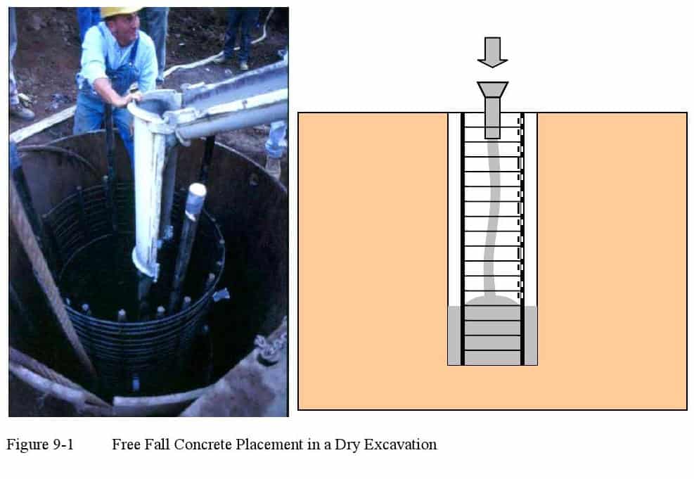
A dry excavation without removable casing provides the simplest conditions for concrete placement operations. In most cases, concrete can be placed by free fall methods so long as the concrete is directed down through the center of the shaft without directly hitting the reinforcing cage or the sides of the hole. The impact of the concrete against the reinforcement cage could produce distortion of the cage or segregation in the concrete. If concrete hits the sides of the hole, soil or debris could be knocked into the fresh concrete during placement.
The flow of the concrete in free fall should be directed to the center of the borehole and cage by a drop chute or other acceptable device to keep the stream of falling concrete centered in the hole. Laborers with shovels are not generally able to direct the stream of concrete adequately. A drop chute can be composed of a short section of relatively stiff or rigid pipe; flexible hose is not recommended because of the difficulty in directing the discharge from a flexible hose. In cases where the truck can locate very near the top of the shaft, the last section of the chute from the concrete truck can often be used to direct the flow as illustrated in Figure 9-1. Figure 9-2 illustrates a case in which the concrete was lifted to the top of the column reinforcing using buckets and placed into the dry excavation via the drop chute. In this example the drop chute is a simple stiff plastic tube attached to a funnel at the top. Note also that a tremie pipe (described in Section 9.3.3) may also be used as a simple drop chute if a dry shaft excavation is achieved.
9.3.1.1 Effects of Free Fall Placement of Concrete
Several detailed studies have been conducted to investigate the effects of free fall on drilled shaft concrete. Baker and Gnaedinger (1960) report a study on the influence of free fall on the quality of concrete. The concrete was placed in an excavation that was 36 inches in diameter and 80 ft deep. The concrete was guided at the top of the excavation and allowed to fall freely without striking the sides of the excavation. The design of the concrete called for a strength of 5,000 psi at 28 days. After the concrete had set for approximately two weeks, the drilled shaft was cored, and cores examined visually. An excavation was made to a depth of 50 ft along the side of the shaft, and the strength of the concrete was tested by use of a Schmidt hammer. Free fall was found not to result in any observable segregation of the mix, and the compressive strength of the concrete was not reduced.
Bru et al. (1991) describe studies made at the Laboratoies des Ponts et Chaussees in France in which cohesive concrete was allowed to fall freely for 30 ft without striking rebar or the side of the borehole. No evidence of strength loss in the concrete in the bottom 2 ft was observed based on wave velocity measurements.
Kiefer and Baker (1994) conducted a detailed parametric field study of the effects of free fall, in which the slump and coarse aggregate size of the concrete were varied, superplasticizers were used in some mixes and some drops were made through the reinforcing steel. The slump varied from 4 to 8 inches, the coarse aggregate size varied from 5/8 to 1-1/4 inch; a retarder was used in the mix; and the water to cementitious material (w/cm) ratio was held constant at 0.53. The diameter of the cage was 36 inches and maximum drop height was 60 ft. There were 5 to 5-1/3 sacks of Portland cement and a weight of fly ash equivalent to about 1 sack of Portland cement per cubic yard, together with enough fine aggregate to make a cohesive concrete mix. Core samples were recovered and Schmidt hammer tests were performed, and access shafts were made to permit observation of the concrete in the constructed shafts. No loss in compressive strength or segregation in the concrete was observed when the concrete was dropped centrally inside the cages with any of the mix variations indicated above. In fact, there was a slight positive correlation between drop height, density of the cores and compressive strength, suggesting that the impact of the free-fallen concrete drove out air, produced denser concrete, and thereby produced stronger concrete. Similar results were obtained when the w/cm ratio was reduced and high-range water reducers were added. Dropping the concrete in such a manner that it fell through the rebar cage did not, in most cases, result in reduced strength or increased segregation, although this action did result in moving the cage off position and some contamination of the concrete as it traveled down the soil sides of the borehole.
It appears, therefore, that concrete can be dropped freely for distances up to about 80 ft without problems as long as the concrete does not strike the cage or the borehole wall. Kiefer and Baker (1994) report that keeping the concrete stream away from the rebar cage was not a problem for a depth-to-cage-diameter ratio of 24 or less, and they suggest that free fall could be used to a depth of 120 ft in a 5-ft diameter cage based on these tests and construction experiences with large-diameter, deep drilled shafts in the Chicago area.
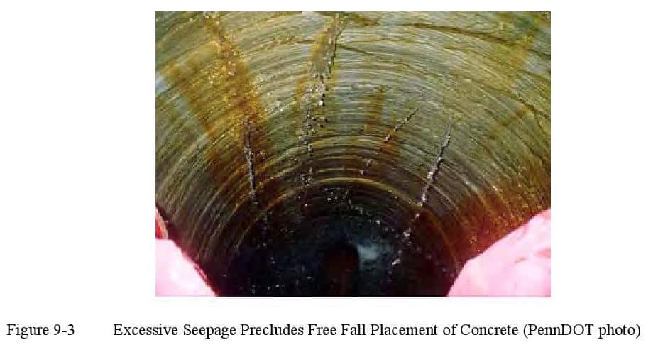
If the shaft excavation is not completely dry and the concrete is placed by free fall, then there will be mixing of the concrete with the water which is present at the base of the shaft. The result would be a concrete mix with excessive water or perhaps even a zone of washed aggregate if a substantial amount of water is present. The contractor can often pump out water so that an unobjectionable small (less than 3 inches) depth remains, and this method is sufficient so long as there is not a substantial inflow of water. In general, a flow into the excavation producing more than 12 inches of water per hour (1 inch per 5 minutes) is considered excessive. If excessive seepage occurs as shown in Figure 9-3, it is necessary to flood the excavation to avoid the inflow, and place concrete using a wet method as described subsequently. It may not be sufficient to simply use a tremie without flooding the excavation to control inflow, because water inflow may have a pressure head greater than the head of concrete during the placement operations and thus could result in the formation of flow channels of water into or through the fresh concrete. By flooding the excavation and placing concrete with a tremie, the higher fluid head within the shaft excavation will maintain a positive outward direction of flow until the fluid concrete has filled the hole.
-
 SPW911 Sheet Pile Design Software
Rated 5.00 out of 5$150.00 – $599.99Price range: $150.00 through $599.99
 -
 Sheet Pile Design (PDF Download)
Rated 5.00 out of 5$89.00
 -
 Pile Driving (PDF Download)
$89.00
-
 Marine Construction Volumes 1 & 2 (PDF Download)
$157.00
-
 Pile Driving (Book)
$89.00


