Chapter 5 – Tools and Equipment
- Chapter 1 – Selection and Use of Drilled Shaft Foundations for Transportation Structures
- Chapter 2 – Site Characterization
- Chapter 4 – General Construction Methods
- Chapter 5 – Tools and Equipment
- Chapter 6 – Casings and Liners
- Chapter 8 – Rebar Cages
- Chapter 9 – Placement and Design of Concrete For Drilled Shafts
From Drilled Shafts: Construction Procedures and LRFD Design Methods by FHWA
5.1 INTRODUCTION
Most contracts for drilled shaft construction establish that the means and methods are the contractor’s responsibility. Therefore, the final choice of the types of drilling rigs and drilling tools that are to be used to make excavations for drilled shafts on a specific project are almost always chosen by the contractor. These choices are made based upon:
- The subsurface conditions that are encountered as a part of the site investigation and presented to bidders via the contract documents. It is therefore critical that sufficient design-phase geotechnical investigations be performed to appropriately characterize the existing subsurface conditions. Also, it is essential that the conditions encountered in the site investigation be conveyed as openly and clearly as possible in the geotechnical report and that this information is available to prospective bidders. If possible, rock cores and soil samples should be made available for inspection by bidders. On large or complex projects (particularly design-build projects), owners may make additional borings upon the request of bidders or bidders may choose to make additional borings or test holes for their own use.
- Additional indications of subsurface conditions that may be revealed as a part of a site visit by the prospective bidder. Therefore, it is important that the site be accessible to potential contractors. In some cases it may be warranted to perform a pre-bid exploratory shaft excavation so that bidders have an opportunity to directly observe conditions in a full size shaft excavation.
- The contractor’s personal experience in similar geologic conditions.
- The contractor’s available equipment and experience with that equipment.
- The experiences of other contractors in the local area on similar projects and under similar geology, provided that information is available to the contractor. Where a transportation agency has documented information available on previous drilled shaft projects, this information can be extremely valuable in terms of minimizing uncertainty and contingency costs in the bid and in avoiding potential claims. There is great value in post-contruction documentation of “lessons learned” for future use by transportation agencies.The choice of rigs and tools is critical to the success of a project. Sometimes an apparently minor change in a drilling tool can change the rate of excavation dramatically. Because of the importance of selecting proper tools and equipment, it is critical for both engineers and inspectors to understand the general types of rigs and tools available in the United States. Although the burden of risk in the choice of specific tools and equipment is typically the contractor’s responsibility, the list above underscores the importance of the engineers and owners in understanding tools and equipment and the information needed by the contractor to make an informed decision.The following sections describe the drilling machines and tools for excavation of drilled shafts.
The machines used for drilling shaft excavations have evolved over the years from primitive mechanical systems (e.g., Figure 5-1 from the 1930’s) supplemented by heavy reliance on manual excavation to sophisticated and powerful hydraulic machines with extensive in-cab instrumentation and controls. This section provides an overview of the broad range of drilling machines available in current (2009) U.S. practice.
5.2.1 Overview of Rotary Systems
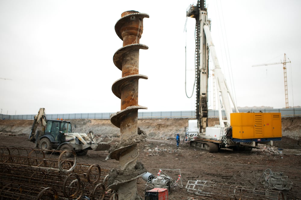
Most excavations for drilled shafts in the United States are made by some type of rotary-drilling machine. The machines vary greatly in size and in design as well as by the type of machine on which the drilling rig is mounted. The machine transmits force from the power unit through the rotary to a kelly bar to the tool attached to the end of the kelly as illustrated on Figure 5-2.
The capacity of a drilling rig is often expressed in terms of the maximum torque that can be delivered to the drilling tools and the “crowd” or downward force that can be applied. Other factors can have great impact on the efficiency of the rig in making an excavation, particularly the type and details of the drilling tools, but the torque and crowd are important factors affecting the drilling rate.
Torque and crowd are transmitted from the drilling rig to the drilling tool by means of a drive shaft of steel, known as the kelly bar, or simply the “kelly.” The drilling tool is mounted on the bottom of the kelly. Kellys are usually either round or square in cross section, and may be composed of a simple single piece (up to about 60 ft long) or may telescope using multiple inner sections to extend the depth to which the kelly can reach. The square kelly bars often require a worker to insert a pin to lock the outer bar to the inner telescoping kelly piece, whereas the round kellys often include an internal locking mechanism. In some rigs the weight of the kelly and the tool provides the crowd. In others, hydraulic or mechanical devices are positioned to add additional downward force during drilling.
Specific details relating to the capabilities of individual drilling machines are readily available on the websites of equipment manufacturers. A contractor will normally provide these details as a part of the drilled shaft installation plan for a specific project.
5.2.2 Mechanical vs Hydraulic Systems
The drilling machines used in the drilled shaft industry are typically powered by either a mechanical system or by hydraulic power. Examples of each type are shown in Figure 5-3.
A typical mechanical drive system delivers power to the rotary via a direct mechanical drive shaft or sometimes a right angle drive from a multiple speed transmission. This type of system has a long history of use, is mechanically simple, and is relatively lightweight. Most lightweight truck-mounted drill rigs use direct drive mechanical systems. Large crane attachments as shown in Figure 5-2 are also direct drive mechanical systems.
Recent years have seen an increase in the use of hydraulic systems to deliver force to the rotary table. The potential high pressures available in modern hydraulic systems can provide rigs with a higher torque range, and the use of the hydraulic drive allows the rotary to move up and down the mast rather than restrained to a location fixed by the drive system. The movable rotary provides versatility in that the rotary can elevate above casing and even be used to install casing. Hydraulic rigs are sometimes heavier and more expensive than a similar size mechanical machine.
Mechanical drive systems often apply crowd through a pull-down system applied to a drive bar atop the kelly, in which the drive bar is guided within the leads as it travels up and down the mast. Although the same crowd system can be applied to a hydraulic driven kelly, more often the crowd in a hydraulic system is applied through the rotary.
5.2.3 Methods of Mounting Drilling Machine
The drilling machine must be mounted on some type of carrier in order to drill and move about the site. The type of carrier has an effect on the versatility of the machine and the efficiency of the overall operation. Drill rigs may be mounted on trucks, crawlers, excavators, cranes, or may even be designed to operate directly as a top drive unit mounted onto a casing. The following sections provide a brief description of drill rigs by methods of mounting the machine.
5.2.3.1 Truck Mounted Drilling Machines
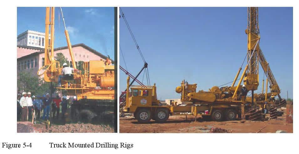
Mobility is the greatest advantage of truck-mounted drilling machines, which can range widely in size and drilling capabilities. As shown in Figure 5-4, truck-mounted rigs can range from small, extremely mobile rigs most suited to small holes to large, heavy rigs capable of drilling rock. If the site is accessible to rubber-tired vehicles and conditions are favorable for drilling with truck-mounted rigs, construction of drilled shafts can be accomplished very efficiently with these machines. With the mast or derrick stored in a horizontal position, lighter units can move readily along a roadway. The truck can move to location, erect the derrick, activate hydraulic rams to level the rotary table, and begin drilling within a few minutes of reaching the borehole location.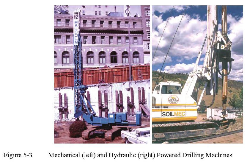
Truck-mounted rigs are normally mechanically-driven with a fixed rotary, and therefore may have limited capability to reach over tall casing or to handle tall drilling tools. The space below the rotary table can be increased by placing the rig on a ramped platform, but this procedure is obviously slow and expensive and would be used only in unusual circumstances. However, some truck-mounts are now supplied with a hydraulic sliding rotary which can overcome many of the limitations of older truck-mounted rigs.
While the truck-mounted unit has a secondary line with some lifting capacity, that capability is necessarily small because of the limited size of the derrick. The drilling tools can be lifted for attachment to and detachment from the kelly, but, if a rebar cage, tremie or casing must be handled, a service crane is usually necessary. Some truck rigs can handle light rebar cages and tremies of limited length.
5.2.3.2 Crane Mounted Drilling Machines
A power unit, rotary table, and kelly can be mounted separately on a crane of the contractor’s choice, as shown in Figure 5-5. Crane mounted drill rigs can have substantial capabilities and versatility on a bridge project, especially over water. The crane-mounted machine is obviously less mobile than a truck unit. Mobilization to the jobsite generally requires “rigging” or assembly of the equipment with significant cost and effort.
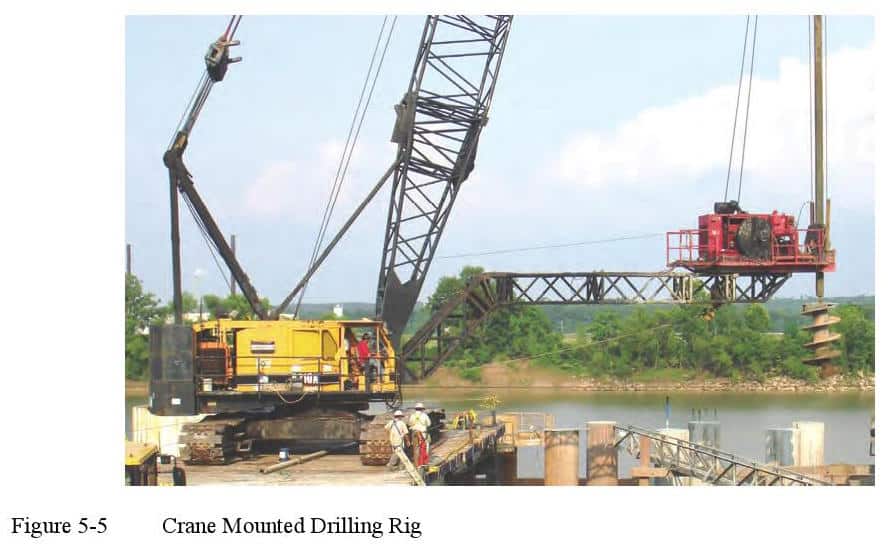 Power units of various sizes can be utilized to supply large torque at slow rotational speeds to the drilling tool. Usually, the downward force on the tool is due to the dead weight of the drill string, but the dead weight can be increased by use of heavy drill pipe (drill collars), “doughnuts,” or a heavy cylinder. Special rigging is available for crane machines that will apply a crowd for drilling in hard rock. The cross-sectional area of the kelly can be increased to accommodate high crowds.
The framework or “bridge” that is used to support the power unit and rotary table can vary widely. The rotary table may be positioned 75 ft or more from the base of the boom of a crane by using an extended mount. The ability to reach to access the hole from a distance makes crane mounted machines very attractive in marine construction when working from a barge or work trestle. The bridge for the drilling unit can also be constructed in such a way that a tool of almost any height can fit beneath the rotary table. Therefore, crane-mounted units with high bridges can be used to work casing into the ground while drilling or for accommodating tall drilling tools.
A service crane or the drilling crane itself is used on the construction site for handling rebar cages, tremies, concrete buckets and casings. The secondary lift line on the drilling crane can be used for common lifting by tilting the derrick forward and away from the rotary table, thus making the crane- mounted drilling unit a highly versatile tool.
5.2.3.3 Crawler Mounted Drilling Machines
Crawler mounted drilling machines may be less mobile than truck mounted equipment for accessible sites, but can provide excellent mobility on the jobsite. Compared to a crane mounted rig, the drilling equipment is usually a permanent fixture on the crawler with a fixed mast serving as the lead for the rotary or kelly guide system. The crawler mount is the most common system used for hydraulic powered rigs, although it is also a popular system for conventional mechanical rigs; both types were shown mounted on crawler equipment in Figure 5-3.
Lightweight crawler mounted drilling machines can be extremely versatile for work on difficult to access sites for applications such as slope stabilization, sound wall foundations, and foundations for signs, towers, or transmission lines. An example of a mobile crawler mounted drill rig is shown in Figure 5-6.
5.2.3.4 Excavator Mounted Drilling Machines
An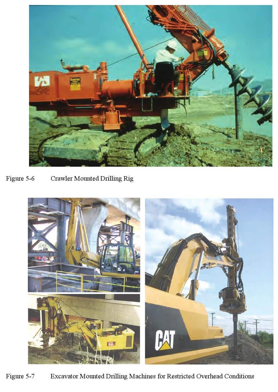 other type of crawler mount that has advantages for some special applications is the placement of the drilling machine on the arm of an excavator as shown in several examples in Figure 5-7. These rigs are almost always hydraulic, utilizing the hydraulic system common on an excavator. The advantage of such a mount is that the rig can reach a difficult to access location with low headroom or with limited access immediately adjacent to the hole. Low headroom equipment is often advantageous for applications such as a sound wall where utility lines are overhead or when installing shafts below or very near an existing bridge structure. The use of low headroom equipment has obvious limitations in terms of the depth and size of hole that can be drilled efficiently. Reduced productivity in drilling under low overhead conditions will affect costs.
5.2.3.5 Oscillator/Rotator Systems
Oscillator and rotator systems are hydraulic-driven tools for advancing and extracting casing. The casing often is a segmental pipe with bolted joints. The oscillator or rotator grips the casing with powerful hydraulic-driven jaws and twists the pipe while other hydraulic cylinders apply upward or downward force. An oscillator twists back and forth, while a rotator (a more expensive machine) can rotate the casing through a full 360° when advancing casing. An example of an oscillator is shown in Figure 5-8 and a rotator is shown in Figure 5-9.
The tremendous twisting force of these powerful machines must be resisted by a reaction system. The oscillator in Figure 5-8 is mounted on a template and frame supported by four steel pipe piles. The rotator torque in Figure 5-9 is resisted by an arm extending to a large crane, and this crane uses dead weight to provide friction of the tracks on the pile-supported platform below. The vertical force acting to push the casing down is normally restricted to the dead weight of the casing plus machine, but the vertical force to pull the casing out (which may be much larger, after the casing is embedded into the soil and may be partially or completely filled with concrete) must be resisted by a reaction system or the bearing capacity of the ground surface. The axial and torque capacity of the entire reaction system must be carefully designed (normally by the contractor) to be sufficient for the machine to work efficiently.
Excavation within the casing is often made using a clam or hammergrab, although a rotary drilling machine can be mounted on the casing to operate as a top-drive unit. It is also possible to excavate sand within the casing using a dredge pump or airlift system. Care must be used so as not to dredge sand below the casing, and as with any type of circulation drilling (discussed in the following section), fluid must be pumped into the casing sufficiently fast as to maintain a head of water. The oscillator/rotator systems are often used with a fully cased hole, although the drilled shaft excavation can be extended into rock or stable soils below the bottom of the casing.
5.2.3.6 Casing Mounted Top-Drive Systems
Casing mounted top-drive systems are used with reverse circulation drilling, since the rotary machine is mounted on the casing itself. The basic principle of reverse circulation drilling was described in Chapter 4. The full-face rotary cutting head breaks up the soil or rock and an airlift system pumps the drilling fluid containing spoil away from the cutting surface. The drilling fluid is then circulated through a desander and/or settling basin, and returned to the shaft excavation. Slurry or water may be used as the drilling fluid, depending upon the stability of the hole and the length of casing. Examples of top-drive systems are shown in the photos of Figure 5-10. The photo on the left shows the machine during operation with the circulation system in place; cuttings are lifted from the bottom of the excavation through the central pipe, through the swivel at the top of the drill string, and through the discharge hose to a spoil barge. As the hole is advanced, short sections of drill pipe are added. The photo at right shows the top drive system rotated from vertical so that the drill string can be removed or inserted. Cutting heads are shown on Figure 5-11.
The top-drive system mounted on the casing must react against the casing during drilling, so the casing must be sufficiently embedded into firm soil to provide a stable platform on which the machine can work. The excavation below the casing must be stable not only for support of the casing, but also to avoid the collapse of debris into the hole above the cutting head that could make the cutting head difficult or impossible to retrieve. The casing may be installed using a vibratory or impact hammer, or using an oscillator/rotator.
5.2.4 Other Excavation Systems
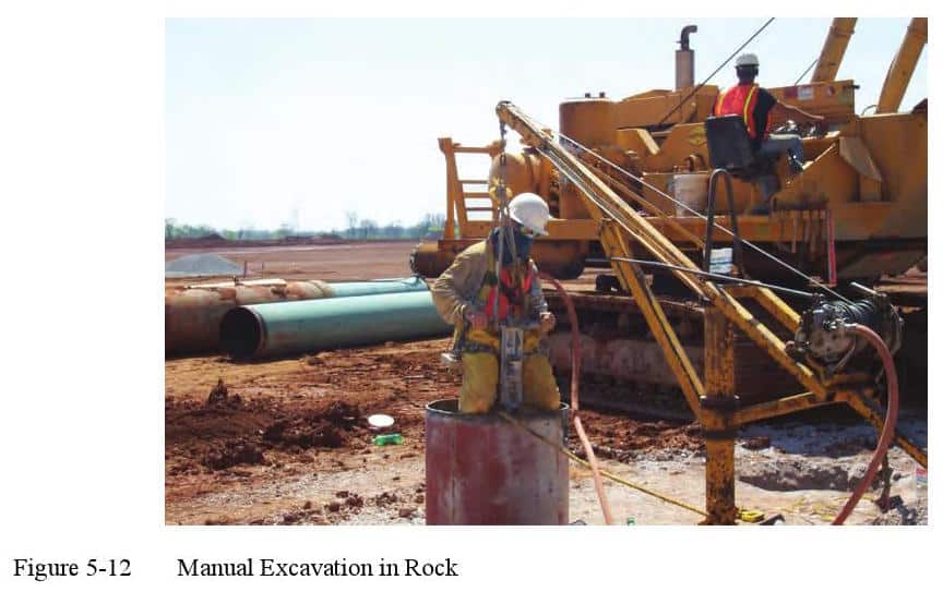 Although the vast majority of drilled shafts are excavated using rotary machines, other systems may be employed to advance an excavation into the subsurface for a wall or foundation. These include manual techniques and excavation using grab tools or slurry wall equipment.
Manual excavation (Figure 5-12), i.e., vertical mining, has been employed for many years and is still a viable technology in some circumstances, such as for underpinning of existing structures. Excavation using workers below ground obviously requires great attention to safety considerations and is usually quite expensive compared with alternatives. Manual excavation is usually only considered where mechanized equipment is ineffective or where the location is inaccessible, such as to remove a boulder or rock or in a confined space where a heavy machine cannot be positioned. For dry excavations into very strong rock, there may be circumstances where hand labor is cheaper and faster. If bells are to be cut into shale with limestone stringers, for example, it may be desirable for workers to excavate the bell by hand with the use of air hammers. Hand excavation is also sometimes employed when it is necessary to penetrate steeply sloping rock, as in a formation of pinnacled limestone, where ordinary drilling tools cannot make a purchase into the rock surface.
Safety precautions must be strictly enforced when hand mining is employed. The overburden soil must be restrained against collapse, the water table must be lowered if necessary, and fresh air must be circulated to the bottom of the hole.
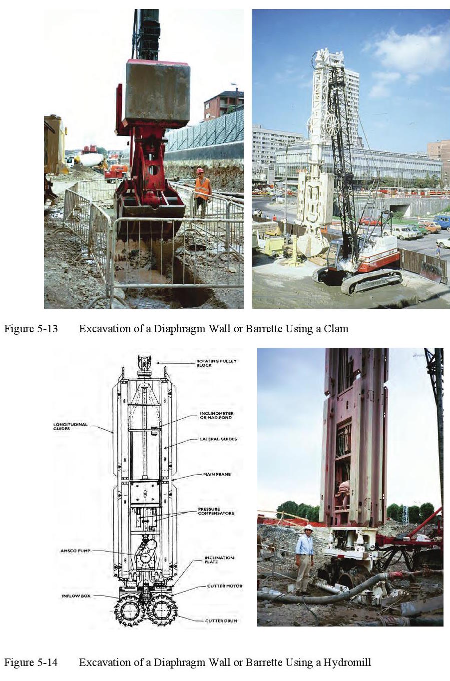
Other non-rotary excavation techniques may include the use of a grab or clam or hydromill, as in the construction of rectangular diaphragm wall panels. When used as a foundation, an individual panel is often referred to as a “barrette”. These panels can be efficiently oriented to resist large horizontal shear and overturning forces in addition to axial loads, and can even be post-grouted to enhance capacity. The use and testing of barrette foundations in Hong Kong is summarized by Ng and Lei (2003). A barrette is typically excavated under slurry to maintain stability of the excavation.
Photos of a clam system are shown in Figure 5-13; these may have a hydraulically controlled guide system to maintain alignment. Photos of a hydromill (or hydrofraise, as it is known in Europe) are illustrated in Figure 5-14. A hydromill or “cutter” is typically used to excavate rock, and cuts the rock with two counter-rotating wheels at the base of the machine. The excavated materials are lifted from the cutting face using an airlift or pump to circulate the slurry similar to the reverse circulation drill described in Section 5.2.3.6.
Rodless drilling machines have been developed in Japan that can be used in certain cases to solve difficult problems. One type that has been used to excavate circular holes consists of down-the-hole motors that drive excavating cutters that rotate in a column of bentonite drilling slurry. The cutters are designed to gouge the soil from the bottom of the excavation and push it to the center of the excavation, where it is then sucked into a flexible return line with the slurry and transported to the surface. The machine is handled with a cable; therefore, it is not necessary to have a high derrick. Other versions of the rodless drill (termed the “Mach Drill” by the manufacturer) include a series of hydraulically-operated hammers with button teeth that pulverize the rock and rotate to push the pulverized rock to the center of the excavation, where the rock fragments are removed by the reverse circulation process.
5.2.5 Summary
This section outlines what may appear to be a dizzying array of choices of machines for excavating a drilled shaft. The variety of machines available to contractors reflects the maturation of the foundation drilling industry and the development of specialized equipment to optimize productivity for particular applications. The range of mounting systems for the drilling machines and torque and crowd capabilities of modern equipment has extended the size, depth, and potential applications of drilled shaft foundations far beyond those considered feasible a few decades ago. Still, the basic concept used to construct the majority of drilled foundations for transportation structures is that of a simple rotary drilling machine turning a tool at the bottom of a hole and removing soil or rock one auger or bucketful at a time. Although the capabilities of the drilling machine are critical to the ability of the constructor to complete the drilled shaft excavation to the size and depth required, the choice of drilling tools is often as (or more) important to the productivity of the excavation process. Drilling tools are discussed in the following section.
-
 SPW911 Sheet Pile Design Software
Rated 5.00 out of 5$150.00 – $599.99Price range: $150.00 through $599.99
 -
 Sheet Pile Design (PDF Download)
Rated 5.00 out of 5$89.00
 -
 Pile Driving (PDF Download)
$89.00
-
 Marine Construction Volumes 1 & 2 (PDF Download)
$157.00
-
 Pile Driving (Book)
$89.00


