Chapter 2 – Site Characterization
- Chapter 1 – Selection and Use of Drilled Shaft Foundations for Transportation Structures
- Chapter 2 – Site Characterization
- Chapter 4 – General Construction Methods
- Chapter 5 – Tools and Equipment
- Chapter 6 – Casings and Liners
- Chapter 8 – Rebar Cages
- Chapter 9 – Placement and Design of Concrete For Drilled Shafts
From Drilled Shafts: Construction Procedures and LRFD Design Methods by FHWA
2.1 INTRODUCTION
Site characterization is the process of defining the subsurface soil and rock units and their physical and engineering properties. For drilled shafts, the information obtained is used for two general purposes: (1) analysis of resistances and load-deformation response, which determines the overall design, and (2) construction feasibility, costs, and planning. Thorough site characterization makes it possible to design reliable, economical, and constructible drilled shaft foundations that will meet performance expectations. Inadequate site characterization can lead to uneconomical designs, construction disputes and claims, and foundations that fail to meet performance expectations. In the LRFD design approach, uncertainty associated with geomaterial engineering properties is taken into account through resistance factors. Therefore, the site characterization process must be sufficient to define the variability of soil and rock engineering properties used in the LRFD design methods presented in subsequent chapters of this manual.
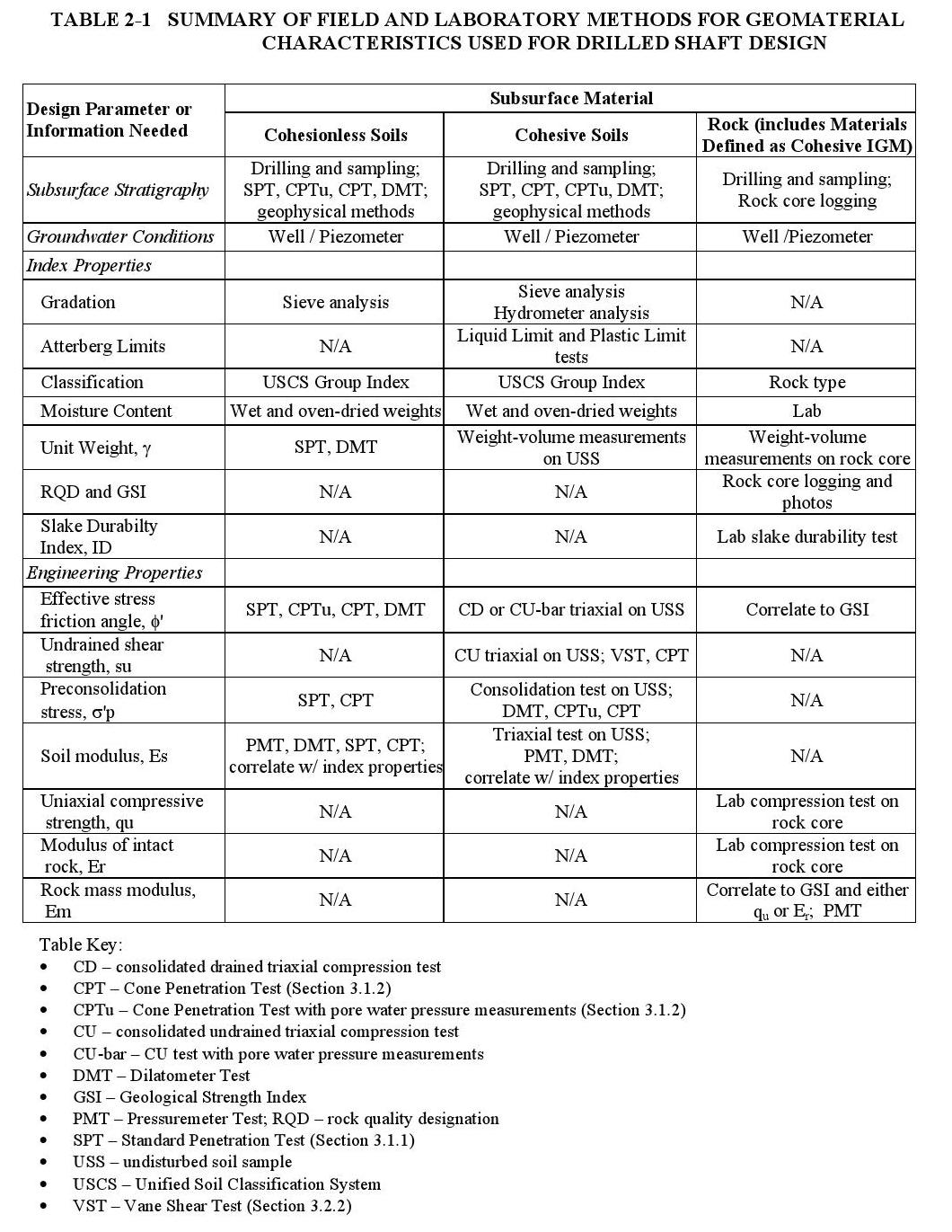
Table 2-1 summarizes the information needed for design of drilled shafts. For each characteristic or property and for each type of geomaterial, the means or method(s) used to obtain the information are identified. The information required for design of drilled shafts can be divided into three general categories: (1) subsurface stratigraphy and groundwater conditions, (2) index properties and classification of geomaterials, and (3) specific engineering strength and deformation properties. Additional information required specifically for constructability is considered in Section 2.3.4. This chapter describes the general approach to site investigation with a focus on responsibilities of the geotechnical engineer, how to implement a phased investigation program, methods of field exploration and sampling, and preparation of geotechnical reports. Chapter 3 presents a more in-depth description of methods used to determine the specific engineering properties used in the design equations and listed in Table 2-1. In addition, some design equations are based on empirical correlations between foundation resistances and measurements from in-situ tests. These are discussed in the appropriate design chapters on lateral loading (Chapter 12) and axial loading (Chapter 13), and in Appendix B (Special Geomaterials).
Article 10.4 of the AASHTO LRFD Bridge Design Specifications (AASHTO, 2007) has provisions for site investigations and establishing soil and rock properties for foundation design. Additional detailed treatment of specific methods is available from several sources. The U.S. Federal Highway Administration has developed reference documents dealing with basic soil mechanics, site characterization, and evaluation of soil and rock properties for geotechnical applications to transportation facilities. These include Mayne et al. (2001), Sabatini et al. (2002), and Samtani and Nowatzki (2006).
2.2 ROLE OF THE GEOTECHNICAL ENGINEER
Implementation of an effective site characterization program requires the direct participation of an experienced geotechnical engineer (or engineering geologist) with a thorough understanding of subsurface investigation techniques, foundation design procedures, and drilled shaft construction technology. As a member of the design team for a bridge or other structure, it is the responsibility of the project geotechnical engineer to direct the collection of existing data, conduct field reconnaissance, initiate the subsurface investigation, and to review its progress. It is also important that the geotechnical engineer be involved at the earliest stages of project development to define geotechnical issues that may impact foundation selection and location, and because geotechnical input is necessary throughout the process, from site selection to completion of foundation construction.
Once the data from the field investigation and laboratory testing program have been obtained, the geotechnical engineer is responsible for reduction and interpretation of these data, the definition of subsurface stratification and groundwater conditions, selection of appropriate soil and rock design parameters, and presentation of the investigation findings in a geotechnical report. The design team uses this acquired subsurface information in the analysis and design of drilled shaft foundations, for construction estimates and planning, and if necessary, to evaluate construction claims.
2.3 SITE CHARACTERIZATION PROGRAM
The scope of a site characterization program is determined by the level of complexity of the site geology, foundation loading characteristics, size and structural performance criteria of the bridge or other structure, acceptable levels of risk, experience of the agency, constructability considerations, and other factors. Some of the information needed to establish the scope of site characterization may only be known following a preliminary study of the site. For this reason, site investigations for drilled shaft projects may be carried out through a phased exploration program. This might typically include the following stages: (1) collection of existing site data, (2) a field reconnaissance stage, and (3) a detailed site exploration stage. Further investigation stages can be considered if there are significant design changes or if local subsurface complexities warrant further study. When properly planned, this type of multi-phase investigation provides sufficient and timely subsurface information for each stage of design while limiting the risk and cost of unnecessary explorations. In the overall design process for drilled shafts as presented in Chapter 11 (see Figure 11-1), the collection of existing data and field reconnaissance comprise Step 2: Define Project Geotechnical Site Conditions. The detailed site exploration constitutes Step 4: Develop and Execute Subsurface Exploration and Laboratory Testing Program for Feasible Foundation Systems. Additional site exploration could be required during the construction phase in some cases.
2.3.1 Data Collection
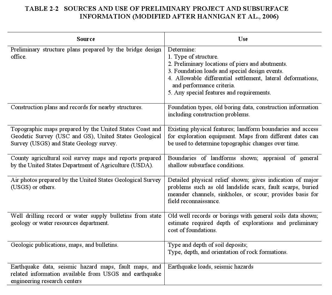
This stage involves collecting all available information pertaining to the site and the proposed structure, as summarized in Table 2-2. The primary source of information concerning the structure will be the Bridge and Structures Office of the state or local transportation agency. Any preliminary plans developed by the structural engineer should be studied and the geotechnical engineer should coordinate directly with the structural engineer and other project staff, preferably through periodic meetings with the design team.
Subsurface information targeted for data collection includes site geology and any existing specific geotechnical information. Site geology refers to the physiography, surficial geology, and bedrock geology of the site. Sources of existing data include: geologic and topographic maps, geologic reports and other publications, computer data bases, aerial photos, borings at nearby sites, previous construction records, and consultation with other geo-professionals. Many references are available that provide detailed information on sources and applications of existing data to geotechnical site characterization (NAVFAC, 1982; Mayne et al., 2001). Table 2-2 identifies sources of existing information and how each source can be used as part of a site study.
The geologic and geotechnical data obtained from the data collection study are used to establish anticipated site conditions and feasibility of various foundation types, make preliminary cost estimates, identify potential problems, and to plan the more detailed phases of site exploration. Following the data collection study, the geotechnical engineer is better prepared for the field reconnaissance stage of the investigation.
2.3.2 Field Reconnaissance
One or more site visits by the geotechnical engineer, with “plan-in hand” and accompanied by the project design engineer, if possible, is a necessary step in the site characterization process. Site visits provide the best opportunity to observe and record many of the surface features pertaining to access and working conditions and to develop an appreciation of the geologic, topographic, and geotechnical characteristics of the site. Site visits might provide evidence of surface features that will affect construction. A partial listing of factors to be identified includes the following:
-
- Restrictions on points of entry and positioning of construction equipment and exploratory drilling equipment, such as overhead power lines, existing bridges, and restricted work areas.
- Existence of surface and subsurface utilities and limitations concerning their removal, relocation, or protection.
- Locations of existing structures on the site and on adjacent sites. Descriptions of the as-built foundations of those structures must be obtained if it can be reasonably expected that subsurface ground movements could occur at the locations of those foundations due to drilled shaft construction.
- Locations of existing structures on the site and on adjacent sites. Descriptions of the as-built foundations of those structures must be obtained if it can be reasonably expected that subsurface ground movements could occur at the locations of those foundations due to drilled shaft construction.
- Locations of trees and other vegetation, and limitations concerning their removal or damage.
- Possibility of subsurface contamination, e.g., due to abandoned underground petroleum tanks or old landfills.
- Presence of surface water.
- Fault escarpments, boulders, hummocky ground, and other surface features that may suggest subsurface conditions.
- Comparisons of initial and final surface contours of the site.
- Condition of the ground surface that might be reasonably expected at the time of construction as related to trafficability of construction equipment.
- Restrictions on noise and/or other environmental conditions.
Ground geologic surveys may also be conducted as part of a reconnaissance study at sites where geologic hazards exist (e.g., landslides) or where surface outcrops can provide beneficial information. In these surveys, engineering geologists record observations on topography, landforms, soil and rock conditions, and groundwater conditions. Where bedrock is exposed in surface outcrops or excavations, field mapping can be an essential step to obtaining information about rock mass characteristics relevant to design and construction of rock-socketed shafts. A qualified engineering geologist or geotechnical engineer can make and record observations and measurements on rock exposures that may complement the information obtained from borings and core sampling. Rock type, hardness, composition, degree of weathering, orientation and characteristics of discontinuities, and other features of a rock mass may be readily assessed in outcrops or road cuts. Guidance on detailed geologic mapping of rock for engineering purposes is given in FHWA (1989), Murphy (1985), and ASTM D 4879 (ASTM, 2000). Photography of the rock mass can aid engineers and contractors in evaluating rock mass characteristics or potential problems associated with a particular rock unit.
After completing the data collection study and site reconnaissance, the geotechnical engineer should be able to identify the overall foundation design and construction requirements of the project. Feasible foundation types should be determined at this stage and it is assumed in the remainder of this chapter that drilled shafts have been selected for further investigation. The types of geotechnical data needed and potential methods available to obtain the needed data are identified and used to plan the subsequent phases of the investigation.
2.3.3 Detailed Field Investigations
This stage provides the site-specific information needed for design and construction of drilled shafts. Methods include geophysical surveys, drilling and sampling, field testing, and laboratory testing. In-situ and laboratory testing for determination of soil and rock engineering properties are covered in greater detail in Chapter 3. For major structures it is common practice to divide the field exploration into two phases. Initially, borings performed at a few select locations and geophysical tests are used to establish a preliminary subsurface profile and thus identify key soil and rock strata. Following analysis of the preliminary boring data, additional borings are then performed to fill in the gaps required for design and construction. A staged investigation program provides sufficient information for preliminary design, but defers much of the cost for the site investigation until the structure layout is finalized.
It is assumed that the project structural engineer has developed a preliminary plan prior to this stage in the investigation. The geotechnical engineer uses the preliminary plan for the bridge or other structure to establish the locations of geophysical surveys and locations, depths, type, and number of borings to be performed. In cases where the investigation is being done for a building, the designers should provide the layout and footprint of the building, plans, and any column and wall loads. Retaining wall or slope stabilization projects require preliminary plans showing the location of drilled shaft walls in plan view and cross-section including elevations.
2.3.3.1 Geophysical Surveys
Geophysical methods, in conjunction with borings, can provide useful information about the stratigraphy and properties of subsurface materials. Basic descriptions of geophysical methods and their application to geotechnical engineering are given by Sirles (2006) and FHWA (2008a).
The most frequently applied geophysical methods for drilled shaft foundation sites are seismic refraction and electrical resistivity. Seismic refraction is based on measuring the travel time of compressional waves through the subsurface. Upon striking a boundary between two media of different properties the propagation velocity is changed (refraction). This change in velocity is used to deduce the subsurface profile. Figure 2-1(a) illustrates the basic idea for a simple two-layer profile in which soil of lower seismic velocity (Vp1) overlies rock of higher seismic velocity (Vp2). A plot of distance from the source versus travel time (Figure 2-1b) exhibits a clear change in slope corresponding to the depth of the interface (zc). Solutions are also available for the cases of sloping interfaces and multiple subsurface layers. The equipment consists of a shock wave source (typically a hammer striking a steel plate), a series of geophones to measure seismic wave arrival, and a seismograph with oscilloscope. The seismograph records the impact and geophone signals in a timed sequence and stores the data digitally. The technique is rapid, accurate, and relatively economical when applied correctly. The interpretation theory is relatively straightforward and equipment is readily available. The most significant limitations are that it is incapable of detecting material of lower velocity (lower density) underlying higher velocity (higher density) and that thin layers sometimes are not detectable (Mayne et al., 2001). For these reasons, it is important not to rely exclusively on seismic refraction, but to verify subsurface stratigraphy in several borings and correlate the seismic refraction signals to the boring results. One of the most effective applications of seismic refraction is to provide depth to bedrock over a large area, eliminating some of the uncertainty associated with interpolations of bedrock depths for locations between borings.
A recently developed method based on enhanced seismic refraction shows promise for characterizing sites requiring depth to bedrock information and for differentiating subsurface boundaries between soft or loose soils and stiff or dense soils. The method is based on measurements of seismic refraction microtremor data (commonly referred to as the ReMi method). The ReMi method uses the same instrumentation and field layout as a standard refraction survey. However, there are no predefined source points or any need for timed or ‘triggered’ seismic shots. Instead, the ReMi method uses ambient noise, or vibrational energy that exists at a site without the use of input energy from hammers or explosives. Ambient energy can be anything from foot traffic to vehicles, construction activities, tidal energy, and microtremor earthquakes. Additionally, an off-line, high amplitude energy source can be used to augment ambient energy.
The analysis method is a surface-wave technique that relates the Rayleigh-wave velocity to shear-wave velocity through an empirical relationship (Louis, 2001). It is based on two fundamental concepts. First, that the seismic recording equipment can effectively record surface waves at frequencies as low as 2 Hz, which requires the use of low frequency geophones. Second, a simple, two-dimensional slowness- frequency (p-f) transform of a microtremor record can separate Rayleigh surface waves from other seismic arrivals. This separation allows recognition of the shear wave velocities of subsurface materials. Advantages of ReMi are that it: requires only standard refraction instrumentation; requires no triggered source of wave energy; and, it is effective in seismically noisy urban settings.
The two-dimensional ReMi method has been used to image the soil/bedrock interface beneath rivers (i.e., saturated soil conditions where standard P-wave methods do not work) and in urban settings where noisy site conditions prohibit use of conventional refraction or reflection methods (Sirles et al., 2009). A recent application of ReMi to a transportation project involving drilled shafts in Honolulu, HI, illustrates its usefulness. As described by Sirles et al. (2009) approximately 2.7 miles of ReMi profiles were obtained in order to determine depth to bedrock and to characterize lateral variability of soil deposits as part of the Honolulu High-Capacity Transit Corridor Project (HHCTCP). Bedrock (basalt) within the project area exhibits extreme topographic variations and can range from depths of 5 ft below the surface to over 230 ft below the surface, with changes occurring over short distances. ReMi was selected for its ability to establish depth to bedrock between borings, resulting in significant cost savings by reducing the number of borings required otherwise. Figure 2-2 shows a typical subsurface profile from ReMi measurements. Using correlations from borings and sampling, it was established that the 600 ft/sec velocity contour represents a boundary between undifferentiated soft/loose soils and stiff/dense soils, while the 2,000 ft/sec contour represents the approximate boundary between overlying soils and sound rock (basalt).
Resistivity is a fundamental electrical property of geomaterials that varies with material type and water content. To measure resistivity from the ground surface (Figure 2-3), electrical current is induced through two current electrodes (C1 and C2) while change in voltage is measured by two potential electrodes (P1 and P2). Apparent electrical resistivity is then calculated as a function of the measured voltage difference, the induced current, and spacing between electrodes. Two techniques are used. In a sounding survey the centerline of the electrodes is fixed while the spacing of the electrodes is increased for successive measurements. The depth of material subjected to current increases with increasing electrode spacing. Therefore, changes in measured apparent resistivity with increasing electrode spacing are indicative of a change in material at depth. In this way variations in material properties with depth (layering) can be determined. The second method is a profiling survey, in which the electrode spacing is fixed but the electrode group is moved horizontally along a line (profile) between measurements. Changes in measured apparent resistivity are used to deduce lateral variations in material type. Electrical resistivity methods are inexpensive and best used to complement seismic refraction surveys and borings. The technique has advantages for identifying soft materials between borings. Limitations are that lateral changes in apparent resistivity can be interpreted incorrectly as depth related. For this and other reasons, depth determinations can be in error, which is why it is important to use resistivity surveys in conjunction with other methods.
Multi-electrode resistivity arrays can provide detailed subsurface profiles in karst terranes, one of the most difficult geologic environments for drilled shaft foundations. Two-dimensional profiling using multi-electrode arrays produce reasonable resolution for imaging features such as pinnacled bedrock surfaces, overhanging rock ledges, fracture zones, and voids within the rock mass and in the soil overburden. Figure 2-4 shows a resistivity tomogram at a bridge site on I-99 in Pennsylvania. The site is located in karst underlain by dolomite and limestone. The resistivity profile provided a very good match to the stratigraphy observed in borings, particularly for top of rock profile. In the tomogram the top-of- rock profile is well defined by the dark layer. Inclusions of rock in the overlying soil are also clearly defined. This technology should be considered for any site where an estimate of the rock surface profile is required and would provide valuable information for both design and construction of rock socketed foundations.
Ground penetrating radar (GPR) is a non-invasive surface technique that is useful for imaging the generalized subsurface conditions and detecting utilities, hidden objects, and other anomalies to depths of approximately 20 to 30 ft. GPR could be used to greater benefit than is currently the case for locating drilling obstructions such as old footings, buried concrete debris, and boulders. Identifying buried objects prior to construction can save costs and reduce claims because they can be removed using a backhoe or other excavating equipment prior to drilled shaft construction, or plans can be made to work around the object. If discovered during drilled shaft excavation these objects are considered obstructions and their removal is more costly and time-consuming.
Other geophysical methods have potential applications to geotechnical exploration at sites where drilled shaft foundations will be used, but are not in common use at this time. These include downhole and crosshole seismic methods. Downhole seismic is based on measuring arrival times in boreholes of seismic waves generated at the ground surface. Crosshole seismic involves measuring travel times of seismic waves between boreholes. Both methods provide subsurface stratigraphy, depth to rock, p-wave and s-wave velocities, dynamic shear modulus, small-strain Young’s modulus, and Poisson’s ratio. These parameters typically are applicable to analysis of site and structure response to earthquake motion. Crosshole tomography is based on computer analysis of crosshole seismic or resistivity data to produce a 3-dimensional representation of subsurface conditions. These techniques are more expensive and require specialized expertise for data interpretation, but may be warranted for large structures where the detailed information enables a more cost-effective design or eliminates uncertainty that may otherwise lead to construction cost overruns. Spectral analysis of surface waves (SASW) is capable of determining subsurface layering and small-strain properties of soil and rock.
Each geophysical method has limitations associated with the underlying physics, with the equipment, and the individuals running the test and providing interpretation of the data. The reader is referred to the study by Sirles (2006) for discussion of limitations.
-
 SPW911 Sheet Pile Design Software
Rated 5.00 out of 5$150.00 – $599.99Price range: $150.00 through $599.99
 -
 Sheet Pile Design (PDF Download)
Rated 5.00 out of 5$89.00
 -
 Pile Driving (PDF Download)
$89.00
-
 Marine Construction Volumes 1 & 2 (PDF Download)
$157.00
-
 Pile Driving (Book)
$89.00


