Chapter 1 – Selection and Use of Drilled Shaft Foundations for Transportation Structures
- Chapter 1 – Selection and Use of Drilled Shaft Foundations for Transportation Structures
- Chapter 2 – Site Characterization
- Chapter 4 – General Construction Methods
- Chapter 5 – Tools and Equipment
- Chapter 6 – Casings and Liners
- Chapter 8 – Rebar Cages
- Chapter 9 – Placement and Design of Concrete For Drilled Shafts
From Drilled Shafts: Construction Procedures and LRFD Design Methods by FHWA
1.1 INTRODUCTION – PURPOSE AND ORGANIZATION OF MANUAL
This publication is intended to provide a resource for engineers responsible for the selection and design of drilled shaft foundations for transportation structures and as a text for use with the three day short course on the subject presented by the National Highway Institute (Course No. 132014). This document represents an updated edition of the very successful Federal Highway Administration publication on drilled shaft foundations co-authored by the late Michael O’Neal and late Lymon Reese, published in 1988 and revised and republished in 1999. The major changes to the manual include:
- The design approach follows the format of Load and Resistance Factor Design (LRFD) methods, consistent with the latest (2009) AASHTO standards.
- New information on site investigation and characterization for construction and design of drilled shafts, especially with respect to rock.
- New information on the evolution of construction techniques and materials, reflecting the increasing sizes and demands on drilled shaft foundations. Guidelines on the design and use of base grouting and new information on self consolidating concrete (SCC) materials in drilled shafts is included.
- Design for lateral and axial loading is expanded, and some design methods are revised. The design chapters include more information relating to design for extreme event loads and other applications for drilled shafts such as retaining walls or foundations with lateral movement of soil mass.
- Sections on load and integrity testing are expanded, and reflect the increased maturity of the use of field testing methods since the previous edition of the manual.
- The guide specifications are based on a 2009 balloted version by AASHTO Technical Committee T-15, and reflect the development of a consensus document developed with the participation and agreement of FHWA and ADSC: The International Association of Foundation Drilling.
- The section on remediation measures is expanded and includes references to established procedures that have been used for repair of drilled shafts.
This manual is intended to provide guidance with respect to recommended practice for general design and construction in the U.S. rather than comprehensive coverage of every design and construction method which might be employed. Local practice adapted to unusual circumstances or to specific local geologic conditions may evolve differently from some specific recommendations outlined in this manual. Although the recommendations given in this publication represent generally recommended practice as of the time of this writing, it is not intended to preclude deviations from these recommended practices that are based on demonstrated performance and sound engineering.
The manual is organized in several major sections similarly to the presentation of the short course materials.
- Overview and Applications. This chapter (1) provides an overview of drilled shaft foundations, along with a discussion of general applications of the technology for transportation structures. This information is intended to provide a general basis for understanding the subsequent chapters and to aid designers in identifying those applications for which drilled shaft foundations might be appropriate.
- Needed Geotechnical Information. Chapters 2 and 3 describe the aspects of geotechnical site characterization and determination of material properties specifically required for construction and design of drilled shafts
- Construction. Chapters 4 through 9 explain construction methods and materials. It is very important that design professionals understand construction of drilled shafts in order to produce constructible and cost-effective drilled shaft designs.
- Design. Chapters 10 through 16 present guidelines for design of drilled shafts for axial and lateral loadings using the principles of LRFD based design.
- Quality Assurance. Chapters 17 through 22 cover issues relating to specification, inspection, testing, and quality assurance as well as cost estimation.
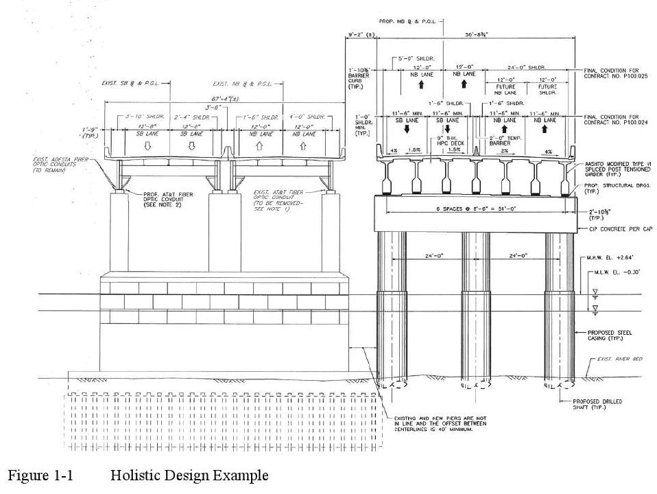
The manual also includes a comprehensive and holistic example of a bridge foundation designed with drilled shafts. The example, illustrated below in Figure 1-1, is an intermediate pier of a bridge across a river, with the bent supported by three columns. The new bridge replaces an adjacent existing structure founded on driven piles. The drilled shaft design is to consist of an individual shaft supporting each of the three columns. Details of the project requirements, subsurface information, and foundation design are presented in total in Appendix A of this manual and referenced throughout the manual where relevant aspects of design issues are discussed.
1.2 TYPES OF DEEP FOUNDATIONS
Drilled shaft foundations are broadly described as cast-in-place deep foundation elements constructed in a drilled hole that is stabilized to allow controlled placement of reinforcing and concrete. Several other types of deep foundations are employed in transportation works, as described below with distinctions from drilled shafts.
- Driven piles are prefabricated structural elements which are installed into the ground with a pile driving hammer. Driven piles have been used to support structures for thousands of years and in present times steel H, pipe, and prestressed concrete piles are commonly used for transportation structures. Guidelines for design and construction of driven pile foundations are provided by Hannigan et al in FHWA NHI-05-042 (2006). Driven piles are typically 12 to 36 inches in diameter or width and thus smaller in size than drilled shafts. Driven piles displace the soil into which they are driven and cannot penetrate hard materials or rock. In soft or caving soils there is no concern for stability of a hole.
- Micropiles are drilled piles which are typically less than 12 inches diameter and constructed using a high strength steel rod or pipe which is grouted into the bearing formation. Guidelines for design and construction of micropiles are provided by Armour et al in FHWA-SA-97-070 (2000). These piles can be drilled into even hard rock and achieve very high axial resistance for a very small structural member. Micropiles are favored in conditions where the small size is an advantage and where lightweight, mobile drilling equipment must be employed.
- Continuous flight auger piles and drilled displacement piles are drilled pile foundations which are typically 12 to 30 inches in diameter. These piles are distinguished from drilled shafts in that the pile is formed by screwing the continuous auger or displacement tool into the ground and then grouting or concreting through the hollow center of the auger; thus there is not an open hole at any time during the construction process. Guidelines for the design and construction of these types of piles are provided by Brown et al (2007).All of the types of piles described above are most often used in groups connected at the pile top with a reinforced concrete pilecap. Drilled shafts are distinguished from other types of piles in that drilled shafts are often substantially larger in size, frequently used as a single shaft support for a single column without a cap, and often installed into hard bearing strata to achieve very high load resistance in a single shaft. A description of drilled shafts and applications which may favor the use of drilled shaft foundations follows.
1.3 DRILLED SHAFT FOUNDATIONS – DESCRIPTION AND HISTORY
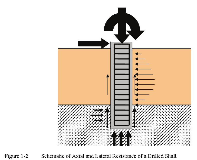 Drilled shaft foundations are formed by excavating a hole, typically 3 to 12 feet in diameter, inspecting the soil or rock into which the foundation is formed, and constructing a cast-in-place reinforced concrete foundation within the hole. The foundation as constructed supports axial forces through a combination of side shearing and end bearing resistance. The large diameter reinforced concrete member is also capable of providing substantial resistance to lateral and overturning forces as illustrated on Figure 1-2. Drilled shafts for transportation structures are fairly commonly used to depths of up to 200 ft in the U.S., but can extend to depths of as much as 300 ft or more.
Drilled shafts are also referred to by other names, including drilled piers, caissons, cast-in-drilled-hole piles (CIDH – Caltrans terminology), and bored piles (Europe). The common reference to these foundations as “caissons” reflects the history of development of drilled shaft foundations.
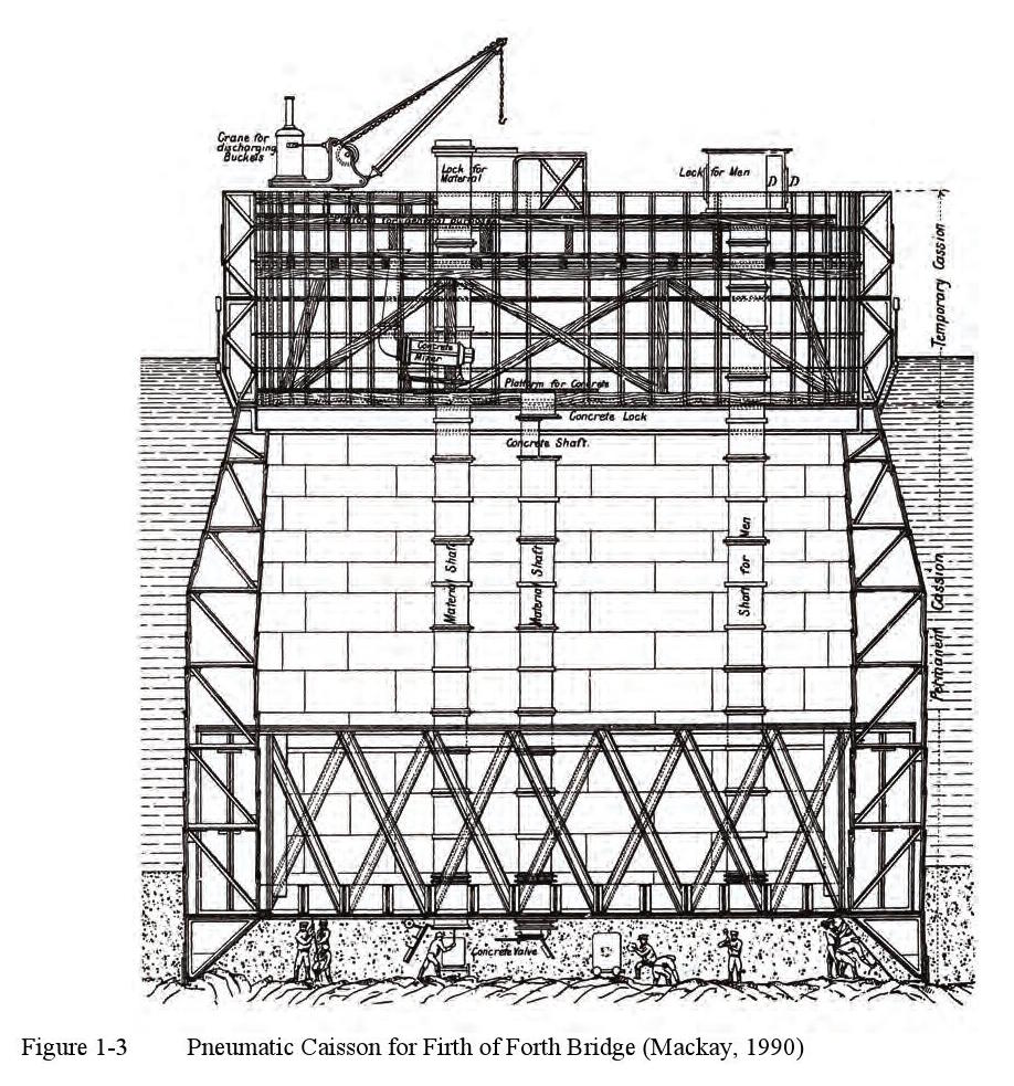
The term “caisson” is more accurately used to reference very large footings which are sunk into position by excavation through or beneath the caisson structure, and the use of drilled shafts evolved in many respects from caisson construction. Caisson construction has been used for hundreds of years, and was pioneered in the U.S. bridge construction in 1869 by James Eads in St. Louis and subsequently in the 1870’s by Roebling on the Brooklyn Bridge (McCullough, 1972). A diagram of caisson construction is shown on Figure 1-3 from one of the world’s most famous bridges, the Firth of Forth crossing in Scotland. These caissons were constructed as “pneumatic caissons” in which air pressure was maintained below the caisson as it sunk to prevent water inflow into the chamber below where workers excavated beneath the caisson cutting edge to sink the caisson to the required bearing stratum. Pneumatic caissons are rare today because of safety issues, but open well caissons are still occasionally used for bridges in deep water environments.
Open well caissons typically consist of a box open at both top and bottom, with dredge wells for excavating the soil through the caisson to sink it into place. Several large bridges have recently been constructed on large rectangular “open-well” caissons including the new Tacoma Narrows bridge and the Mississippi River crossing at Greenville, MS (Figure 1-4).
 Smaller, circular caissons or shafts were used to support building structures and some transportation structures in the early 1900’s in several large cities including Kansas City, Chicago, Boston, and New York. These early forms of drilled shafts were usually excavated by hand. The first known building supported on caissons of this type is the City Hall in Kansas City, which was constructed in 1890 (Hoffmann, 1966). Because of concern that timber piles might rot, the city building superintendent, S.E. Chamberlain designed the foundations to consist of 92 caissons, 41⁄2 ft diameter, placed to bear on limestone at a depth of around 50 ft. The excavation was supported by cylindrical sections of 3/16” boiler plate “to prevent the collapse of earth surrounding the excavation” (Chamberlain, 1891), and backfilled not with concrete but with vitrified brick laid in hydraulic cement. A drawing from the Kansas City Star newspaper is reproduced in Figure 1-5 below. Chamberlain’s description of this approach at the Annual Convention of the American Institute of Architects in Chicago in the fall of 1890 may have contributed to the adoption of this technique for several structures in that city soon afterward.
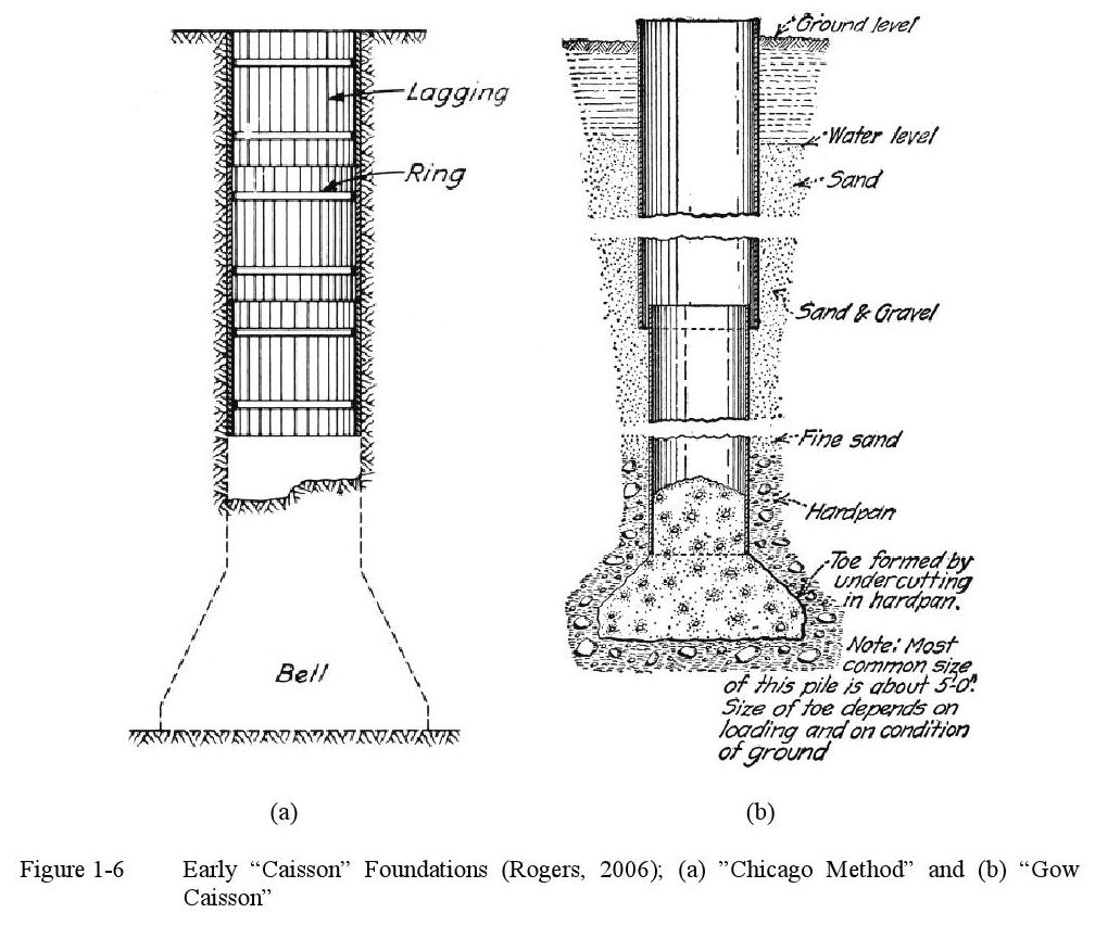
Several notable buildings in Chicago which had been founded on spread footings had suffered damaging settlement. The use of timber piles caused such heaving of the surrounding area that the owners of the Chicago Herald got a court injunction to stop construction of the pile foundations at the Chicago Stock Exchange building because of structural damage to their building (Rogers, 2006). The diagram at left of Figure 1-6 illustrates a foundation of the type designed by William Sooy Smith for one wall of the Chicago Stock Exchange building in 1893. The shafts were constructed as circular excavations with tongue and grooved timber lagging which was driven ahead of the excavation and braced with iron hoops. This method of excavation with timber lagging in a circular form became known as the “Chicago Method”. These types of foundations are not actually caissons in the true sense of the word, but the term stuck and is still used today even for modern drilled shaft construction.
The diagram at the right of Figure 1-6 illustrates a “Gow caisson” of the type pioneered by Col. Charles Gow of Boston who founded the Gow Construction Co. in 1899. The telescoping casing forms could be recovered during concrete placement. In the 1920’s, the Gow Company built and used a bucket-type auger machine which was electrically powered and mounted on the turntable frame of the crawler tractor of a crane (Greer and Gardner, 1986), thus promoting the development of machine-drilled shafts.
 Although there has been a significant evolution of the drilled shaft industry over the past 40 years to the type of construction and design which is prevalent today (2009), machine drilled shafts became more widespread during the 1930’s and became increasingly used during the building boom after World War II. The A.H. Beck Company began using drilled shafts in 1932 (photo in Figure 1-7) and, along with McKinney Drilling (founded 1937), were some of the pioneers of the drilled shaft industry in Texas. Augered uncased holes smaller than 30 inch diameter were common, and sometimes tools were employed to rapidly cut an underream or bell. In California, “bucket-auger” machines were more common, using a bottom dumping digging bucket to dig and lift soils rather than an auger.
Modern drilled shaft construction techniques are described in Chapters 4 through 9 of this manual and include equipment ranging from simple truck mounted equipment used to auger holes not much different from that used in the 1940’s to modern machines capable of drilling large, deep shafts into very hard materials (Figure 1-8). Workers do not generally enter the excavation and underwater concrete placement is commonly employed so that a dry excavation is not required. Techniques for testing to verify geotechnical strength and structural integrity are common so that drilled shafts can be used with a high degree of confidence in the reliability of the foundation.
The photo in Figure 1-9 shows construction of the main pylon foundation for a new cable-stayed Missouri River bridge in Kansas City, 108 years after the pioneering first use of drilled shafts for the City Hall. The equipment and construction methods have advanced far beyond the original concepts proposed in 1890 but the basic idea is the same: to support the structure on bedrock below weak soils using small, economically constructed “caisson” foundations. The history of drilled shafts is thus seen to have come full circle: the large caisson construction techniques used for bridges were adapted to construct small diameter “caissons” to support buildings which lead back to the use of large drilled shafts for bridges and other transportation structures.
The development of improved equipment, materials, and methods for design and testing have allowed the cost effective use of drilled shafts in a greater variety of applications and with greater reliability than was ever before possible. The following sections provide an overview of some applications of drilled shafts for transportation structures along with factors affecting the selection of drilled shafts as a deep foundation alternative.
1.4 SELECTION OF DRILLED SHAFTS
Drilled shafts can be installed in a variety of soil and rock profiles, and are most efficiently utilized where a strong bearing layer is present. When placed to bear within or on rock, extremely large axial resistance can be achieved in a foundation with a small footprint. The use of a single shaft support avoids the need for a pile cap with the attendant excavation and excavation support, a feature which can be important where new foundations are constructed near existing structures. Foundations over water can often be constructed through permanent casing, avoiding the need for a cofferdam. Drilled shafts can also be installed into hard, scour-resistant soil and rock formations to found below scourable soil in conditions where installation of driven piles might be impractical or impossible. Drilled shafts have enjoyed increased use for highway bridges in seismically active areas because of the flexural strength of a large diameter column of reinforced concrete. Drilled shafts may be used as foundations for other applications such as retaining walls, sound walls, signs, or high mast lighting where a simple support for overturning loads is the primary function of the foundation.
The following sections outline some applications for the use of drilled shaft foundations in transportation structures, followed by a discussion of the advantages and limitations of drilled shafts relative to alternative foundation types.
1.4.1 Applications
Drilled shaft foundations are logical foundation choices for a variety of transportation structures if the loading conditions and ground conditions are favorable. The following sections outline some of the circumstances where drilled shafts are often the foundation of choice for structural foundations.
1.4.1.1 Bridge Foundations
For foundations supporting bridge structures, conditions favorable to the use of drilled shafts include the following:
- Cohesive soils, especially with deep groundwater. For these type soil conditions, drilled shafts are easily constructed and can be very cost effective (Figure 1-10).
- Stratigraphy where a firm bearing stratum is present within 100 ft of the surface. Drilled shafts can provide large axial and lateral resistance when founded on or socketed into rock or other strong bearing strata.
- Construction of new foundations where a small footprint is desirable. For a widening project or an interchange with “flyover” ramps or other congested spaces, a single drilled shaft under a single column can avoid the large footprint that would be necessary with a group of piles. A single shaft can also avoid the cost of shoring and possibly dewatering that might be required for temporary excavations. Construction of drilled shafts can often be performed with minimal impact on nearby structures. Figure 1-11 illustrates some examples of these types of applications.
- Construction of foundations over water where drilled shafts may be used to avoid construction of a cofferdam. The photo in Figure 1-12 illustrates a two column pier under construction in a river with a single shaft supporting each column.
- Foundations with very high axial or lateral loads. The photo in Figure 1-13 shows construction of a 5-shaft group with a waterline footing for a bridge with large foundation loads in relatively deep water.
- Foundations with deep scour conditions where driven piles may be difficult to install. The photos in Figure 1-14 are from a bridge in Arizona. The original piles had been driven to refusal but subsequently one of the foundations had been lost due to scour.
- Construction of new foundations with restricted access or low overhead conditions. Often, high capacity drilled shaft foundations can be constructed in these circumstances with specialty equipment. Construction of new foundations for a replacement structure in advance of demolition of existing structures can be used to reduce the impact of construction on the traveling public. The photo in Figure 1-15 shows drilled shafts with low headroom.
-
 SPW911 Sheet Pile Design Software
Rated 5.00 out of 5$150.00 – $599.99Price range: $150.00 through $599.99
 -
 Sheet Pile Design (PDF Download)
Rated 5.00 out of 5$89.00
 -
 Pile Driving (PDF Download)
$89.00
-
 Marine Construction Volumes 1 & 2 (PDF Download)
$157.00
-
 Pile Driving (Book)
$89.00


