Chapter 13 – Sheet Piling Cofferdams
- Chapter 1 – Overview of Sheet Piling
- Chapter 2 – Structural Design of Sheet Pile Walls
- Chapter 3 – Overview of Soil Mechanics
- Chapter 6 – Dynamic Earth Pressures
- Chapter 9 – Design of Cantilevered and Anchored Walls Using Classical Methods
- Chapter 12 – Analysis and Design of Anchored Walls and Anchor Systems for Earthquake Loads
- Chapter 13 – Sheet Piling Cofferdams
For a complete version of this document click here.
13.1. General
A cofferdam is a retaining structure, usually temporary, which is utilized to keep water or earth out of an excavation site until the permanent works are constructed. Such struc- tures usually consist of vertical sheet piling walls forming a closed perimeter and braced internally or externally by a sys- tem of structural members or ties.
The bracing system consists of horizontal members called wales, which transfer loads from the sheet piling to compres- sion members called struts, or to external supports called tie backs or anchors.
The safe design of these temporary structures is important, since the safety of workmen or the protection of other struc- tures is almost always involved. The participation of wales and struts in the overall stability of cofferdams must be eval- uated much more closely than the support system of an anchored bulkhead. The sequence of construction regarding the excavation of soil or the pumping out of water from a cof- ferdam will affect the loads on all elements of the system. Maximum loading conditions may occur during the construc- tion phase, or during the placement of permanent work due to removal or relocation of bracing, rather than after the cof- ferdam is completed. In addition, pressures outside the wall may contribute to instability of the floor of the cofferdams that must be evaluated and accounted for in design planning.
Types of sheet pile cofferdams include the following:
• Water Cofferdams. Sheet piling “box” cofferdams are virtu- ally the only means for constructing permanent piers for bridges or other structures in water under dry conditions. Loads on these walls consist of unbalanced pressure from water and submerged earth.
• Land Sited Cofferdams and Trench Retainment Systems. Sheet pile cofferdams are constructed on land for any under- ground construction where workmen and adjacent structures must be protected against collapse of the excavation walls. If the area to be excavated is relatively small in area or the wall- to-wall distance is reasonable, internal cross bracing consist- ing of wales and struts is practical. If the area is large and the walls well apart, internal braces such as sloping raker struts, or external anchors behind the wall must be used. The values of earth pressure and its probable distribution against rigidly braced walls have been found to be at some variance with the pattern obtained by anchored, yielding walls.
13.2. Geotechnical Design of Sheet Pile Cofferdams
13.2.1. Lateral Pressure Distribution
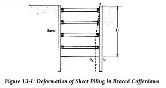 At the time the first row of struts is placed the excavation is not deep enough to have appreciably altered the original state of stress in the soil. The lateral pressure at the level of the first row of struts is, therefore, higher than the active pres- sure since no significant yielding of the soil mass has occurred. As the excavation continues to the level of the sec- ond set of struts, the rigidity of the first set prevents horizon- tal yielding of the soil near the surface. However, the external lateral pressure tends to rotate the sheeting about the upper support level so that a certain inward displacement of the sheeting will occur at the level of the second set of struts by the time these struts are in place. As the excavation continues, greater deflections occur at the lower struts mobilizing soil strength and producing an arching effect that reduces lateral pressures. At the completion of the excavation, the sheeting will have deformed to a position indicated by line ab1 in Figure 13-1. Thus, the resulting lateral pressure diagram will have the maximum values occurring in the upper portion of the wall.
In general, the deformation pattern resembles the arching, active condition and distribution of pressure is more likely to be parabolic rather than the triangular shape associated with the Rankine and Coulomb theories.
13.2.2. Pressure Distributions in Braced Cuts
The pressure distributions for braced cuts are different for sands and clays. Figure 13-2 shows these distributions. These pressure distributions are based on the following assump- tions:
• Apply to excavations greater than 20’ deep.
• An artificial loading diagram is used for determining strut loads.
• Water table is below the bottom of the excavation. If it is not, the distributions must be modified as discussed below.
It should be noted that there are other possible distribu- tions of pressure; however, this manual will use these in the sample problems. The basic solution methodology should be the same even with different distributions. These distribu- tions are explained in more detail in the following sections.
13.2.2.1. Braced Cuts in Sand
For braced cuts in dry or moist sand, a rectangular pressure distribution as proposed by Peck et al.142 and others may be considered. This distribution pattern is shown in Figure 13-2 (a), along with the value of pb.
If groundwater is present, and the pilings are tight and extend to an impermeable stratum, hydrostatic conditions will develop behind the wall. For water table at the backfill surface, use the submerged (buoyant) unit weight of soil in the equation of Figure 13-2 (a) and add the pressures from the unbalanced groundwater level. For a water table intermediate between the top and bottom of the cut, interpolate between the diagrams using the appropriate unit weight for the soil.
If seepage takes place behind the wall, the effective weight of the soil will be greater than the buoyant weight and may be conservatively assumed as the moist condition value. Water pressures along the back of the wall and in the backfill under seepage conditions can be reasonably estimated by flow net analysis.
13.2.2.2. Braced Cuts in Clay
For braced cuts in clay, Peck and others have suggested trapezoidal pressure distribution patterns. The use of these diagrams implies the designer has a good understanding of soil mechanics and is able to distinguish between the clays by sensitivity, cohesion values etc. The pressure distribution depends upon the stability number of the clay, which is given by Equation 4-26. Soft to medium clays (Nο > 6) have a pres- sure distribution as shown in Figure 13-2 (b) and stiffer clays (Nο < 4) as shown in Figure 13-2 (c).
The value of ‘m’ used in the determination of the ordinate for earth pressure applies to situations where the cut is under- lain by a deep deposit of soft clay. Its value can only be deter- mined by empirical means from measurements and perform- ance of an actual excavation. Experience thus far, reported by Peck from cases in Mexico City and in Oslo, Norway, leads to the conclusion that the value of ‘m’ is on the order of 0.4 for sensitive clays. For insensitive clays the value of ‘m’ may be taken as 1.0.
Water pressure is not added to the soil pressure since it is already included in the undrained strength considerations. Figure 13-2 (b) and Figure 13-2 (c) give maximum pressure values, which result in conservative designs for some struts. However, with the passage of time, creep effects cause the lat- eral earth pressure to increase appreciably. This phenomenon was studied in model tests by Kirkman,143 from which it was concluded that the design of more permanent cofferdams in clay should be based on earth pressures calculated according to the classical theories (Rankine, Coulomb or Log spiral) using a cohesion value of zero and a φ angle as determined by drained triaxial tests.
For a single layer of sand overlying a single layer of clay, Peck31 suggested substituting q and γ for 2c and g in the equa- tions for clay. These values are determined as follows:
Equation 13-1:
Where
• γs = saturated unit weight of sand
• Ks = hydrostatic pressure ratio for the sand layer (may be
taken as 1.0 for design purposes)
• Hs = thickness of the sand layer
• φ = angle of internal friction of the sand
• H = total depth of excavation
• qu = unconfined compressive strength of the clay
• γc = saturated unit weight of the clay
• n = coefficient of progressive failure. The value of n usually ranges from 0.5 to 1.0. This value varies with the creep characteristics of the clay, the length of time during which the excavation remains open, and the care exer- cised in construction. In Chicago clay, the value ranges between 0.75 and 1.0.
It should be recognized that Equation 13-1 and the dia- grams in Figure 13-2 (b) and Figure 13-2 (c) are based on stud- ies of 20- to 40-foot deep excavations above the water table with strut spacings of 6 to 20 feet. Before application to other conditions, including other depths or strut spacings and hydrostatic or seepage conditions special study may be required.
Surcharge loads from point, line or strip loads adjacent to the cofferdam must also be taken into account in final design.
13.2.2.4. Surcharge Loads Against Braced Cuts
A procedure for handling surcharge loads similar to that for bulkheads can be applied to braced cuts. A uniform sur- charge load of at least 300 psf is generally assumed to account for materials storage and light equipment near the wall. When converted to an equivalent height of soil, the pressure envelope is rectangular with an intensity of Ka.
Surcharge from point and line loads near the wall are quite intensive in the upper half of the excavation, putting more stress into the upper bracing sets than the lower. Equations based on Bousinesq’s work are an acceptable way of estimat- ing these loads.
13.2.3. Base Stability
The stability of the base of cuts must be checked. Unstable situations will require supplemental procedures beyond the simple shoring of the excavation walls. These procedures may…
-
 SPW911 Sheet Pile Design Software
Rated 5.00 out of 5$150.00 – $599.99Price range: $150.00 through $599.99
 -
 Sheet Pile Design (PDF Download)
Rated 5.00 out of 5$89.00
 -
 Pile Driving (PDF Download)
$89.00
-
 Marine Construction Volumes 1 & 2 (PDF Download)
$157.00
-
 Pile Driving (Book)
$89.00


