Chapter 3 – Seawalls
For a complete version of this document click here.
3.1 Types of Construction. (See Figures 1, 2, and 3.)
3.2 Selection Factors
3.2.1 Exposure. If location is subject to heavy wave attack (6 feet or greater significant wave height before breaking), select vertical wall, curved face, or rubble mound types. For locations subject to moderate wave attack (3 to 6 ft [.91 to 1.83 m]) significant wave height before breaking), use any type of seawall. For locations subject to light wave attack (4 ft [1.22 m] or less significant wave height before breaking), use any type of seawall or use a bulkhead.
3.2.2 Foundation Condition. For fair to good foundation conditions, any type of seawall is applicable provided that provision is made to prevent undermining due to scour. For poor foundation conditions, flexible types are applicable such as revetments and rubble mounds which can accommodate substantial settlement, pile supported designs such as stepped-face walls which are independent of settlement and soil strength, and lightweight, sloped constructions which minimize shear stress in the supporting soil. Where hard bottom (rock, hardpan) is located at reasonable depth, gravity structures, including curved face walls, should be considered. Seawalls supported on piles may be detailed to accommodate lateral movement as shown in Figures 4 and 5.
3.2.3 Beach Scour. Since a seawall is often located between the extreme high and extreme low tide marks or in shallow water, it is subject to scour from breaking waves. In deeper water, reflection from a vertical face wall may be expected to cause scour at the foot of the wall. Prevention of scour from breaking waves requires use of a toe blanket or a cutoff wall, which lets the scour occur but prevents undermining. The scoured volume normally fills again after the storm, but if scour, albeit temporary, is to be permitted, check stability of the wall under condition of maximum scour. The prevention of scour due to wave reflection (which implies water of sufficient depth at the face of the wall to prevent breaking of waves) can be facilitated by the use of rubble mound or stepped-face designs. For guidance in estimating depth of scour, refer to para. 3.4.1.
3.2.4 Overtopping. Vertical face and curved (concave) face walls tend to throw the reflected waves into the air where an onshore wind can carry a considerable quantity of water ashore. Wave run-up on paved slopes, such as concrete block revetment, also can result in a large quantity of water overtopping the wall. Where overtopping is a serious problem, rubble mound, stepped face, and similar energy-dissipating designs with or without a parapet wall at the top of the slope, or devices such as those shown in Figure 2, should be considered. A slight nose at the top of the wall helps to return the uprushing waves. A pronounced projection should be avoided.
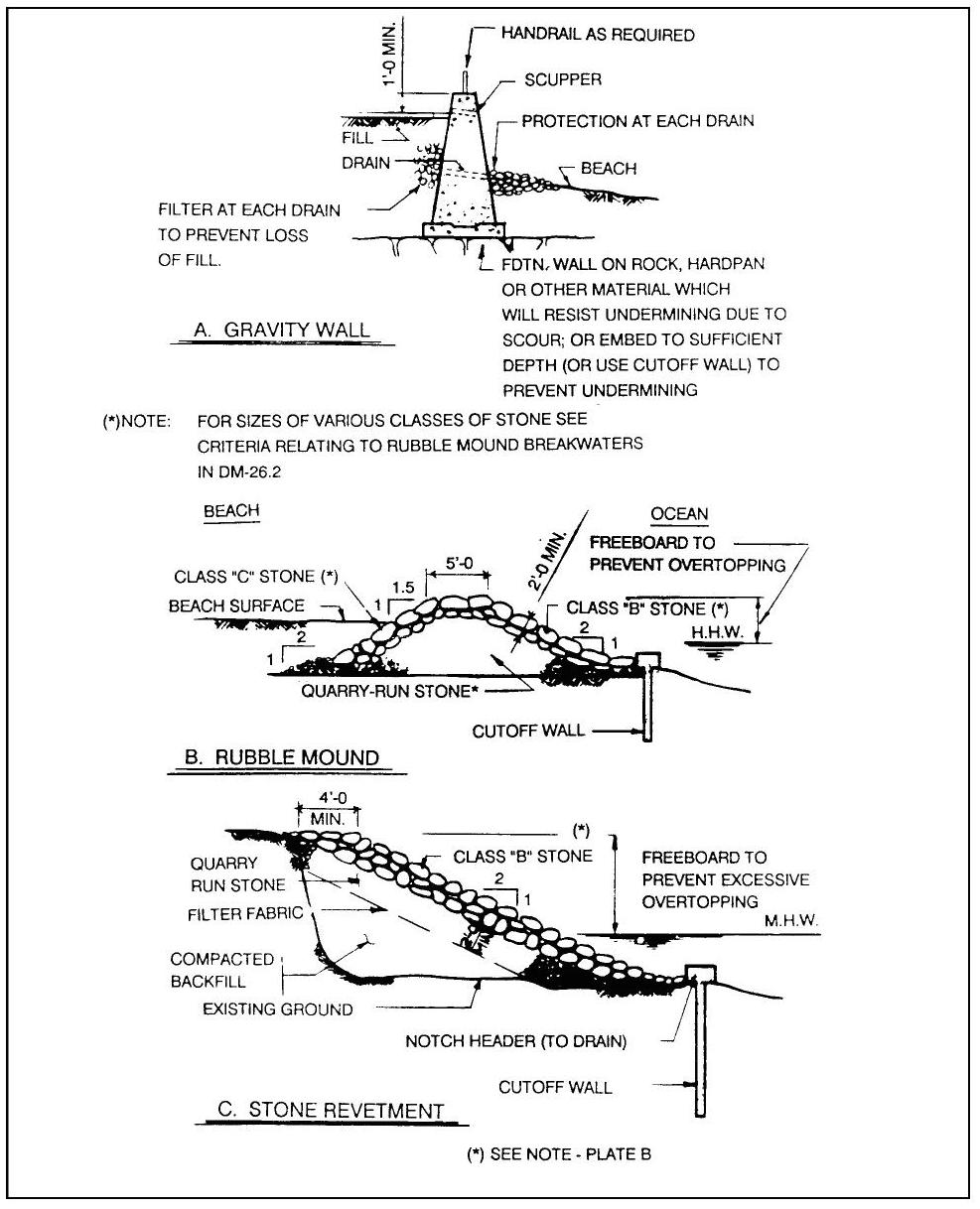
Types of Seawalls (Examples A thru C)
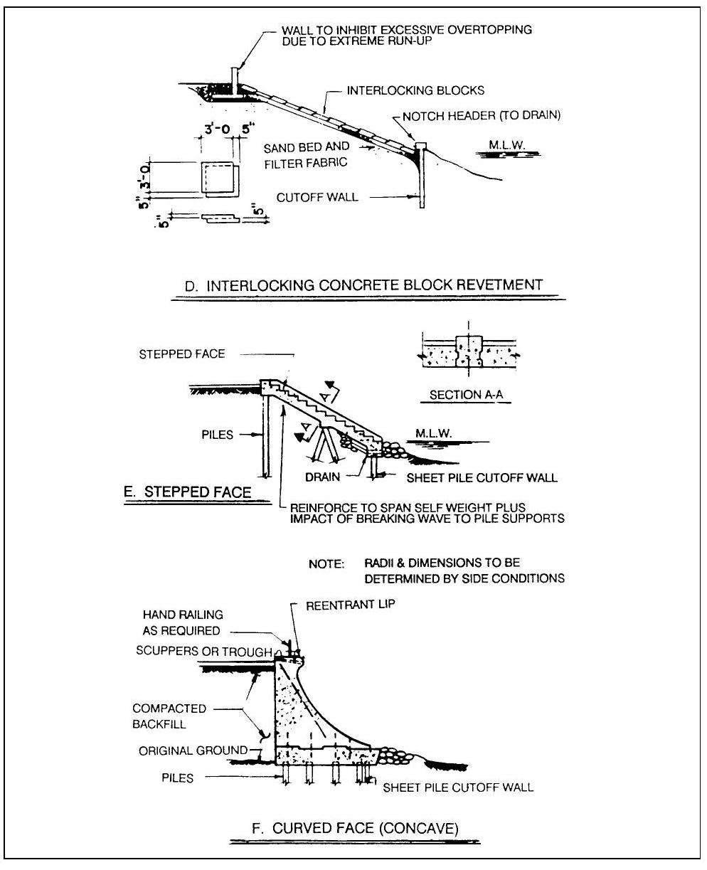
Types of Seawalls (Examples D thru F)

Types of Seawalls (Examples G thru I)
3.3 General Design
3.3.1 Forces to be Considered
a) Self-weight, weight of fill, and applied live load, in general.
b) Lateral earth pressure (refer to DM-7.01, Soil Mechanics, and DM-7.02, Foundations and Earth Structures).
c) Wave pressures and suctions.
d) Hydrostatic pressure due to tidal lag.
e) Surcharge.
f) Buoyancy.
3.3.2 Wave Pressures and Suctions
3.3.2.1 Height and Period of Incident Waves. (Refer to procedures in DM-26.2.)
3.3.2.2 Critical Depth for Breaking of Incident Waves. (Refer to DM-26.2.) Where the critical value of the ratio db:Ho (determined from the charts) approximates the actual value db:Ho at the wall, design the wall for pressures due to “breaking” waves. Where the actual depth-height ratio is less than the critical ratio, design the wall for pressures due to a “broken” wave. Where the actual depth-height ratio is greater than the critical value, the wall will be subject only to pressures due to “nonbreaking waves.”
3.3.2.3 Pressure Due to Breaking, Broken, and Nonbreaking Waves. (Refer to DM-26.2.)
3.3.2.4 Maximum Forces and Moments. Analyze several incident wave conditions (combinations of height and period) to determine the maximum forces and moments.
3.3.3 Tidal Lag. At high tide, the water level in the fill behind a bulkhead, seawall, or quaywall rises, but, because of the limited permeability of the fill, not as fast as the tide rises. Similarly, as the tide falls, the water level in the fill also falls, but not as fast. The lag in rise of the water level in the fill is of no concern as regards design of the wall. However, the lag in fall of the water level creates an unbalanced water pressure which must be resisted or accommodated by the structure. Therefore, where the wall stands seaward of the high-high water mark, design for tidal lag is as follows:
a) For permeable structures such as rubble mounds and for structures with permeable backfill (coefficient of permeability greater than one foot per minute), positive drainage of the backfill, and weep holes at or near the ground line at the front of the walls, assume zero tidal lag.
b) For structures backed by impermeable fill (coefficient of permeability of 10-3 ft/min or less), assume tidal lag equal to one-half the mean tidal range.
c) For structures backed by fill material having a permeability between 10-3 and one ft/min:
1) If the wall is of low permeability (sheet piling and few or no weep holes), assume tidal lag equal to one-half the mean tidal range.
2) If the wall is permeable (lagging, with spaces between the boards, gravel chimneys connected to weep holes or similar devices [see Figure 6]), treat the water load (saturation level above low water level) as a surcharge. The curves of Figure 6 assume semidiurnal tides. For diurnal tides, the effects of tidal lag will be less. See Figure 7 for a sample computation illustrating the use of the curves of Figure 6.
d) These allowances for tidal lag do not consider the effects of inundation of the backfill due to overtopping. If overtopping is anticipated and positive provisions have not been made to drain the overflow water away from the wall and to prevent its penetration into the backfill design for an assumed ground water level at the top of the wall. Allow 50 percent overstress (or reduce overall load factor to 1.2) for all loading combinations which include this assumption.
e) Add the tidal lag effect with low water condition on the outboard face.
3.3.4 Allowable Stresses. For Service Classification B, use allowable stresses given in MILHDBK-1002/2, Loads.
3.4 Design Details
3.4.1 Scour. Except in deep water, scour at the toe of a seawall during severe storms is inevitable. Provide a toe wall or toe armor to prevent undermining. The following may be used for guidance in detailing toe protection.
3.4.1.1 Width of Toe Armor. (See Figure 3, type H.)
3.4.1.2 Depth to Toe Wall. Assume scour depth below the natural seabed equal to the maximum unbroken wave height consistent with the depth of water at face of wall. For attack by broken waves, and for conditions of progressive shoreline erosion in general, refer to method in Section 5.28 of the Shore Protection Manual, U.S. Army Coastal Engineering Research Center. Design to ensure the stability of the wall in the scoured condition and provide excess toe armor or toe stone in rubble mounds of revetments to allow for the inevitable settlement and displacement during heavy wave attack.
3.4.2 Overtopping. Overtopping of a seawall in a severe storm is difficult to prevent. If substantive erosion of the upland due to the fall and wash of the water cannot be tolerated, the upland adjacent to, and a distance back of, the wall must be armored against erosion. Pavement close to the wall is required to resist the fall of the water thrown into the air by the impact of waves on the wall. If the upland slopes inshore, provisions must be made to collect and transport the overtopping water and to prevent erosion due to the run-off of said water. Plantings in lieu of pavement seldom work well. Use devices described in para. 3.2.4 to reduce overtopping…
-
 SPW911 Sheet Pile Design Software
Rated 5.00 out of 5$150.00 – $599.99Price range: $150.00 through $599.99
 -
 Sheet Pile Design (PDF Download)
Rated 5.00 out of 5$89.00
 -
 Pile Driving (PDF Download)
$89.00
-
 Marine Construction Volumes 1 & 2 (PDF Download)
$157.00
-
 Pile Driving (Book)
$89.00


