


Meeting the Power Grid Challenge: Quality Control for Transmission Foundations with TIP

by George Piscsalko, P.E. and Travis Coleman, P.E.
The recent growth in Artificial Intelligence (AI) data centers and Electric Vehicles (EV) has placed large demand on power grids around the world. In response to this increased power demand, there are many new electrical transmission projects underway or in the planning stages. Drilled shaft foundations are a popular choice for these foundations due to their ability to withstand large lateral loads that are expected from monopole and lattice tower structures due to wind and ice loads and line tension. The large diameter shafts are typically designed with a large steel content to connect the transmission tower to the foundation, to transmit large lateral loads through the foundation, as well as stiffeners to support the reinforcing cage and anchor system for lifting and placement into the excavation.

Many of the drilled shafts are cast below the groundwater tables where slurries are used to stabilize the surrounding soils. Shafts cast using slurries cannot be visually inspected. Even when slurries are used, unstable soils can collapse into the shaft, reducing or eliminating the expected concrete cover.
The large amount of steel required to withstand the large lateral loads along with bolt templates and stiffeners can obstruct the concrete flow to the area outside of the reinforcing cage resulting in a reduced concrete cover. Insufficient concrete cover can adversely affect the durability and performance of the foundation as the concrete cover helps to protect the reinforcing steel from being exposed to groundwater and caustic soils which can cause the steel to corrode and reduce the ability of the shaft to resist lateral loads. This requires much greater emphasis on quality control as any foundation failure could be catastrophic.
Non-Destructive Testing (NDT) can be used to assess the integrity of the shaft and the quality of concrete after casting to help ensure the as built shafts satisfy the design intent. Legacy NDT methods such as Low Strain Integrity (PIT) and Cross-Hole Sonic Logging (CSL) have proven to be insufficiently effective for evaluation of these large diameter shafts with significant reinforcing and anchor bolt steel content.
Thermal Integrity Profiling (TIP) is a proven, effective option in providing successful quality control for electrical transmission foundations. The TIP method utilizes the naturally occurring heat of hydration to assess the integrity of the drilled shafts. Temperature measurements are obtained from Thermal Wire® cables installed along the length of the reinforcing cage or outside the anchor bolt cage.

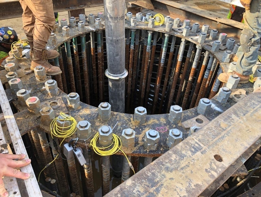
The thermal sensors are placed around the shaft with a frequency of one wire for every one foot (305 mm) of shaft diameter. The Thermal Wire cables have a digital temperature sensor located every one foot (305 mm) along the length of the wire as well. The thermal wires are cast into the shaft along with the reinforcing cage. Once the shaft is cast, data loggers are attached to each wire and data collection begins automatically and immediately. Each data logger (TAP-EDGE) reads temperature data from its attached wire and wirelessly transmits this data to a data logger (TAG) with an internal SIM card, which connects to the local cellular service and transmits data from all wires to the cloud (Figure 1).
Data is collected every 15 minutes per wire until the data loggers are disconnected from the wires, which should happen after the shaft reaches peak temperature. Once peak temperature is obtained, typically occurring within 24-48 hours of casting, all useful data has been captured and processed in the TIP analysis. Because the data is automatically collected and sent to the cloud, this typically minimizes or eliminates the need for site visits from the testing firm, reducing cost and scheduling risk for the contractor and owner. The speed of testing allows for quick correction to construction issues or unforeseen ground conditions which may cause defects in the shaft that would otherwise go undetected or not detected until after many shafts have been installed.
A locally abrupt reduction in temperature indicates an inclusion or location with a lower cement content/quality than the surrounding area. A locally abrupt increase in temperature indicates a bulge or area with higher cement content. Loss of concrete cover can also occur from eccentricities in the reinforcing cage. The TIP temperature data can be viewed so the Engineer can view diametrically opposite wires to determine if there is any cage shifting which may be causing a lack of desired concrete outside the reinforcing cage.
Utilizing the placed (not theoretical) volume in the shaft allows for the TIP-R program to calculate an effective radius over the shaft length. A 3-dimensional thermal image of the shaft can be obtained and indicate where the concrete cover is inadequate and will show areas where anomalies exist.
TIP has been used as the sole NDT method on electrical transmission line foundations for over ten years with great success. For a specific transmission line project in the Midwest United States, TIP testing was specified on all dead-end and angle shafts and 10% of tangent shafts. The project had shaft diameters ranging from 8 feet (2.4m) to 14 feet (4.3m) with lengths ranging from 30 feet (9.1m) to 46 feet (14m). One particular tangent shaft that was tested had very clear indications from the TIP test that there was a serious issue in the lower portion of the shaft. This shaft was 9 feet (2.7m) in diameter and 33 feet (10.1m) deep. The shaft had 9 thermal wire cables installed. The temperature vs. depth plot at peak temperature is shown in Figure 2.
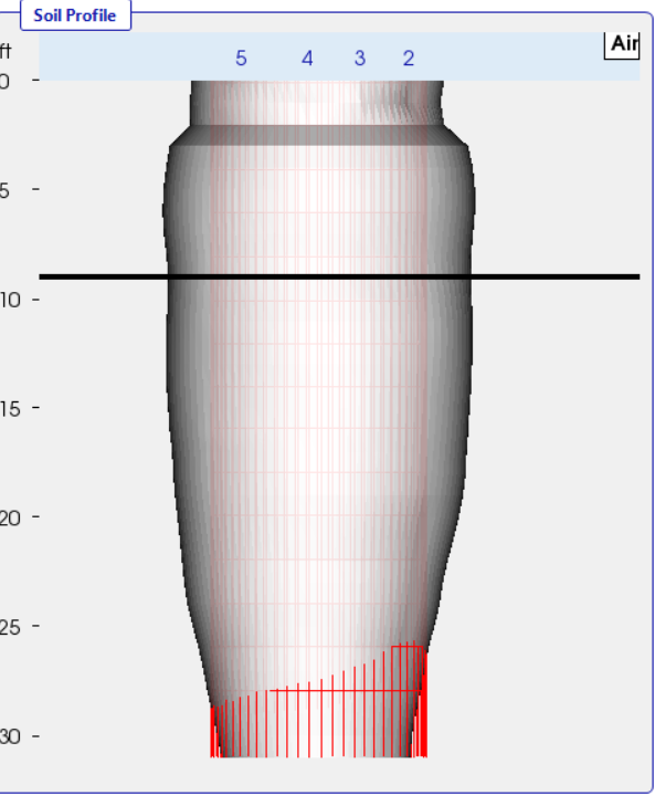
Once the volume data was included, an effective radius for the shaft can be determined (Figure 3) and the 3-dimensional image can be created (Figure 4). In reviewing the field logs, there was no indication of any quality issues related to this shaft with the placed concrete volume being 101% of the theoretical volume, but the TIP is clearly showing a shaft with a serious defect in the bottom portion below a depth of 16 feet (49m). The field report indicated the presence of seeping groundwater into the lower portion of the shaft prior to pouring but was pumped dry prior to concreting.
This temperature signature is associated with concrete placement through water, causing separation of the aggregate and cementitious materials. The shaft was cored (Figure 5) and the cores showed clearly that the bottom half of the shaft had inclusions and concrete with reduced quality and strength, with no material recovery in some of the cores near the shaft bottom. This particular shaft was a tangent shaft that was randomly tested and fortunately this occurred in one of the tested shafts, as opposed to the 90% of tangent shafts that went untested.

This shaft was abandoned and a replacement shaft installed. The contractor was quickly notified of this issue and was able to correct the construction techniques to eliminate further occurrences throughout the project, saving tremendous cost and potential catastrophe if the shaft had failed after line installation.
The TIP method overcomes the limitations of legacy methods as it does not have maximum length limitations, does not suffer from debonding of access tubes, is unaffected by the high concentration of steel in typical electrical transmission foundations, and can evaluate the entire length of the shaft, including the critical concrete cover. Additionally, the test is performed quickly to minimize any risk to the project schedule. The TIP method can identify significant anomalies in the shaft at a very early stage, allowing for near real time corrective actions to be undertaken.
Why is Thermal Integrity Profiling (TIP) used for drilled shaft foundations?
TIP assesses shaft integrity and concrete quality using heat of hydration, detecting defects that other NDT methods may miss.
How does TIP improve safety and efficiency in transmission tower foundations?
It identifies anomalies early, allowing rapid corrective actions and reducing risk of structural failure or schedule delays.