


How to Prevent Cofferdam Leaks: Design Considerations, Installation Best Practices, and More
View the complete article here.
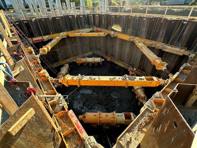
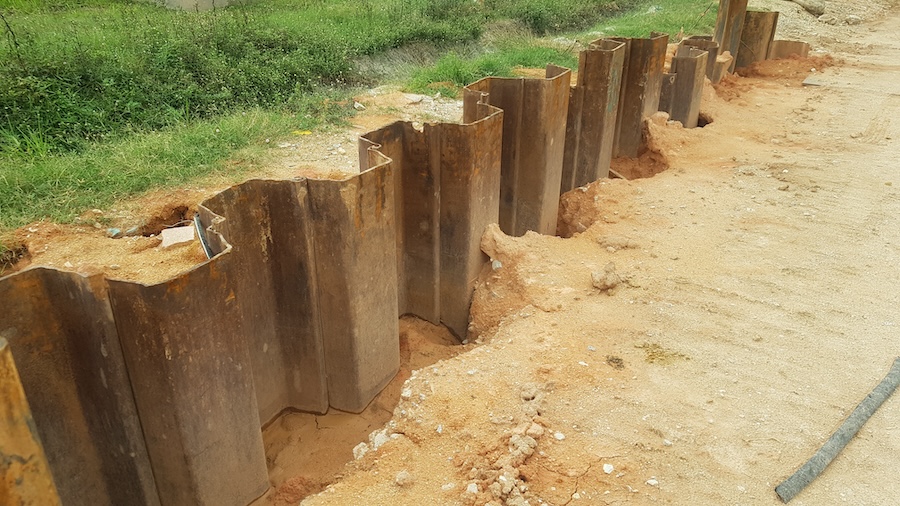
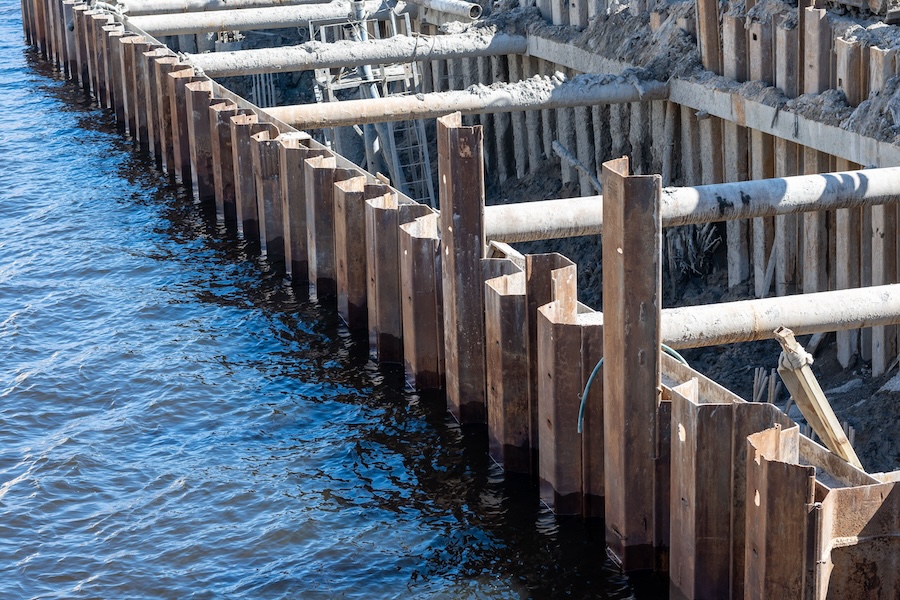
Cofferdams are critical temporary structures in construction—creating dry work environments for pile driving, bridge foundations, and underwater repairs by enclosing areas within bodies of water and pumping out the interior. However, leaks can compromise safety, delay projects, increase costs through excessive pumping, and risk structural failure due to uncontrolled water ingress. Common in sheet pile and cellular designs—leaks often stem from joint failures, poor installation, or inadequate sealing under hydrostatic pressure. With the construction industry facing tighter regulations and rising material costs, preventing leaks is paramount for efficiency and compliance. This guide draws on best practices from industry experts, including the U.S. Army Corps of Engineers (USACE) manuals EM 1110-2-2503 and EM 1110-2-1901, to help contractors implement proactive measures with detailed engineering insights.
Understanding Common Causes of Cofferdam Leaks
Identifying root causes is the first step in prevention. Leaks typically occur due to joint and interlock failures, such as gaps in sheet pile interlocks from misalignment, hard driving through dense strata, or wear in reused piles. Seepage through foundations is another major issue, where permeable soils allow underseepage, leading to uplift pressures and piping, which erodes soil particles. For instance, in coarse-grained soils like gravel and sand, undetected pervious seams can exacerbate this, potentially reducing foundation strength by up to 50% due to seepage forces.
Material degradation contributes as well, including corrosion, tears, or improper sealing at connections, often worsened by boulders in overburden or excessive jetting during installation. Hydrostatic and saturation issues arise from high water heads that saturate cell fills, relax interlocks, or cause overtopping during floods. Saturation can also result from waves splashing over the top, hydraulic dredge filling, or breaks in dewatering pump lines, increasing interlock stresses and leading to estimated inflows through interlocks of at least 0.025 gallons per minute per square foot of wall per foot of net head.
Finally, installation errors like out-of-plumb piles, inadequate bracing, or uneven driving can create gaps, particularly at corners. Structural failures, such as those in 90-degree welded tees, and scour from high-velocity flows further compound risks. By addressing these during planning, contractors can significantly reduce risks, as emphasized in USACE guidelines for evaluating full saturation effects unless controlled.
Installation Best Practices to Ensure Watertightness
Proper installation minimizes gaps and stresses. Drive progressively and plumb by completing each run of piling to grade, ensuring no pile leads adjacent ones by more than 5 feet to prevent splitting interlocks. Keep sections plumb and interlocked correctly before full driving, reversing hammer direction after each pass for accuracy.
Install bracing promptly, adding walers, struts, and bracing at specified elevations immediately after driving to limit deflection and maintain alignment.
Use tremie seals by pouring Grade T concrete tremie seals or subfootings to create a watertight base, cleaning corrugations fully for adhesion.
Handle connections carefully by driving connecting arcs after main cells, with initial sheets in place before filling, to avoid barrelling. Seal contacts with existing structures against sloped surfaces, using riveted or bolted connections with minimum 1/2-inch thick webs instead of welded tees.
Incorporate relief systems like relief wells or wellpoints in sand seams to dissipate hydrostatic pressure and control upward seepage, increasing underseepage by 20-40% but reducing uplift. Conduct diver inspections post-filling to verify interlocks, stopping dewatering if splits are found and potentially reflooding for repairs.
Design Considerations for Leak-Resistant Cofferdams
Effective design lays the foundation for leak prevention. Start by selecting the appropriate type and materials, such as hot-rolled steel sheet piles with ball-and-socket interlocks for superior watertightness in high-pressure environments. Vinyl sheets are suitable for less demanding sites, while double-walled cofferdams filled with earth or rock enhance stability and reduce leakage under pressure. For permanent or high-head structures, prefer new sheet piles in good condition to minimize interlock leakage.
Incorporate seepage controls by extending sheet pile penetration to two-thirds of cell height in pervious foundations, which lengthens drainage paths and reduces flow rates. Use flow net analysis to estimate seepage quantities and ensure exit gradients stay below 0.3-0.4 to prevent piping, with the critical hydraulic gradient (i_cr) calculated as (G_s – 1)/(1 + e), where G_s is specific gravity (typically 2.65 for soils) and e is void ratio, approximating 1 for clean sands. Factor of safety for exit gradients should be 4-5 for critical structures.
Add redundant features like berms on inboard or downstream sides to counter seepage forces and increase passive resistance. Design for free-draining granular fills with less than 5% passing the No. 200 sieve and 15% passing the No. 100 sieve to lower saturation levels and maintain interlock tension. Permeability can be estimated using Hazen’s formula: k = 100 D_10^2 (cm/sec), where D_10 is the effective grain size in cm.
Limit overburden risks by restricting driving through overburden to a maximum of 30 feet and excavating excess to avoid interlock damage. Avoid setting on bare rock without overburden support to preserve configuration. Coordinate hydraulic and geotechnical teams early to validate assumptions on saturation and permeability, using Darcy’s law (Q = k i A) for seepage quantity predictions, where Q is flow rate, k is permeability, i is hydraulic gradient, and A is cross-sectional area.
Sealing and Grouting Techniques
Advanced sealing reinforces integrity. Apply grout injections through curtain grouting—single or multiline—before, during, or after installation to seal foundations, reduce uplift, and cut dewatering costs. Select grout based on flow velocity and voids, drilling through overburden for precise application, with low-viscosity chemical grouts for fine contacts.
Install synthetic liners and membranes, such as liners or EPDM rubber rolls, for additional barriers, especially in high-seepage areas.
Use plugging methods by dropping fine cinders, clay, slag, or coal dust outside leaking joints to clog gaps. Plug handling holes on loaded sides to prevent fill loss.
For capping and weep holes, cap cells with 6-12 inches of lean concrete to avoid washout, and burn and maintain weep holes (1-inch diameter, at 5- to 6.5-foot vertical centers, every third to sixth sheet pile) on inboard sides for drainage, rodding them systematically. For “dirty” fills, use wellpoints or deep wells. For persistent issues, consult geotechnical services for custom sealing options, such as slurry trenches or diaphragm walls, as in the Wolf Creek Dam remedial project with a 278-ft-deep concrete cutoff.
Monitoring, Maintenance, and Dewatering Protocols
Ongoing vigilance sustains performance. Implement real-time monitoring using technology like piezometers, inclinometers, earth pressure cells, and strain gages to track water levels, structural integrity, and leaks continuously during dewatering and operation. Establish baselines post-installation and schedules for critical phases.
Perform regular inspections for alignment, sealing, and saturation, rodding weep holes systematically to ensure drainage.
Follow dewatering response by starting leak control immediately upon dewatering, noting that slower initial leakage aids quicker dry-out, with rates generally 5 feet per day after the first 15 feet. Install sumps or ditches for surface water control.
Prepare for floods by maintaining drainage during high floods to prevent interlock relaxation, capping if needed to block overtopping.
View the complete article here.
What causes cofferdam leaks and how can they be prevented?
Leaks often result from joint failures, underseepage, or poor installation, and can be prevented with proper design, bracing, sealing, and grout applications.
How should cofferdams be monitored during dewatering?
Use sensors and regular inspections to track water levels, interlock integrity, and seepage, addressing leaks immediately.