Chapter 4 – Footing Foundations
- Chapter 1 – Foundation Investigations
- Chapter 4 – Footing Foundations
- Chapter 5 – Pile Foundations
- Chapter 6 – Cast-In-Drilled-Hole Piles
- Chapter 7 – Driven Piles
- Chapter 8 – Static Pile Load Testing and Pile Dynamic Analysis
- Chapter 9 – Slurry Displacement Piles
- Chapter 11 – Ground Anchors & Soil Nails
- Chapter 12 – Cofferdams and Seal Courses
- Chapter 14 – Specialty Piles and Special Considerations for Pile Foundations
Foundations Manual by Caltrans
4-1 Introduction
Footing foundations, also known as spread, combined, or mat footings, transmit design loads into the underlying soil mass through direct contact with the soil immediately beneath the footing. In contrast, pile-supported foundations transmit design loads into the adjacent soil mass through pile friction, end bearing, or both. This chapter addresses footing foundations. Pile foundations are covered in Chapter 5, Pile Foundations-General.
Each individual footing foundation must be sized so that the maximum soil-bearing pressure does not exceed the allowable soil bearing capacity of the underlying soil mass. As the load-bearing capacity of most soils is relatively low (2 to 5 Tons per Square Foot (TSF)), the result is footing areas that can be large in relation to the cross section of the supported member. This is particularly true when the supported member is a bridge column.
In addition to bearing capacity considerations, footing settlement also must be considered and must not exceed tolerable limits established for differential and total settlement. Each footing foundation also must be structurally capable of spreading design loads laterally over the entire footing area.
Since the foundation is supported only by the supporting soil mass, the quality of the soil is extremely important. The contract specifications1 allow the Engineer to revise the footing foundation elevations to ensure that they are on quality material. Refer to Chapter 3, Contract Administration, for information on the responsibility of the Engineer as it applies to footing foundations.
4-2 Types
Footing foundations can be classified into two general categories:
- Footings that support a single structural member, frequently referred to as “spread footings.”
- Footings that support two or more structural members, referred to as “combined footings.”
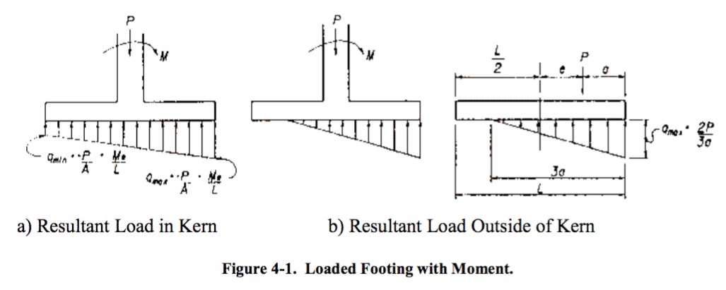
Typically, columns are located at the center of spread footings, whereas retaining walls are eccentrically located in relation to the centerline of a continuous footing. Locating a load away from the centroid (center) of the footing creates an eccentricity that changes the distribution of loads in the soil and may result in a bearing pressure that exceeds the allowable bearing capacity. These undesirable loading conditions increase the further the column is placed from the centroid or as the eccentricity increases. The worst of these cases is an edge-loaded footing where the edge of the column is placed at the edge of the footing. The major consideration for these footings is excessive settlement and/or footing rotation on the eccentrically loaded portion of the footing. The effect of column eccentricity on footing rotation and soil-bearing pressures is similar to a centrally loaded footing with a moment. This also will cause an unbalanced load transfer into the soil as shown in Figure 4-1.
In Figure 4-1, the moment (M) may come from a loading condition that needs to be transferred into the soil mass or may be the resultant of the length of the eccentricity multiplied by the load (P). The phrase “outside the kern” refers to a situation when the eccentricity is so great that there is no compression or, worse, there is tension on one side of the footing.
Problems resulting from eccentricities can be addressed by combining two or more columns onto a single footing. This usually is accomplished by one of two methods. In the first method, a single rectangular or trapezoidal footing supports two columns (combined footing). In the other method, a narrow concrete beam structurally connects two spread footings. This type is a cantilever or strap footing.
Combined footings generally are required when loading conditions (magnitude and location of load) are such that single-column footings create undesirable loading conditions, are impractical, or uneconomical. Combined footings also may be required when column spacing is such that the distance between footings is small or when columns are so numerous that footings cover most of the available foundation area. Generally, economics will determine whether these footings should be combined or remain as individual footings. A single footing that supports numerous columns and/or walls is referred to as a mat footing, and is commonly seen in building work.
Caltrans performed seismic retrofits of spread footings extensively throughout the 1990’s. Although this is not a separate category, it is important to understand that foundation work sometimes entails modifications of an existing structure. While the retrofit program is, for the most part, complete there still are structures that may need upgrades either for seismic concerns, scour, or bridge widening. Details of previous footing retrofit strategies are shown in Appendix C, Footing Foundations.
Footing foundations encountered in bridge construction almost always support a single structural member (column, pier, or wall) and invariably are referred to as spread footings. Although closely spaced columns do occur in multiple column bents, they are rarely supported on a combined footing. However, recent seismic and scour retrofit projects have incorporated designs that joined together the adjacent footings.
4-3 Bearing Capacity
The ultimate bearing capacity of a soil mass supporting a footing foundation is the maximum pressure that can be applied without causing shear failure or excessive settlement. Ultimate bearing capacity solutions are based primarily on the Theory of Plasticity; that is, the soil mass is assumed to be incompressible (does not deform) prior to shear failure. After failure, deformation of the soil mass occurs with no increase in shear (plastic flow).
The implication of the previous statements is that theoretical predictions can only be applied to soils that are homogeneous and incompressible. However, most soils are neither homogeneous nor incompressible. Consequently, known theoretical solutions used in bearing capacity analyses have been modified to provide for variations in soil characteristics. These modifications primarily are based on empirical data obtained through small and, more recently, large-scale testing.
The ultimate soil strength is referred to as Gross Ultimate Bearing Resistance (qn) in Load Resistance Factor Design (LRFD) and Ultimate Gross Bearing Capacity (qult) when working with Working Stress Design (WSD). Once qn and qult are calculated, the value is reduced by a factor of safety. The revised value is referred to as Allowable Bearing Capacity (qall).
4-3.1 Failure Modes
The mode of failure for soils with bearing capacity overloads is shear failure of the soil mass that supports the footing foundation. It will occur in one of three modes:
1. General shear. 2. Punching shear. 3. Local shear.
The Theory of Plasticity describes the general shear failure mode. The other two failure modes: punching and local shear, have no theoretical solutions.
A general shear failure is shown in Figure 4-2 and can be described as follows: The soil wedge immediately beneath the footing (an active Rankine zone acting as part of the footing) pushes Zone II laterally. This horizontal displacement of Zone II causes Zone III (a passive Rankine zone) to move upward.
General shear failure is a brittle failure and usually is sudden and catastrophic. Although ground surface bulging may be observed on both sides of the footing after failure, the failure usually occurs on one side of the footing. Two examples of this failure are:
- An isolated structure may tilt substantially or completely overturn.
- A footing restrained from rotation by the structure will see increased stresses in the footing and column portions of the structure, which may lead to excessive settlement or collapse.
-
 SPW911 Sheet Pile Design Software
Rated 5.00 out of 5$150.00 – $599.99
 -
 Sheet Pile Design (PDF Download)
Rated 5.00 out of 5$89.00
 -
 Pile Driving (PDF Download)
$89.00
-
 Marine Construction Volumes 1 & 2 (PDF Download)
$157.00
-
 Pile Driving (Book)
$89.00


