Chapter 2 – Structural Design of Sheet Pile Walls
- Chapter 1 – Overview of Sheet Piling
- Chapter 2 – Structural Design of Sheet Pile Walls
- Chapter 3 – Overview of Soil Mechanics
- Chapter 6 – Dynamic Earth Pressures
- Chapter 9 – Design of Cantilevered and Anchored Walls Using Classical Methods
- Chapter 12 – Analysis and Design of Anchored Walls and Anchor Systems for Earthquake Loads
- Chapter 13 – Sheet Piling Cofferdams
For a complete version of this document click here.
2.1. Materials Used in Sheet Piling
2.1.1. Grades Of Sheet Piling Steel
2.1.1.1. Basic Grade: ASTM A-328
The basic specification for steel sheet piling in the United States has been ASTM A-328 published by the American Society of Testing Materials. This grade has been satisfactory for most applications in that it provided a relatively high yield point for design and a high ultimate strength for drivability. The formulation is not well respected for weldability, although procedures for welding this grade have been published or are available from the manufacturers. The steel is not particularly tough and fractures originating at notches have been noted, particularly in cold environments. This steel has a minimum yield point of 39 ksi and a minimum tensile strength of 70 ksi.
2.1.1.2. Higher Strength Grade: ASTM A-572
Higher strength steels for structural applications are available for sheet piling such as the ASTM A-572 series. All strengths may not be available from every manufacturer, however Grade 50 is almost always offered. High strength grades find application (1) to substitute a lighter section of higher strength for a heavier section of regular strength, (2) to maintain safety factors against yield where it cannot be accomplished with section modulus. High strength grades can maintain some safety factor against yield where corrosion might reduce section properties. High strength steels, are generally more weldable than higher carbon grades.
ASTM A-572 Grade 50 has a minimum yield point of 50 ksi and a minimum tensile strength of 70 ksi. Safety factors for the high strength steels are similar to lower strength grades. It is now available as silicon killed, fine-grain formulation with greatly improved Charpy V-Notch impact properties. This steel might be considered for fracture critical applications, (for example, construction in arctic regions) and structures subject to impact. This is a premium priced formulation.
2.1.1.3. Corrosion Resisting Grade: ASTM A-690
ASTM-A-690 Grade was developed to recognize specially formulated steel for sheet and H-piles for use in salt-water applications. This grade has shown advantages over regular carbon steels for resisting corrosion in the salt-water splash zone that is an area of concern. The steel also provides a minimum yield point of 50 ksi and therefore can be designed along the lines of A-572 steels. In some cases weight can be reduced, thus providing a saving which will pay some of the additional cost of the grade. More discussion of this material is provided in 17.4.4.1.
2.1.1.4. Structural Factors of Safety for Steel Sheet Piling
Most steel sheet piling is still designed using allowable stress design methods; thus, a factor of safety is usually specified that reduces the allowable stress in the pile from the yield stress. The allowable stress is thus
Equation 2-1: σallow = Freduction σy
where
- σallow = Allowable Stress of the Material
- Freduction = Reduction factor of safety
- σy = Yield Stress of the Material, psi or kPa
With steel piling in pure bending (see below), there are two reduction factors used:
For static loads, for permanent works the reduction factor is generally 0.65, or the allowable stress is 65% of the yield stress. For the grades listed above:
ASTM A328: σallow = (0.65)(39) ≈ 25 ksi
ASTM A572, ASTM A690: σallow = (0.65)(50) ≈ 32.5 ksi
For earthquake loads, the reduction factor is generally (1.33)(0.65) ≈ 0.87, or the allowable stress is 87% of the yield stress. Using this increased value for earthquake loads presupposes a static analysis to insure that the static case is not in fact the governing case for a particular situation (see Example 19). For the grades listed above:
ASTM A328: σallow = (0.87)(39) ≈ 34 ksi
ASTM A572, ASTM A690: σallow = (0.87)(50) ≈ 43.5 ksi
2.1.2. Other materials
Aluminium used in sheet piling is generally the same as other extruded aluminum shapes. Material properties can be obtained from the manufacturers and is also discussed extensively in Pile Driving by Pile Buck. Also discussed more extensively in the same book is wood; greenheart wood, for example, has excellent material properties.
Vinyl and pultruded fiberglass piles are made of materials whose properties vary widely from manufacturer to manufacturer. Thus, it is critical in the specification of these sections to verify both the mechanical properties and the method in which these mechanical properties were obtained. It is also important to note that, with both of these materials, application of these material properties are subject many factors, such as creep (in the case of vinyl sections) and transverse bending and localised buckling (with both of these materials.)
2.2. Bending of Sheet Piling
2.2.1. Theory of Pure Bending of Sheeting
For the structural analysis of sheet piling, the primary object is to analyse failure due to excess bending moment and stresses. Most of the analysis of cantilever and anchored walls involve the computation of pure bending. For the case of pure bending, the maximum allowable bending moment is given by the equation
Equation 2-2: Mallow = Smin σ allow
where
- Mallow = Allowable bending moment
- Smin = Minimum Section Modulus
Both the allowable bending moment and the section modulus are specified as per lineal foot or meter of wall. The strength of sheet piling to resist bending is a combination of the shape of the section and the material out of which it is made. The allowable stress of the material is a function of the material itself.
2.2.2. Application of Bending to Specific Sheet Pile Sections
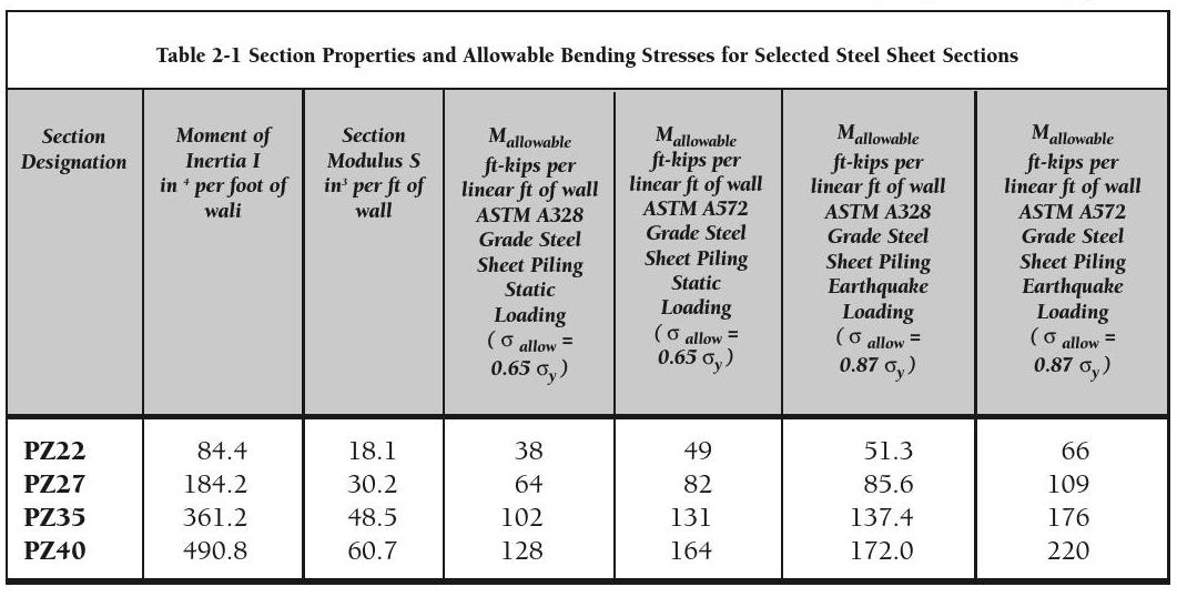
The century long development of sheet piling has led to a proliferation of sections of all kinds. These are constantly changing; a table of these is beyond the scope of this book, although they are available in both printed and online form from Pile Buck. For the purposes of the example problems in this book, however, we will use several commonly used sections that have been manufactured in steel for many years. These are shown in Table 2-1.
2.2.3. Combined Axial and Flexural Stresses
Additionally, sheet piling can experience axial loading as well from sources such as concrete pile caps at the top, axial forces due to the vertical component of an inclined anchor, and the friction of the soil. Especially with the pile caps, these can induce buckling in the sheet piling. This can be computed by modifying Equation 2-2 and solving for the maximum (or allowable) stress:
Equation 2-3:
σmax = Paxial + Mmax + Paxial (δmax + ep) < σ A allow axial Swall
Where
- Mmax = maximum moment of the sheeting
- Paxial = axial load on sheeting
- Aaxial = area of the sheeting subject to axial loads
- δmax = maximum deflection of the sheeting
- ep = eccentricity of the load from the centreline of the sheeting
This type of loading on sheet piles is especially important for HZ walls, and is demsonstrated in Example 24.
It is recommended that unless it can be shown that buckling of the piling is unlikely,
Equation 2-4: Mmax > Paxial ( δmax + ep ) 10
2.2.4. Section Modulus of U- Shaped Sheeting
As noted above, the section modulus is strictly a function of the physical shape of the material; however, with steel sheeting, Larssen and Z-shapes have been involved in a long running difference between European and American practice.
Larssen and other U-shaped piles remain popular in Europe and the Far East but were displaced in the United States by the Z-type profile. Why? At the heart of the problem is a difference in engineering philosophy.
As we said before, sheet pile walls are considered to act as a beam. For most shapes, the neutral axis will fall midway between the two outer faces of the sheeting, in a manner similar to H-beams. With a Larssen wall, the line of the interlocks falls on the neutral axis, whereas for a Z-wall it does not. Since the inception of the Larssen type pile, which interlocks along the neutral axis of the wall, there has been concern about the ability of the interlocks to transfer horizontal shear, without which the full section strength cannot be developed.
The European philosophy has been quite liberal toward this and one will find that the section modulus published for Larssen shapes is always based on full transfer or the “combined basis” with a reduction from this state left to the engineer.
Most American engineers have taken a more conservative approach and assumed that since this transfer cannot be counted upon without welding the joints, the section modulus of a wall with interlocks on the neutral axis should be based on the properties of the single pile rather than the combined pile system. This philosophy of course fostered the development of the Z-type shapes that interlock on the faces of the wall where horizontal shear is zero.
Realistically, there is general agreement that there is always some fixity attained in the interlocks, ranging from 100 percent downward. The American approach often resulted in a large safety factor many times and an uneconomical use of material. The European method may have produced some marginal safety factors at times but apparently few actual failures have been documented.
A series of shallow-depth arch sheet piles have been developed by the cold finishing industry. These sections, for the most part, interlock with their neighbours on one wall face, away from the neutral axis. The questions raised in the preceding paragraph do not apply to these shapes and the published section modulus may be used in a manner similar to the Z-shapes.
2.2.5. Transverse Bending Failure
Transverse bending is a relatively newly recognized mode of failure in sheet piling. Although it interacts with classical bending, it is a separate failure mode of its own.
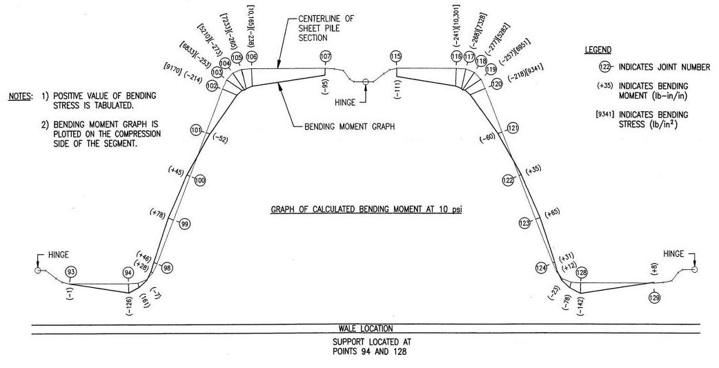
As we have seen, sheet-piling loads are primarily developed by lateral earth pressures, which in turn develop shears, moments, rotations and deflections in the beam. In addition to the flexural loading that is developed along the axis of the sheet pile, these pressures also act directly on the sheeting, producing transverse loading as shown in Figure 2-1. In essence, the lateral pressure is flattening the sheet; the plate bending at the corners is the resistance of the sheeting to this flattening. This bending is independent of classical flexure, but the combined stresses can exceed the limit of the material even when classical flexure predicts otherwise.
-
 SPW911 Sheet Pile Design Software
Rated 5.00 out of 5$150.00 – $599.99
 -
 Sheet Pile Design (PDF Download)
Rated 5.00 out of 5$89.00
 -
 Pile Driving (PDF Download)
$89.00
-
 Marine Construction Volumes 1 & 2 (PDF Download)
$157.00
-
 Pile Driving (Book)
$89.00


