Chapter 6 – Casings and Liners
- Chapter 1 – Selection and Use of Drilled Shaft Foundations for Transportation Structures
- Chapter 2 – Site Characterization
- Chapter 4 – General Construction Methods
- Chapter 5 – Tools and Equipment
- Chapter 6 – Casings and Liners
- Chapter 8 – Rebar Cages
- Chapter 9 – Placement and Design of Concrete For Drilled Shafts
From Drilled Shafts: Construction Procedures and LRFD Design Methods by FHWA
Casings and liners play an important role in the construction of drilled shafts, and special attention must be given to their selection and use. Except for surface casing or guides, the casings and liners that are described in this chapter are used for support of the drilled shaft excavation, and/or may serve as a structural element of the completed drilled shaft. Casings and liners are used in conjunction with rotary drilling or other techniques described in Chapters 4 and 5 for constructing drilled shafts.
Casings are tubes that are relatively strong, usually made of steel, and joined, if necessary, by welding or, in some cases, bolting. Casings may also have special joints that allow torque and axial load to be transferred to the tip, such as those that are used with full depth casing machines.
Liners, on the other hand, are light in weight and become a permanent part of the foundation. Liners are often made of corrugated sheet metal pipe (CMP), but also may be made of plastic or pressed fibers (e.g., SonotubeTM). While their use is much less frequent than that of casings, liners can become important in some situations.
6.1 TEMPORARY CASING
Temporary casing is used to stabilize the drilled shaft excavation and then removed after or during placement of fluid concrete. Contractors like to emphasize the fact that the casing that is used temporarily in the drilling operation is essentially a tool, so it is sometimes termed “temporary tool casing.” This temporary casing is used to retain the sides of the borehole only long enough for the fluid concrete to be placed. The temporary casing remains in place until the concrete has been placed to a level sufficient to withstand ground and groundwater pressures. The casing is removed after the concrete is placed. Additional concrete is placed as the casing is being pulled to maintain the pressure balance. Thereafter, the fluid pressure of the concrete is relied upon to provide borehole stability. The use of temporary casing has been described briefly in Chapter 4.
When approved by the engineer, temporary casing used solely for support of the drilled shaft excavation may be left in place. In such cases, the engineer must assess the influence of the casing on the axial and lateral resistance of the completed drilled shaft.
Temporary casing must be cleaned thoroughly after each use to have low shearing resistance to the movement of fluid concrete. Casing with rough interior surface will increase the shearing resistance between the casing and the column of fluid concrete placed inside the casing. As the casing is lifted the drag on the column of concrete may cause the concrete to be lifted, creating a neck or a void in the concrete. The casing should be free of soil, lubricants and other deleterious material.
6.1.1 Types and Dimensions
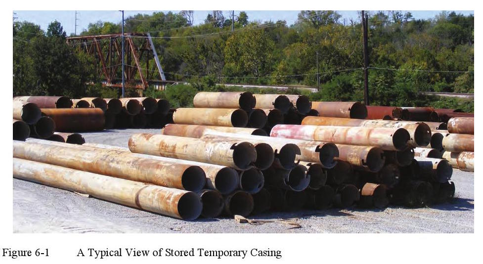
Most drilling contractors will maintain a large supply of temporary casing of various diameters and lengths in their construction yards. A typical view of stored temporary casing is shown in Figure 6-1. Casing from the stockpile may be welded or cut to match the requirements of a particular project.
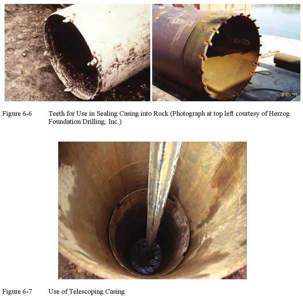
Temporary casing must sometimes be seated into an impervious formation such as rock if the excavation is to be advanced below the casing in the dry. In such a circumstance, it will normally be necessary to use the casing as a tool, with twisting or driving forces applied through the casing. The end of the casing may be equipped with cutting teeth or additional thickness in order to facilitate installation.
ADSC: The I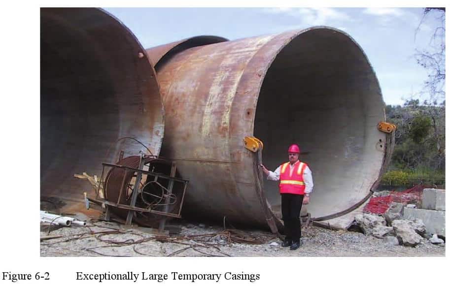 nternational Association of Foundation Drilling, has adopted the outside diameter of casing as a standard and uses traditional units [e.g. 36-in. O.D.] because used pipe in O.D. sizes is available at much lower cost than specially rolled pipe with specified I.D. (ADSC, 1995). Specially ordered pipe of a specific size can be ordered, but at higher cost and with the added requirement of lead time for fabrication. Ordinarily, O.D. sizes are available in 6-inch increments 18 in., 24 in., 30 in., and so on up to 120 in. Larger sizes as shown in Figure 6-2 typically require special order and fabrication.
If temporary casing size is not specified, most contractors will usually employ a casing that has an O.D. that is 6 inches larger than the specified drilled shaft diameter below the casing to allow for the passage of a drilling tool of proper diameter during final excavation of the borehole. A drilling tool with a diameter equal to the specified shaft diameter below the casing will usually be used. If there is a boulder field or if the contractor otherwise decides to use telescoping casing, the first casing that is set may have an O.D. that is more than 6 inches larger than the specified shaft diameter.
The contractor is usually responsible for selecting a casing with sufficient strength to resist the pressures imposed by the soil or rock and internal and external fluids. Most steel casing has a wall thickness of at least 0.325 inches, and casings larger than 48 inch O.D. tend to have greater wall thicknesses. Installation with vibratory or impact hammers may require greater wall thickness than would be used for casing installed in an oversized hole. Most contractors rely on experience in the selection of casing wall thickness. However, if workers are required to enter an excavation, the temporary or permanent casing should be designed to have an appropriate factor of safety against collapse.
 The computation of the allowable lateral pressure that can be sustained by a given casing is a complex problem, and methods for such computations are beyond the scope of this publication. The problem is generally one of assuring that buckling of the casing does not occur due to the external soil and water pressures. Factors to be considered are: diameter, wall thickness, out-of roundness, corrosion, minor defects, combined stresses, microseismic events, instability of soil on slopes and other sources of nonuniform lateral pressure, and lateral pressure that increases with depth.
Semi-rigid liners can be used for liners or temporary casing that may be left in place. They can consist of corrugated sheet metal, plain sheet metal, or pressed fiber. Plastic tubes or tubes of other material can also be used. These liners are most often used for surface casing where it is desirable to restrain unstable surface soil that could collapse into the fluid concrete, creating structural defects. For example, corrugated sheet metal is often used for this purpose when the concrete cutoff elevation is below working grade. Occasionally, rigid liners, such as sections of precast concrete pipe, are also used effectively for this purpose.
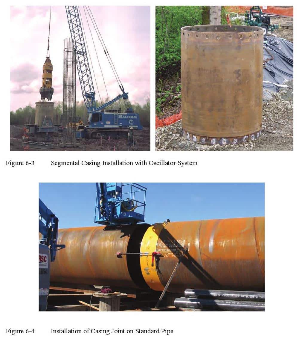
Rotators and/or oscillators with segmental casing (Figure 6-3) are increasingly being used to advance large diameter, deep drilled shafts. The casing penetration is advanced ahead of the excavation thus providing support for the excavation and eliminating the need for slurry for side wall stability. Slurry or water may still be necessary to prevent base heave. Soil can be removed within the casing with clam, hammer-grab, or rotary tools. The casing is typically high strength steel, often double-wall, with flush fitting joints between segments. Details of the connection between casing segments allow for the transmission of torque, compression, and tension between casing sections. This allows large torque (in either direction), compression, and lifting forces applied by equipment at the surface to be transmitted from the top section of casing to the bottom section of casing. Although the double walled casing shown in Figure 6-3 is most often used, it is possible to weld the casing joints to standard pipe as illustrated in Figure 6-4. In this case the casing joint will protrude into the interior of the casing.
6.1.2 Installation and Extraction of Temporary Casing
As described in general in Chapter 4, temporary casing is often placed into an oversized drilled hole and then seated into the underlying formation to provide a stable environment, but temporary casing can also be advanced ahead of the excavation. Methods for installation and extraction of temporary casing are described below.
6.1.2.1 Casing Seated Through Drilled Hole
Temporary casing can be placed through a pre-drilled hole to seat the casing into an underlying formation of more stable material. The pre-formed hole may be constructed using the wet method with drilling slurry, or may sometimes be advanced without a drilling fluid if the soil will stand for a short period and the seepage into the hole is relatively small. The latter is often the case where the shaft can be drilled relatively quickly through a residual soil to rock, and the more time-consuming rock excavation is facilitated by having a temporary casing to prevent cave-ins of the overlying soil. If the shallow strata are water-bearing sands, it may be necessary to drill the starter hole with slurry to prevent caving. In some instances, contractors may use polymer slurry just to help “lubricate” the casing and make it easier to remove.
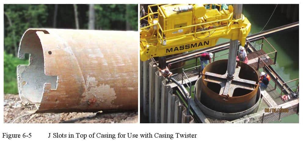
The excavation below the casing may be advanced as a dry hole if the casing is seated with a watertight seal into a relatively impermeable underlying formation of clay, chalk or rock. In order to seat the casing, a “twister bar” attachment to the kelly bar may be used to allow the drill rig to apply torque and crowd to the casing and advance it into the underlying soil or rock. Figure 6-5 illustrates casings with J-slots cut into the top to allow a casing twister to be used. In order to help the casing to cut into the underlying formation, the end of the casing is usually equipped with cutting teeth as shown in Figure 6-6. Various types of cutting teeth may be used, depending upon the type of material into which the casing is advanced; pointed rock teeth or even welded-on carbide chips may be used.
A good seal of casing into underlying rock can be very difficult if the rock surface is steeply sloping or highly irregular, or if the rock contains seams or joints that allow water inflow below the casing. An irregular hard surface will make the casing tend to deflect off alignment, break cutting teeth, and possibly bend the casing.
As described in Chapter 4, some contractors sometimes prefer to make deep excavations using more than one piece of casing with the “telescoping casing” process (Figure 6-7). This process has the economic advantage that smaller cranes and ancillary equipment can be used to install and remove telescoping casing than would be required with a single piece of casing. A borehole with a diameter considerably larger than that specified is made at the surface, and a section of casing is inserted. A second borehole is excavated below that section of casing, which is then supported with another section of casing of smaller diameter. This process may proceed through three or more progressively smaller casings, with the I.D.
(O.D- if excavating does not proceed below casing) of the lowest casing being equal to or greater than the specified diameter of the drilled shaft. The O.D. of a lower section of such “telescoping casing” is typically at least 6 inches smaller than the O.D. of the section above it, although larger differential diameters may be used when necessary. This procedure is most often used for drilled shafts that are bearing on or socketed into rock and where no skin friction is considered in the soils or rock that is cased. Care must be taken by the contractor that the process of removing the smaller section(s) of casing does not disturb the larger section(s) of casing still in place, or deposit water, slurry or debris behind casings still in place, thereby contaminating the fluid concrete. Telescoping casing may also be used to case through boulder fields where some boulders are removed and the casing is screwed ahead to refusal. The smaller inner casing is advanced through the first casing which retains the zone where the larger boulders were removed. The placement of concrete within a hole stabilized using telescoping casing is described in Chapter 9.
6.1.2.2 Casing Advanced Ahead of Excavation
The contractor may choose to advance the casing ahead of the excavation in cases where the hole will not stand open for short periods or where slurry drilling techniques are considered less attractive from a cost or performance standpoint. There are two primary methods used to advance casing ahead of the excavation. The contractor may drive the casing in advance using a vibratory hammer, or using oscillator/rotator equipment.
6.1.2.2.1 Vibro-Driven Casing
In the case of the driven casing, a vibratory hammer is almost always used for temporary casing; an impact hammer may be used to install permanent casing, but temporary casing will require a vibratory hammer for extraction since casing installed with an impact hammer may be impossible to remove. In principal, jetting could be utilized as an aid to installation, but jetting around the casing would not be advised during extraction due to the potential for jet water to adversely affect the fluid concrete.
In planning the construction of drilled shafts in congested areas, it should be noted that the use of vibratory installation of casing can cause significant vibrations that can affect nearby structures, or cause settlement in loose sands (which can affect nearby structures). The attenuation of vibrations with distance away from the source is affected by the size of the hammer and casing, the operating frequency of the hammer, the soil and rock properties, the localized stratigraphy, groundwater, and other factors that are likely site-specific. In most cases, vibrations from casing installation are extremely small at distances of 50 to 70 ft from the source. In cases where sensitive structures may be present nearby, a program of vibration monitoring should be included in the installation plan. Vibration monitoring can help avoid potential damage and can also provide documentation as protection against lawsuits or claims of damage caused by vibratory installation of casing. Monitoring during construction of the technique and test shaft installations can provide valuable measurements of vibrations at various radial distances from the source before moving the work into production locations. A useful reference on this subject is “Construction Vibrations” (Dowding, 2000).
Installation of the casing using a vibratory hammer is most effective in sandy soil deposits, and to penetrate through sandy soils into a clay or marl stratum below. The hammer clamps to the top of the casing (Figure 6-8), which is often reinforced at the end with an extra thickness to aid in resisting the transmitted forces. The vibration of the casing often causes temporary liquefaction of a thin zone of soil immediately adjacent to the casing wall so that penetration is achieved only with the weight of the casing plus the hammer. This technique is particularly effective in sandy soils with shallow groundwater. Penetration of an underlying hard layer such as hard rock may be difficult or impossible with a vibro- driven casing. Attempts to twist the casing with the drill rig to seat into rock are likely to be ineffective because of the side resistance of the soil against the casing after removal of the vibration.
In general, a vibratory hammer is used to place the entire length of temporary casing into the soil before excavation of soil inside the casing. However, to facilitate penetration through particularly dense soils, the casing can be installed by an alternating sequence of driving the casing and drilling to remove the soil plug within the casing. In this case, it would typically be necessary to install the casing in sections, with the sections joined by welding.
Removal of the casing with the vibratory hammer must be accomplished while the concrete is still fluid. During extraction, the hammer is attached and powered, and then typically used to drive the casing downward a few inches using the weight of the casing and hammer to break the casing free of the soil.
Once the casing is moved, the crane pulls the casing upward to remove it and leave the fluid concrete filled hole behind.
6.1.2.2.2 Oscillator/Rotator Method
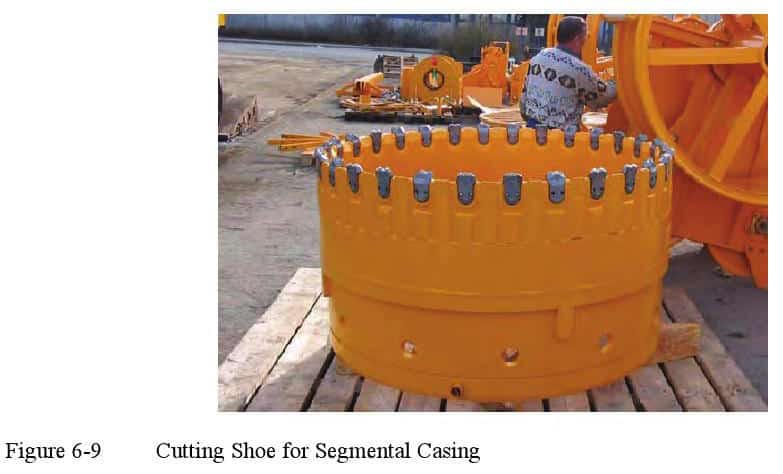
Installation of temporary casing ahead of the excavation may be accomplished with a drill using the special casing and tools illustrated previously in Figures 6-3 and 6-4. A general description of the machines used for the oscillator/rotator method of construction was provided in Chapter 5. The oscillator or rotator clamps onto the casing with powerful hydraulic jaws and uses hydraulic pistons to twist the casing and push it downward, reacting against a large drilling machine or temporary frame. The casing is therefore used in the same manner as a coring tool to advance into the soil or rock. In order to advance the casing and overcome the soil side shearing resistance to twisting, it is necessary that the casing have cutting teeth slightly larger than the outside dimension of the casing. The bottom section of casing is fitted with a cutting shoe to promote penetration (Figure 6-9) by cutting a slightly oversized hole and relieving the stress against the sides of the casing. The soil on the interior of the casing is excavated simultaneously as the casing is installed to remove the resistance of this portion of the soil.
 Installation of temporary casing ahead of the excavation may be accomplished with a drill using the special casing and tools illustrated previously in Figures 6-3 and 6-4. A general description of the machines used for the oscillator/rotator method of construction was provided in Chapter 5. The oscillator or rotator clamps onto the casing with powerful hydraulic jaws and uses hydraulic pistons to twist the casing and push it downward, reacting against a large drilling machine or temporary frame. The casing is therefore used in the same manner as a coring tool to advance into the soil or rock. In order to advance the casing and overcome the soil side shearing resistance to twisting, it is necessary that the casing have cutting teeth slightly larger than the outside dimension of the casing. The bottom section of casing is fitted with a cutting shoe to promote penetration (Figure 6-9) by cutting a slightly oversized hole and relieving the stress against the sides of the casing. The soil on the interior of the casing is excavated simultaneously as the casing is installed to remove the resistance of this portion of the soil.
During installation of the casing, it is essential that a plug of soil remain inside the casing (typically about one shaft diameter in thickness) so that the bottom of the excavation does not become unstable during installation. In water-bearing soils, the head of water inside of the casing must also be maintained so that bottom heave does not occur. It is possible to use slurry inside the casing to maintain stability, but the need for slurry is usually avoided by maintaining a soil plug. It is necessary to maintain stability during installation because heave of soil into the casing would cause loosening of the ground around the excavation with adverse effects on side shear and possible subsidence around the shaft.
At completion of the excavation, the soil plug may be removed to the base of the casing (or below) if the casing is extended into a rock or stable formation or if a slurry head is used to maintain stability. If the hole terminates in water-bearing soil with only a water head for stability, it may be necessary that the casing extend below the base of the final excavation to avoid instability at the base. However, this procedure may result in an annular zone of loosened soil at the base of the drilled shaft excavation.
The thicker casing (typically about 2 to 2.5 inches) used with this method of construction is a consideration in selection of the cover and the spacers on the reinforcement cage. If a single wall pipe is used with the casing joints as shown in Figure 6-4, the joints will protrude inside the casing because the joint is typically thicker than the pipe. In such a case, the reinforcing cage will need to be fabricated and placed carefully so that nothing hangs on the casing joints during installation of the cage and/or extraction of the casing during concrete placement.
To avoid potential torsional deformation of reinforcement, the casing is typically oscillated back and forth during extraction, even if a continuous rotation was used during installation. The casing is typically extracted simultaneously as concrete is placed into the excavation, and concrete head above the tip of the casing must be maintained so that a positive concrete pressure is provided against the hole. If exterior groundwater pressure is present, the head of concrete and water inside the casing must exceed the exterior water pressure in order to prevent inflow of water and contamination of the concrete. It is also essential that the concrete remain fluid so that the oscillation of the casing does not transfer twisting forces into the reinforcing cage and cause distortion.
6.1.4 Removing Casing after Concrete Sets
Drilled shafts installed through a body of water typically use a permanent casing that serves as a form until the concrete sets, and then is left permanently in place. It is often specified to remove portions of otherwise permanent casing that is exposed above the ground surface or above the surface of a body of water following completion of the drilled shaft installation and after the concrete has reached sufficient strength. In such cases, typically only a short section of casing would need to be removed. The removal would typically be accomplished by torch cutting the steel into sections, taking care to avoid damaging the underlying concrete surface, and detaching the individual sections from the surface of the concrete. However, temporary casings have occasionally been used for such applications, including various types of removable forms attached to the top of the permanent casing. There have been numerous reports of difficulties with the use of temporary casing over water.
An example of a removable casing is shown in Figure 6-12; this photo is taken from the I-95 Fuller Warren Bridge over the St. Johns River in Jacksonville, Florida. For this project, the removable casing was fabricated with a split seam that extended the entire length of the casing and was joined by a mechanical pin arrangement that kept the joint closed during casing installation and concrete placement, and expanded the joint to facilitate removal of the casing after the concrete achieved the required strength. A rubber gasket was placed in the joint in an effort to make the joint water tight. In this example, the 72- inch diameter casings were advanced with a vibratory hammer through soft river bottom deposits either to a stiff silty clay layer or to limestone. After the drilled shaft concrete set, the pin mechanism was lifted to expand the joint, making the inside diameter of the casing slightly larger than the diameter of the drilled shaft, and allowing the casing to be lifted off the drilled shaft. The contractor selected this method to allow re-use of the casings for a number of offshore foundations, and thereby reduce the cost of steel casing. However, the use of removable casing for this project presented several problems that are often encountered with this type of solution:
- After the initial use of the casing, the joint was typically not water tight despite cleaning and repair of the joint,
- The contractor had difficulty opening the split joint, possibly due to fouling of the mechanism with concrete,
- Once the joint was opened, the contractor had difficulty lifting the casing off the drilled shaft even with the use of a vibratory hammer,
- When the casing was removed, diver inspection identified surface defects on the drilled shaft, including washout of cement along portions of the drilled shaft that had been adjacent to the split joint, numerous spalls and bleed water cavities around the remainder of the drilled shaft, and locally exposed steel reinforcement, and
- To correct the observed defects, costly underwater remediation measures had to be implemented.
As this project case history illustrates, the use of removable casing may pose risk of structural defects to the drilled shafts. In addition, inspection of the completed drilled shafts and repair of any identified defects is complicated since this work must be accomplished under water, sometimes working under difficult conditions of limited visibility and swift currents. Accordingly, the use of removable casing at offshore foundations should generally be avoided.
-
 SPW911 Sheet Pile Design Software
Rated 5.00 out of 5$150.00 – $599.99
 -
 Sheet Pile Design (PDF Download)
Rated 5.00 out of 5$89.00
 -
 Pile Driving (PDF Download)
$89.00
-
 Marine Construction Volumes 1 & 2 (PDF Download)
$157.00
-
 Pile Driving (Book)
$89.00


