Chapter 4 – General Construction Methods
- Chapter 1 – Selection and Use of Drilled Shaft Foundations for Transportation Structures
- Chapter 2 – Site Characterization
- Chapter 4 – General Construction Methods
- Chapter 5 – Tools and Equipment
- Chapter 6 – Casings and Liners
- Chapter 8 – Rebar Cages
- Chapter 9 – Placement and Design of Concrete For Drilled Shafts
From Drilled Shafts: Construction Procedures and LRFD Design Methods by FHWA
4.1 INTRODUCTION
The effective use and design of drilled shafts requires knowledge of the construction methods used for these foundation elements. Drilled shaft construction is sensitive to the ground conditions encountered at the site, and the costs and magnitude of effort involved are closely tied to the ground conditions and the construction techniques that must be used for a particular circumstance. Performance is related to the effectiveness of the construction technique in preserving the integrity of the bearing materials and ensuring the structural integrity of the cast-in-place reinforced concrete drilled shaft foundation.
In principle, construction of drilled shafts is a very simple matter; a hole is drilled into the ground and concrete is placed into the hole. The practice is more complex:
- The hole must be excavated, sometimes to great depths through very difficult and variable materials ranging from soft soils to hard rock,
- The hole must then be kept open and stable, often at great depths in caving soils below the groundwater table, without adversely affecting the bearing stratum,
- The reinforced concrete must be cast in the excavated hole in such a way as to ensure good bond and bearing into the founding stratum in order to transfer large axial and lateral forces to the founding stratum, and
- The completed drilled shaft must be a competent structural element that provides sufficient structural strength in compression, tension, and flexure to transfer the loads from the structure.
The principal features of the typical methods used for construction of drilled shafts are described in this chapter. Specific particulars of the general methods used for construction on a given project can vary with project-specific ground conditions as well as the capabilities, experience, and equipment of an individual constructor. However, the information presented here and in the other chapters that deal with construction should provide the basis for an understanding of the various methods that may be employed. Subsequent chapters will address more detailed issues relating to tools and equipment, casing, drilling slurry, rebar cages, and concrete.
In normal contracting practice for transportation projects in the U.S., it is the contractor’s responsibility to choose an appropriate method for installing drilled shafts at a given site. The efficiency and cost- effectiveness of the means and methods chosen for a particular circumstance are thus the contractor’s burden. Unwarranted interference affecting the contractor’s ability to prosecute the work can lead to claims and additional costs. However, designers and other project professionals must be familiar with construction methods because:
Foundation Type Selection: The appropriate selection of drilled shafts for a particular project requires an understanding of construction in order to identify those conditions which favor the use of drilled shafts in lieu of alternative foundation types.
Site Investigation: An understanding of geotechnical factors affecting drilled shaft construction is needed in order to execute a site investigation plan which is appropriate for the project.
Effect of Construction on Performance: Some construction methods may adversely affect the performance of the drilled shaft foundation (or nearby structures) under some circumstances, and may need to be excluded by the project design professionals as an option for these specific site conditions.
Specifications and Inspection Methods Appropriate construction specifications and inspection techniques must be developed that encompass the methods likely to be used by the contractor on a specific project.
Costs: Accurate preliminary cost estimates require an understanding of construction methods, as the cost of construction is dependent upon the anticipated construction method. In addition, the cost structure of the contract documents should be appropriate for the work.
Differing Site Conditions: An understanding of construction methods is required in order to evaluate a contractor’s claim for equitable adjustment of costs due to unanticipated conditions.
There are likely many more reasons for design professionals to understand the essentials of drilled shaft construction techniques, not the least of which is that it is an interesting subject for any engineer! Since the early days of modern U.S. bridge engineering construction with pneumatic caissons (for instance, construction of the Brooklyn Bridge, described by McCullough, 1972), engineers have recognized the critical importance of a well-constructed foundation and the impact of foundation construction on the performance, costs, and schedule of the project.
For general discussion of construction methods, the approach to construction can be classified in three broad categories.
These are:
1. The dry method.
2. The casing method. 3. The wet method.
In many cases, the installation will incorporate combinations of these three methods to appropriately address existing subsurface conditions. Because elements of the drilled shaft design can depend on the method of construction, consideration of the construction method is a part of the design process.
4.2 DRY METHOD OF CONSTRUCTION
 Dry hole construction, illustrated in Figure 4-1, represents the most favorable conditions for economical use of drilled shafts. The dry method is applicable to soil and rock that is above the water table and that will not cave or slump when the hole is drilled to its full depth during the period required for installation of the drilled shaft. A homogeneous, stiff clay can often be drilled in this manner, and sometimes homogeneous stiff clay can be drilled to moderate depths (up to 50 ft) using the dry method regardless of the long term groundwater levels because of the extremely low hydraulic conductivity of the soil. The dry method can be employed in some instances with sands above the water table if the sands contain some cementation or cohesive material, or if they will stand for a period of time because of apparent cohesion. This behavior generally cannot be predicted unless there is prior experience with the specific formation being excavated or full-sized test excavations have been made during site characterization.
Because virtually any type of soil may tend to cave near the surface, a short piece of casing, called a “surface” casing, should be employed, especially if the rig will be bearing on the soil close to the hole. The surface casing may be temporary or permanent. Surface casings are recommended practice in all soils, and should be left protruding above the ground surface to serve as drilling tool guides, as safety barriers for personnel (although other barriers can be used), and as means of preventing deleterious material from falling into the borehole after it has been cleaned.
With clays of low permeability or rock, it is sometimes possible to drill a “dry” hole below the long term groundwater level for the short period of time required to complete the shaft excavation. Some small amount of seepage may be observed under such conditions, and may be tolerated if:
• The stability of the excavation is not jeopardized by the seepage
• The amount of seepage water collecting at the base of the excavation or seeping into the excavation is not so much as to preclude completion of the excavation and placement of the concrete in a relatively dry condition.
The stability of the excavation is dependent upon the nature of the soils and stratigraphy. Heavily fissured or slickensided clays, or predominantly clay soil profiles containing silt or sand layers having thickness of more than an inch or two may result in sloughing, excessive seepage or both. In such conditions, the contractor should immediately employ casing or slurry methods. If the site investigation identifies the potential for wet conditions to be encountered, the engineer may preclude the use of the dry method of construction. Otherwise, the contractor must have the necessary equipment available on-site to adopt alternate methods when necessary. Note also that even if long term deep groundwater conditions are identified during the site investigation, shallow permeable layers can result in perched water conditions, particularly during or after rainy weather. With stable rock excavation below water, some seepage can be encountered coming from fissures or seams within the rock without jeopardizing stability of the excavation. A small amount of seepage may be tolerable; however, the rate of seepage and quantity of standing water in the shaft excavation must be limited to avoid adverse effect on the quality of the shaft concrete.
In general, no more than three inches of water should be present within the base of the excavation at the time of concrete placement, and the rate of inflow should be confirmed by observation to be less than 12 inches per hour. If seepage is present, a downhole pump should be employed immediately prior to concrete placement to remove as much water as possible. If seepage exceeds the tolerable levels cited above, the hole should be flooded and concrete placed using wet methods as described in subsequent sections of this chapter.
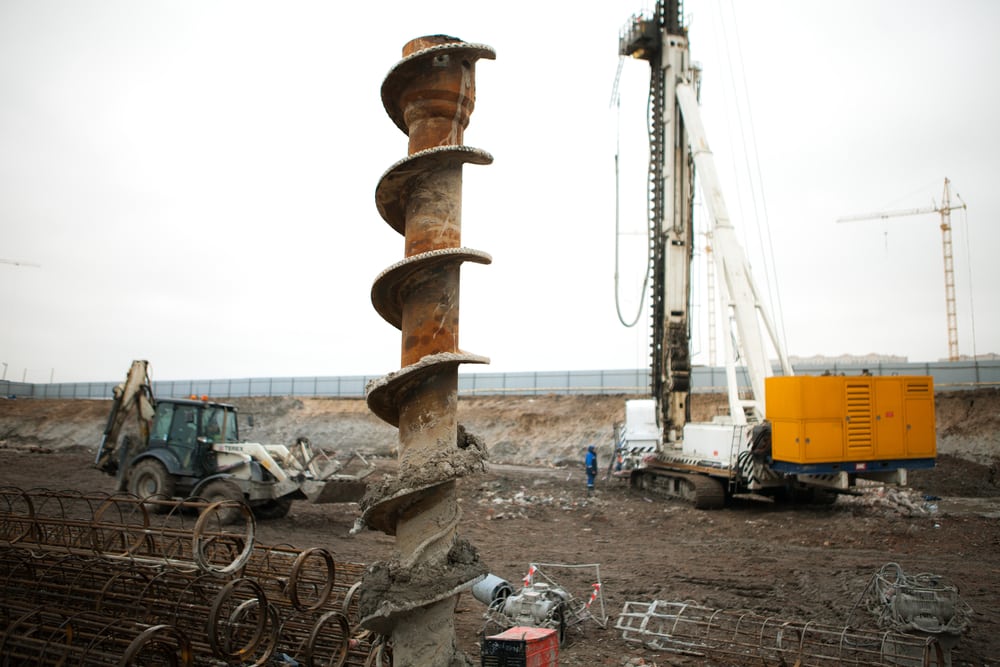
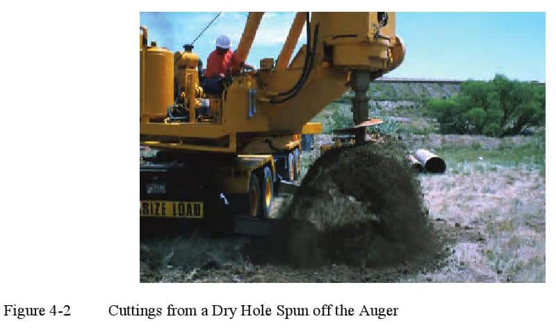
With conditions favorable for a dry excavation, most often a simple rotary auger will be employed, and the operator will remove as much material in one pass as the equipment is capable of handling. The rig is rotated to the side away from the hole and the tool spun to remove the spoil as shown in Figure 4-2. The excavation is carried to its full depth with the spoil from the hole removed from the area by a loader or other equipment. After the excavation has been carried to its full depth, a different tool such as a special clean-out bucket is often used to clean the base of the excavation of loose material. Hand cleaning is possible, but it should not be used unless absolutely necessary and only with the required safety measures (safety casing, air supply, safety harness, radio communication, etc.). More information regarding tools and equipment is provided in Chapter 5.
After the base of the shaft is cleaned, inspected, and approved, the shaft is completed by placing the reinforcement and concrete. The reinforcing cage is typically lowered into position within the hole and then concrete placed through the center of the shaft, flowing through the reinforcement to fill the hole. If a full length cage is used, the bottom of the longitudinal bars may be equipped with spacers or “feet” in order that the cage can be set onto the bottom of the shaft (Figure 4-3). Note that in some cases, the reinforcing cage may be placed only in the upper portion of the drilled shaft, presumably for a case in which bending moments are relatively low and a full length cage is not required. The partial-depth cage would be supported by surface skids as the concrete hardens.
In a dry shaft excavation, concrete may be placed by the “free-fall” method, directing the flow into the center of the shaft to avoid hitting the cage or the sides of the hole and dislodging soil debris. The worker in Figure 4-4 is using the last section of the chute from the delivery truck to direct concrete, as in this case the contractor is able to position the delivery truck near the top of the excavation; in other cases a pump line or buckets may be used to deliver concrete to the shaft. In some cases a centering hopper or a short section of tremie pipe is used to direct the concrete down the center of the shaft. Reinforcement and concrete will be discussed in more detail in Chapters 8 and 9.
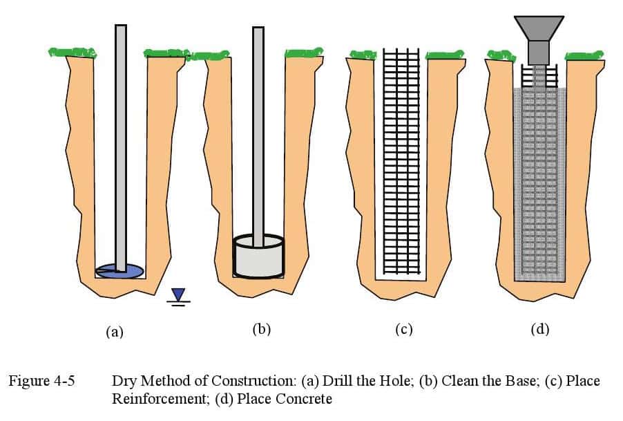
The construction process with a dry hole is illustrated in Figure 4-5:
-
- The shaft is excavated using augers which will likely have teeth to break up the soil.
- The base is cleaned using a bucket or flat bottom tool to remove loose debris and possibly any small amount of water.
- In most typical transportation projects, a full length reinforcing cage is placed.
- The concrete is placed using a drop chute or centering device.
Construction of a shaft using the dry method and open holes should generally be completed in one continuous operation without stopping. Any excavation left open overnight should be cased through soil layers to protect against cave-ins. Dry holes in stable rock formations can be left open overnight without casing. All open holes should be covered for safety.
The length of time necessary to complete the excavation will depend on the soil conditions, the presence of obstructions, and the geometry of the hole. Where homogeneous stiff clays exist, a hole that is 3 ft in diameter can probably be drilled to a depth of 50 ft in less than 1 hour. A longer period of time will be required, of course, if obstructions are encountered or if unforeseen caving occurs that requires conversion to one of the other construction methods. Rock excavation rates can vary widely from less than a foot to as much as 10 or more feet per hour.
4.3 CASING METHOD OF CONSTRUCTION
The casing method is applicable to sites where soil conditions are such that caving or excessive soil or rock deformation can occur when a shaft is excavated. Casing can also be used to extend the shaft excavation through water or permeable strata to reach a dry, stable formation. Unless the bearing formation into which the casing is sealed is stable and dry, it will not be possible to use the casing method alone without the addition of drilling fluid or water.
Installation of casing is generally accomplished in one of three ways.
1. Excavate an oversized hole using the dry method, then place the casing into the hole. This method is suitable only for construction in soils that are generally dry or have slow seepage and that will remain stable for the period of time required to advance the hole to the more stable bearing stratum. The shaft in Figure 4-6 was excavated in East Tennessee through overburden soils to rock in the dry, and then a casing was placed through the soils to rock to prevent caving while the rock socket was drilled.
- Excavate an oversized hole through the shallow permeable strata using a drilling fluid, then place and advance the casing into the bearing stratum. After the casing is sealed into the underlying more stable stratum, the drilling fluid can be removed from inside the casing and the hole advanced to the final tip elevation in the dry. A schematic diagram of this approach is provided in Figure 4-7. Note that since the drilling fluid will have to be flushed out later by the fluid concrete, it must meet all of the requirements for slurry used in the wet method described in Section 4.4.
- Advance the casing through the shallow permeable strata and into the bearing formation ahead of the shaft excavation, and then excavate within the casing in the dry. With this approach, casing may be driven using impact or vibratory hammers or using a casing oscillator or rotator with sufficient torque and downward force to advance the casing through the soil ahead of the excavation. Even larger upward force may be required to pull the casing during concrete placement. A schematic diagram of this approach is provided in Figure 4-8.
Full length temporary casing should always be used if workers are required to enter the excavation, as illustrated in Figure 4-6.
Most casing is made of steel and is recovered as the concrete is being placed. In some circumstances, permanent casing may be used and left in place as a form or as a structural element required in the design of the drilled shaft. Instances requiring the use of permanent casing are discussed in Chapter 6, as are other characteristics of temporary and permanent casings.
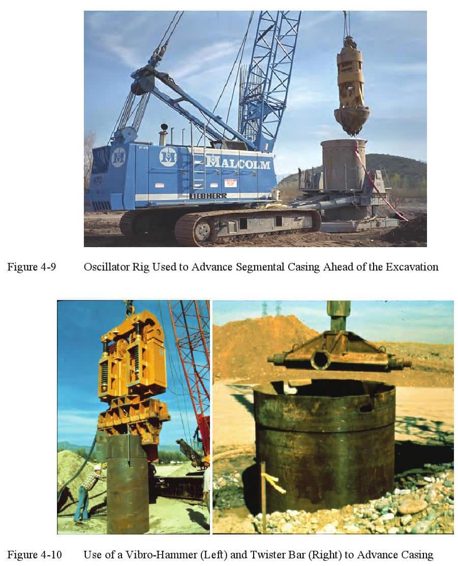
In most cases, the shaft excavation will be advanced below the base of the casing for some distance into the bearing formation of soil or rock, and it is necessary that the casing achieve a seal into this bearing formation in order to control caving or seepage around the bottom of the casing. If the casing is driven with a hammer or oscillator, this machine must have sufficient capability to force the casing into the bearing layer. An oscillator, shown in Figure 4-9, is a hydraulic-powered machine which twists and pushes a segmental-joined casing into the soil. A vibratory hammer is shown on the left of Figure 4-10. The advancement of the casing by the drill rig is normally achieved by attaching a twister bar as shown on the right in Figure 4-10 so that the rig can apply torque and possibly down force onto the casing. Sometimes the casing is equipped with cutting teeth or carbide bits at the bottom to assist in penetration into a hard layer, as shown in Figure 4-11. A more complete description of tools and equipment used to install casing is provided in Chapter 6.
Failure to seal the casing into a watertight formation can result in the inflow of groundwater or sand around the bottom of the casing, resulting in formation of a cavity around the casing. Such a cavity could produce ground subsidence or even collapse at the ground surface. Besides the obvious deleterious effect of ground disturbance and the safety hazard that would be associated with ground movements, this unstable condition can affect adjacent structures. In addition, a large cavity outside the shaft excavation could require a large and unexpected volume of concrete during filling. If a large volume of concrete is lost into a cavity at the time the casing is pulled (step (e) in Figure 4-7 or Figure 4-8), it may be possible that the level of concrete inside the casing could drop so much that the seal of the casing into the concrete could be breached allowing inflow of groundwater or drilling fluid. This breach would result in contamination of the concrete, as illustrated in Figure 4-12. In order to minimize the risk of a large drop in the concrete head within the casing, most contractors would only pull the casing a small amount to break the seal and initiate the flow of concrete behind the casing, and then immediately add more concrete into the casing.
Because of the importance of the permeability of the bearing stratum for construction in the dry within a casing, it is important that this aspect of the soil conditions be evaluated during the site exploration. If the permeability of the bearing stratum is not sufficiently low, seepage could enter the excavation as the slurry is removed. With this condition it may be impossible to remove the groundwater from the excavation, and continued attempts to do so could result in instability of the excavation below the casing. In such a case, the excavation should be completed in the wet as described in the following section. With casing through weaker strata, it may be possible to complete the wet shaft using water as a drilling fluid in lieu of slurry. The casing would still serve to prevent collapse of the soil, and the concrete can be placed underwater with a tremie with simultaneous (or subsequent) extraction of the casing as described in Section 4.4.
 With the casing method, the reinforcing cage will usually need to extend to the full depth of the excavation because it is difficult to keep a partial-length cage in position by a hoist line around which the casing is pulled. Besides the structural requirements, the reinforcing cage must also be designed for the constructability requirements, including stability during pickup and placing of the cage, during the placing of concrete, and during withdrawal of the casing. Out-hook bars should be avoided because of the need to withdraw casing over the cage. Since it is generally necessary to release the cage during withdrawal of the casing, it is necessary that the cage be sufficiently stable that it can stand freely under self-weight in the hole during construction without racking or distorting. Spacers are used to keep the reinforcement cage centered. Because the concrete must flow through the cage to fill the space of and around the casing, there must be sufficient space between bars to permit the free flow of concrete during concrete placement. Additional details relating to reinforcement are provided in Chapter 8.
The concrete used with the casing method must have good flow characteristics in order to flow easily through the reinforcing to fill the space outside the casing and displace any water or slurry around the casing from the bottom up. It is critical that the concrete maintain a hydrostatic pressure greater than that of the fluid external to the casing (trapped slurry or groundwater) as described previously and illustrated in Figure 4-7 and 4-8. The concrete will then flow down around the base of the casing to displace the trapped slurry and fill the annular space. The casing should be pulled slowly in order to keep the forces from the downward-moving concrete on the rebar cage at a tolerable level.
The concrete must also retain it’s workability beyond the duration of the concrete placement operations until the casing is completely removed. If the workability of the concrete (slump) is too low, arching of the concrete will occur and the concrete will move up with the casing, creating a gap into which slurry, groundwater, or soil can enter. The rebar cage may also be pulled up along with the casing and stiff concrete. Even if arching within the casing does not occur, concrete with inadequate workability will not easily flow through the cage to fill the space between reinforcing and the sides of the hole. Downward movement of the cage upon casing withdrawal could indicate that the concrete is pulling the cage laterally toward a void or that the cage is dragged downward into a distorted position due to the downdrag from concrete with inadequate workability. Downward movement of the column of concrete will cause a downward force on the rebar cage; the magnitude of the downward force will depend on the shearing resistance of the fresh concrete and on the area of the elements of the rebar cage. The rebar cage can fail at this point by torsional buckling, by slipping at joints, and possibly by single-bar buckling (Reese and O’Neill, 1995). Additional details relating to concrete are provided in Chapter 9.
The casing method of construction dictates that the diameter of the portion of the drilled shaft below the casing will be slightly smaller than the inside diameter of the casing. In connection with casing diameter, most of the casing that is available is dimensioned by its outside diameter and comes in 6-inch nominal increments of diameter. A contractor would ordinarily use a casing with the increment of outside diameter that is the smallest value in excess of the specified diameter of the borehole below the casing. If casing diameter is specified in other than standard sizes, special pipe may have to be purchased by the contractor, and the cost of the job will be significantly greater.
Casing sometimes needs to be used to stabilize very deep shafts and/or into very strong soil or rock which may make it difficult to remove the casings. In such instances, contractors may choose to “telescope” the casing, as illustrated in the photo of Figure 4-13. With this approach, the upper portion of the shaft is excavated and a large-diameter casing sealed into a suitable stratum. A smaller-diameter shaft will then be excavated below the bottom of the casing and a second casing, of smaller diameter than the first casing, will be sealed into another suitable stratum at the bottom of the second-stage of excavation. The process can be repeated several times to greater and greater depths until the plan tip elevation is reached. With each step, the borehole diameter is reduced, usually by about 6 inches, so that the contractor must plan for the multiple casing approach from the start. This procedure is often used where the soil to be retained contains boulders.
If the top of the interior casing(s) are set below the top of the uppermost casing as shown in Figure 4-13, the contractor must withdraw casing during concrete placement starting with the innermost, being careful to avoid overflowing any casing with concrete and trapping debris below concrete.
-
 SPW911 Sheet Pile Design Software
Rated 5.00 out of 5$150.00 – $599.99
 -
 Sheet Pile Design (PDF Download)
Rated 5.00 out of 5$89.00
 -
 Pile Driving (PDF Download)
$89.00
-
 Marine Construction Volumes 1 & 2 (PDF Download)
$157.00
-
 Pile Driving (Book)
$89.00


